iBeam TE-360 User manual

TE-360 User Manual
iBeamUSA.com
MetraDealer.com
techsupport@metra-autosound.com
� TECH SUPPORT
l ::: J 800-253-8324

1
Directory
1.
Product features
2.
Product accessories description
3.
Product parameters
4.
Precautions before installation
5.
Guide of cables installation
6.
Position and orientation of the cameras installation
adjustment
7.
Placement of the measuring tape and checkerboard
cloth
8.
Placement of the measuring tape and checkerboard
cloth
9.
Introduction of the the main menu and sub-menu
options
10.
Precautions

2
Introduction of 360° Surround-view System
1.Product features
Panoramic View Front View
Right View
Left View
Rear View System Host

3
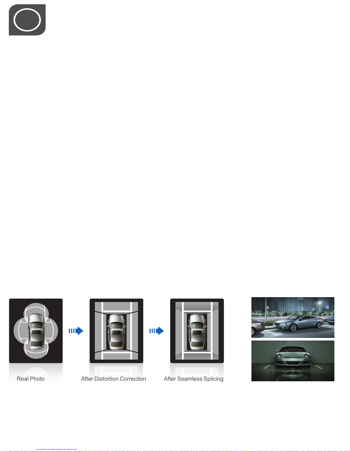
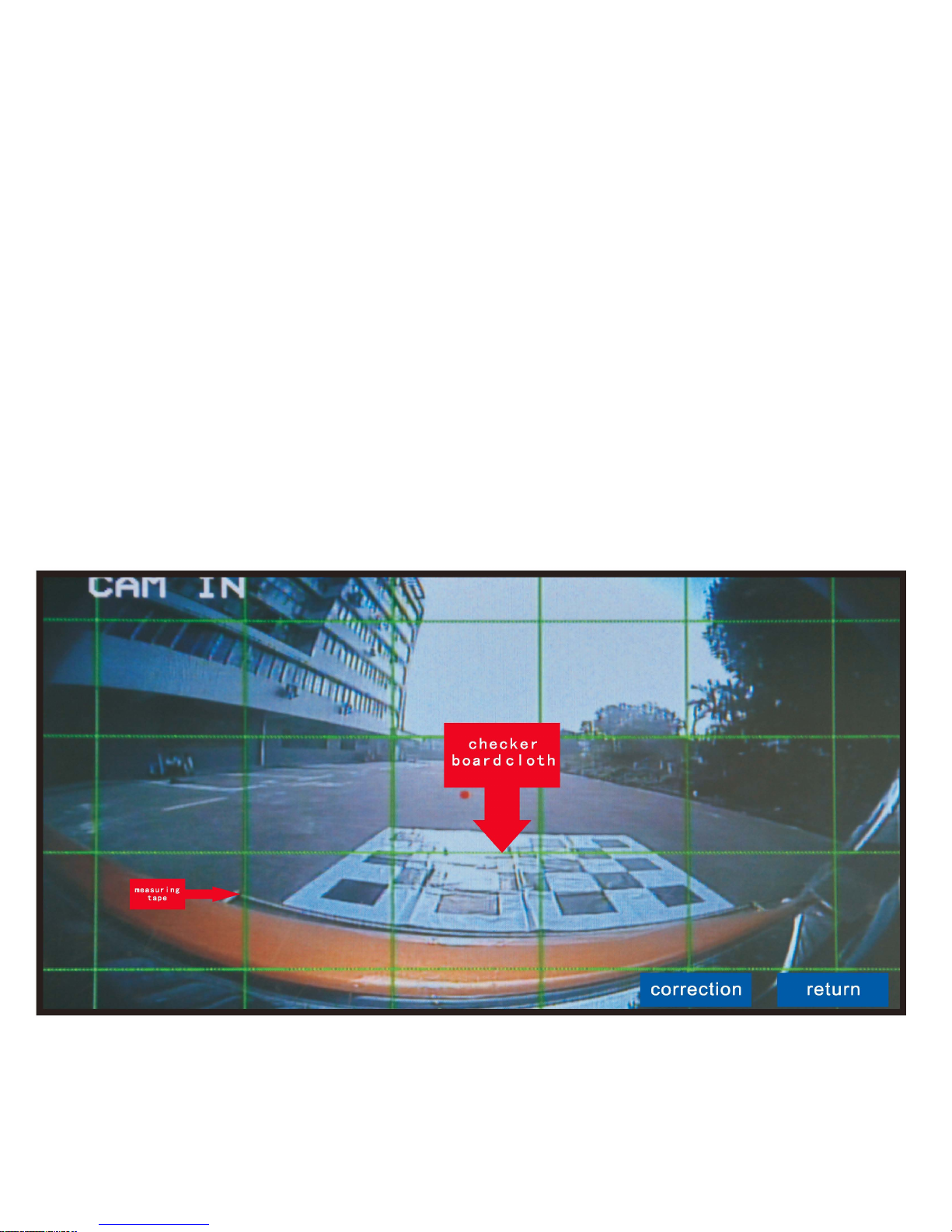
Real Photo After Distortion Correction After Seamless Splicing
Do you find parking frustrating?
Do you find blind spots dangerous?
Do you have enough evidences when road accidents occurs?
?
Without a system that can monitor and record 360 degrees surrounding view of your vehicle, driving will
not be safe and enjoyable.
360 Seamless Surround View Digital Video Recorder is your solution.
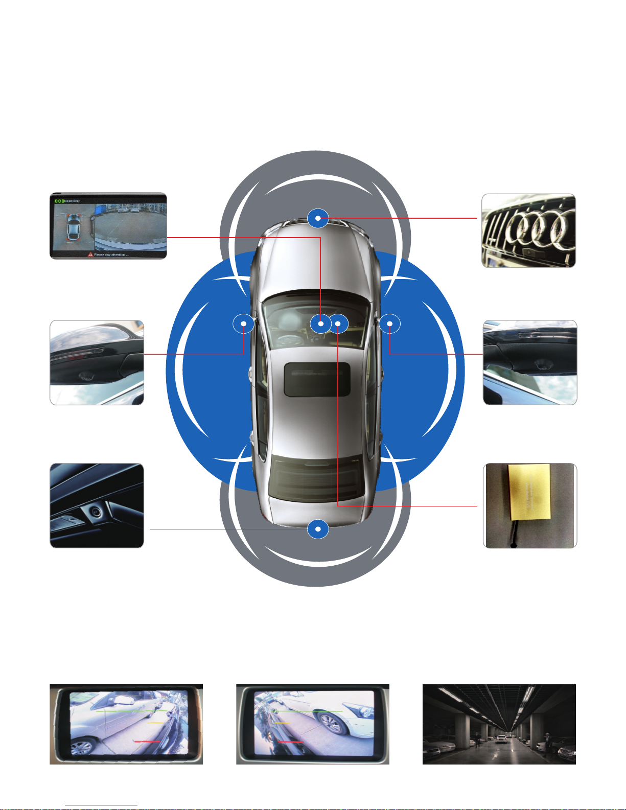
360 Seamless Surround View Digital Video Recorder uses the latest high resolution wide angle Front,
Right, Left and Rear cameras, to first capture surrounding view of your vehicle.
Coupled with the latest software technology, all the camera views are merged to form a single real-time
image seamlessly.
Through an in-car entertainment system or in-car display, you can now monitor and record all driving
activities in real time.
It is a breakthrough technology that protect your interest.
180 degree high resolution wide angle cameras, capture high resolution video both in the day and at night.
While driving, the display will show left or right camera in real time view on display, when either signal is
engaged. While parking, the display will show rear camera in real time view , when in reverse gear.
The display will show front camera in real time view when in drive mode. In all circumstances, rear view will
be the priority.
With each camera, 180 degree Wide Angle Camera, is your extra pairs of eyes, aiding you in parking,
driving at night and eliminating blind spot.
360 Seamless Surround View Digital Video Recorder are your answer to safe driving.
Supporting up to 32GB SD Card, 360 Seamless Surround View Digital Video Recorder can record up to 28
hours of continuous recording.
In normal driving, it automatically records your surrounding view.
When in need, recorded videos can be easily retrieve,play on display or save as evidences.
Round-the-clock monitoring and automatically records when your car is being tampered.
360 Seamless Surround View Digital Video Recorder is the answer for round-the-clock monitoring,
recording and in the event of theft, break-in or accident, 360 Seamless Surround View Digital Video
Recorder Protects you and your car.

4
Parallel parking Reversing
Blind area of turn Low obstacle
The narrow road Front view of abrupt slope
Common Uses

5
n
Name
Main Box
Remote Control
Cameras
Cameras Extend Cable
Remote Control Receiver
Extend Cable
USB Extend Cable(1m)
19.2mm Drill
1.2m Three-core DC Cable
2m AV OUT Cable
Package/User Manual
QTY
1pc
1pc
4pc
4pc
1pc
1pc
1pc
1pc
1pc
1set
Remarks
Left,right,front view each 4m, rear view
6.5m
Connect to USB
Yellow to Battery, Red to ACC, Black to ground
3. Product Parameters as below:
Items
System
Working temperature
Working current
Working voltage
Image resolution
and storage
Main Box Video
Automobile
condition
Equipmet
Parameters
Operation
Language
Interface
Video input
Video output
Video Display
Video standard
cmoamgpe c
re
osmsiporne
i s
Turn Left
Turn Right
Reversing
Data storage
Software upgrade Support SD upgrade
9-36V
440mA
-30~80°C
Performance Indicators
Chinese / English
Graphical Menu Interface (OSD Menu)
4-ch dual video input
Single channel dual video output
Surround view overlooking
PAL, NTSC
H.264 Main profile compression resource
is 4×D1 25frame/sec
Display pictures on the left and surround view/single
left picture/ Non
show pictures on the right and surround view/single
right picture/Non
Simulation surround view display
Support SD card of 32GB, and USB
interface to Hard Disk
Standard Situation
2. . Product accessories description as below
image

6
Yellow to Battery, Red to ACC,
Black to ground.
Remote control receiver, using the 4-core earphone plug,
must be connected tightly, the receiver should be put in a
place easy for receiving remote control.
The plug of video output cable use a standard yellow RCA.
The small red wire connect to reserving signal control wire
of car DVD.
Note: The small red wire cannot connect with reserving
light or any iron ,please cut off the positive wire of the
original reserving light if the automobile (once installed)
has the reserving camera .
5. Guide of cables installation
1). The main box connection diagram (below diagram)
Cable Numbers Cable Pictures Way of connection
①DC extend cable
②Remote
control receiver
cable
③Camera extend
cable
⑤
2 Referring to above install wiring diagram and the following table to do the cables
installation.
USB For recording and software upgrade
2
143
5
7
Video Cable

7
Note: Please pay attention to the definition of the wires when cutting wire connection.
white control wire, red camera power wire (5V), transparent wire for video, Shielding bare
copper wire is for GND.
6.Position and orientation of the cameras installation adjustment
1). Following the below steps to adjust cameras location
Connector Name Functions
Serial port
⑦
The power
indicator light
For function extension
The indicator light will flash for 3-seconds while
power on ,then light up
4). Refer to above diagram, learn the connector function
3) The main box connection diagram (below diagram)
⑥
A,install the front and rear
view cameras according to the
position.
B,when install the left and
right cameras,please check and
see the distance if same from
the front /back wheels to the
lower end of screen according to
AV1/AV2,if not same,please
rotate the left and right
cameras to reach same
distance.(as image 1:A=B)
Note: the location installation and mounting
opening way of the left and right cameras:
Camera mounting drill diameter is 19.2mm, try
to put the hole location on the edge of the
mirror as much as possible (outside), the farther
located, the better quality of seamless joint pictures
will be, the two oblique rings are used to fixed
the cameras always turns downward vertically,
the plastic ring is used to beautification the
opening, opening holes should pay attention to
the both sides be similar, cannot block the lens to
mobilize, refer to the right picture:
oblique
ring
plastic
ring
6
PIC 1
PIC 2
A B

8
7. Placement of the measuring tape and checkerboard
cloth
1 ). Requirement of the tools
4pcs of 7m measuring tape
4pcs of 1.6x 1.2m checkerboard cloth.
2). Placement of the measuring tape and checkerboard cloth
Placement Sequence: firstly, put front and rear first, and than put left and right
Press the power button on the remote controller--choose OK button--choose
set up button--choose surround view and smartjoint--AV3 show the front
camera on display--pull out the measuring tape and you can see the measuring
tape location from the display. Put the 1.6m(the wider sized) check board cloth
close to measuring tape and put in the center of the car.
Placement of the front checkerboard cloth and measuring tape: put
the tape just outside of the bumper. put the cloth close to the tape and
in the center of the car head.

9
Placement of the rear checkerboard cloth and measuring
tape: put the tape just outside of the bumper, put the cloth
close to the tape and in the center of the car.
Placement of the left checkerboard cloth and measuring tape:
put the measuring tape close to the front-back wheel, put the
cloth under the left rear-view mirror.

10
Placement of the right checkerboard cloth and measuring tape: put the
measuring tape close to the front-back wheel, put the cloth under the right
rear-view mirror.
8.Adjustment of surround view
Pic.1
vehicle width
vehicl
e
length
left and
right offset
Note: the left and right checkerboard cloth should be at the same
lever of the measuring tape.
correction return
checker
board cloth
measuring
tape
measuring
tape
Pic.2

11
2). After completed the adjustment of the panorama the cursor will move back to correction of panorama,
ensure that nobody is surrounding the vehicle and then press the OK button, the calibration is complete
(shown as below), and then save →
Note: If a camera fails to detect the appearance of a template, please check the reason in the following
ways:
lens if there is dust and dirt.
3. according to the system reminder, return to recalibrate again.
checker
board cloth
front
measuring tape
Note:
1 Note that the exact binding site of the measuring tapes
2 left and right tapes should be put close to the wheels
3 the checkerboard cloth should put on the binding sites of the integer on
the tape.
start
end
vehicle width
vehicle length 517cm
160cm
left offset
right
offset 160cm
one key for joint
return
200cm

12
9. Introduction of the the main menu and sub-menu options
1)Press the OK button
on the remote control
to select playback
4)Return to the main
menu,select the video
settings,press the OK
button to enter the video
settings
7)Various control settings
options
vehicle width
vehicle length 517cm
left offset 160cm
right offset 160cm
one key for joint
return
200cm
13)Select setting up
and press OK button
to enter
2)Press OK to select search
range
5)video settings
for each function
selection
8)Select surround view smart
joint,and press OK button to
enter the surface of surround
view joint parameter input.
11)Return to main
menu,select maintain button
and press OK button to
enter.
14)Select the left and
right picture adjustment
setting and press OK
button to enter
6)return to the main
menu,select control
settings,press the OK
button to enter control
settings
9)after parameter
input,select one key joint
and press OK button to
enter automotive joint.
12)To see the
various function of
maintain surface
15)Enter the single picture view
of the direction indicator lamp
and use remote control to
compress/remove to adjust

10. Precautions

Notes:
_______________________________________________________________________________
_______________________________________________________________________________
_______________________________________________________________________________
_______________________________________________________________________________
_______________________________________________________________________________
_______________________________________________________________________________
_______________________________________________________________________________
_______________________________________________________________________________
_______________________________________________________________________________
_______________________________________________________________________________
_______________________________________________________________________________
_______________________________________________________________________________
_______________________________________________________________________________
_______________________________________________________________________________
_______________________________________________________________________________
_______________________________________________________________________________
_______________________________________________________________________________
_______________________________________________________________________________
_______________________________________________________________________________

IMPORTANT
If you are having difficulties with the installation
of this product, please call our Tech Support line
at 1-800-253-TECH. Before doing so, look over
the instructions a second time, and make sure
the installation was performed exactly as the
instructions are stated. Please have the vehicle
apart and ready to perform troubleshooting
steps before calling.
When connecting with power cable, please make sure not to mistake the positive and
negative pole, otherwise the fuse will blow immediately for security protection. If it happens,
please replace the blown fuse with a new one with same specification, after connecting
properly to the right pole. Don’t randomly increase the current rating of the fuse, and NEVER
use metal wire as a substitute.
KNOWLEDGE IS POWER
Enhance your installation and fabrication skills by
enrolling in the most recognized and respected
mobile electronics school in our industry.
Log onto www.installerinstitute.com or call
800-354-6782 for more information and take steps
toward a better tomorrow.
Metra recommends MECP
certified technicians
Version 1.0
Table of contents
Other iBeam Car Video System manuals