iBeam TE-WKMN5 User manual

©COPYRIGHT 2020 METRA ELECTRONICS CORPORATION
iBEAMUSA.comiBEAM Vehicle Safety Sytems ®REV. 05/20/2020 INSTTE-WKMN5
Attention!
When testing the aftermarket
equipment, ensure that all factory equip-
ment is connected before cycling the key to
ignition.
TE-WKMN5
INSTALLATION INSTRUCTIONS
#IBEAMSAFETY
Installation............................................................2-3
Wireless Pairing.....................................................4
Display Settings .....................................................5
Wire Lenths ............................................................6
Specifications.........................................................7
TABLE OF CONTENTS
TOOLS REQUIRED
• Wire stripper
• Tape
• Digital Multi-meter
• Cutter
Universal Wireless 5” Monitor
and Camera
Visit iBEAMUSA.com for more detailed informatuon about the product and up-to-date vehicle specific
applications.
Product Features
• Wireless camera and monitor kit
• 5” LCD Monitor
• 20 M / 65 FT range
• DC socket for monitor power with USB for smart device charging
• Video triggered by the camera’s signal
Part Components
A) Monitor B) Camera w/ additional mount C) Accessories
A B C

386-257-1187
|
iBEAMUSA.com
2
Monitor install and wiring
1. Select the desired mounting option
for the monitor. There are two options,
a suction cup mount to mount to the
windshield (Figure A.1) or double stick
tape to be mounted to the dashboard
(Figure A.2). Slide the desired mount
onto the back of the monitor.
2. Clean the surface on which you wish
to mount the monitor and mount the
monitor by either the double sided tape
or suction cup.
3. Plug the DC socket into the monitor and
run the wire in the path shown in Figure
A so safely hide the wire from being
pulled or caught on while operating the
vehicle.
4. Plug the DC socket into the socket in
the vehicle. There is an additional USB
port on the back of the DC socket so
smart device charging can still be done.
(Figure B)
NOTE: If your vehicle DC socket has power
while the vehicle is powered down, you may
need to unplug the monitor while parked so
the battery does not discharge.
Figure A Figure B
2 Amp Charging port
1
2
MONITOR INSTALLATION

REV. 05/20/2020 INSTTE-WKMN5 3
CAMERA INSTALLATION
Camera Installation
1. Mount the camera with either the surface
mount or the license plate mount. If
wanting the surface mount, the two
small screws will need to be removed
to remove the license plate mount and
replace with surface mount.
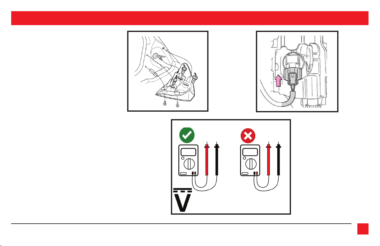
2. Remove the tail light from the vehicle
to allow access to the light bulbs wiring.
(If help is needed, review the vehicles
owners manual section on replacing the
tail light bulbs.) (Figure A)
3. Find the wiring that connects to the
reverse bulb. There is normally 2 wires.
(Figure B) Strip the insulation to expose
the copper wire.
4. Using a Digital Multi-meter on the DC
Voltage setting, to verify the reverse wire.
(Figure C)
5. Connect the wires from the camera
• Connect the RED wire to reverse,
either found at the taillight or
another source for reverse.
• Connect the BLACK wire to chassis
ground. Figure C
Figure B
Figure A
12 V - 12V
Select this symbol on the meter

386-257-1187
|
iBEAMUSA.com
4
Figure A Figure B
WIRELESS PAIRING
Monitor to Camera pairing
1. Before operation, the camera and monitor
need to be paired wireless to each other.
Start by connecting power to both devices. If
camera is connected to reverse, the vehicle
must be put into the reverse gear. NOTE:
Please activate parking brake while pairing
for safety.
2. Once both devices are paired, Press the MENU
button on the monitor and then choose the
PAIRING selection. Then press and hold the
MENU button for 2 seconds to select PAIRING.
3. The monitor will count down 20 seconds to
achieve the pairing of camera to monitor.
Once the pairing has happened, the camera
image will appear. The camera and monitor
are now paired
4. Put the vehicle back into PARK, turn the vehi-
cle off, turn the vehicle back on and shift into
reverse to test the camera and monitor.

REV. 05/20/2020 INSTTE-WKMN5 5
Figure A Figure B
DISPLAY SETTINGS
Display Settings
Brightness
1. Press the MENU button to enter into the
settings menu, use the + and - buttons to
navigate to the PICTURE menu. Press and
hold the MENU button for 2 seconds to enter
the PICTURE menu.
2. Press the + and - buttons to navigate to the
setting you want to choose. Then press and
hold the MENU button for 2 seconds
3. Use the + and - buttons to increase or
decrease the set values.
4. Press the MENU button to exit the settings.
Reversing/flipping the image
1. Press the MENU button to enter into the
settings menu, use the + and - buttons
to navigate to the MIR-FLIP menu. Press
and hold the MENU button to enter the
MIR-FLIP menu.
2. Using the + and - buttons to switch
between NORMAL, MIRROR, FLIP or
MIRROR FLIP.
3. Press the MENU button to exit the
settings.

REV. 05/20/2020 INSTTE-WKMN5 7
TV SYSTEM NTSC
EFFECTIVE PIXEL 976 X 592 pixels
IP RATING IP67
VISUAL ANGLE 120 horizantal 170 diagonal
MIN. ILLUMINATION 0.1 Lux
WORKING VOLTAGE 9 - 16V
WORKING TEMP. -30 C ~ 70 C
STORAGE TEMP. - 40 C ~ 120 C
SCREEN SIZE 5 inch LCD
DISPLAY RESOLUTION 480 X 272
ASPECT RATIO 16:9
POWER CONSUMPTION less than 3 w
SPECIFICATIONS

©COPYRIGHT 2020 METRA ELECTRONICS CORPORATION
iBEAMUSA.comiBEAM Vehicle Safety Sytems ®REV. 05/20/2020 INSTTE-WKMN5
KNOWLEDGE IS POWER
Enhance your installation and fabrication skills by
enrolling in the most recognized and respected
mobile electronics school in our industry.
Log onto www.installerinstitute.com or call
800-354-6782 for more information and take steps
toward a better tomorrow.
®
TE-WKMN5
INSTALLATION INSTRUCTIONS
#IBEAMSAFETY
Having difficulties? We’re here to help.
Contact our Tech Support line at:
386-257-1187
Or via email at:
techsupport@metra-autosound.com
Tech Support Hours (Eastern Standard Time)
Monday - Friday: 9:00 AM - 7:00 PM
Saturday: 10:00 AM - 7:00 PM
Sunday: 10:00 AM - 4:00 PM
Metra Recommends MECP
certified technicians
Table of contents
Other iBeam Car Video System manuals