6
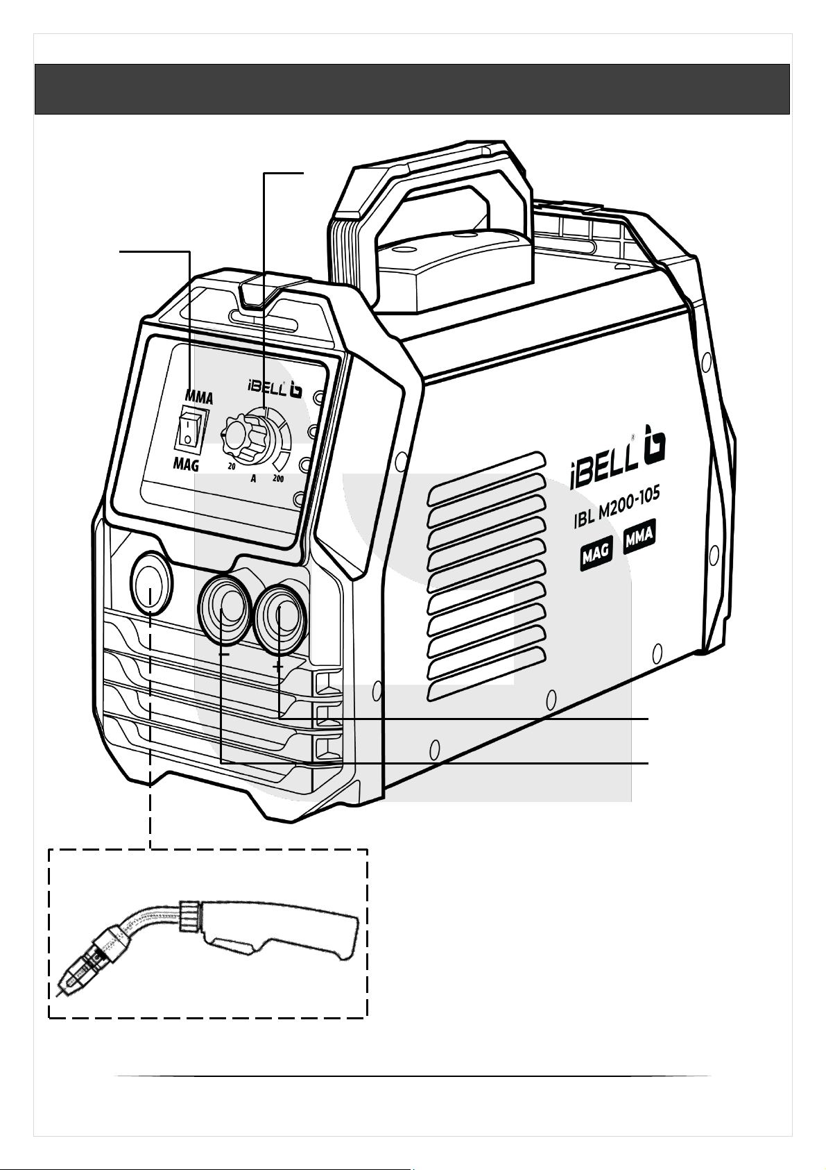
M200-105 Welding machine functions both as Gas-less Flux-cored
MAG (Metal Active Gas) and MMA (Manual Metal Arc) Machine.
▪MAG with Flux cored arc welding uses heat generated by an
electric arc to fuse base metal in the weld joint area. This arc is
struck between the metallic workpiece and the continuously-fed
tubular cored consumable filler wire, with both the wire and the
metallic workpiece melting together to form a weld joint. This
welding works well with most carbon steels, cast iron, stainless
steel and hard facing /surfacing alloys. However, non-ferrous
exotic metals, like aluminium cannot be welded using this
welding technique.
▪In Manual Metal Arc Welding (MMA) with consumable, flux-
covered electrode and a ground clamp, a short-circuit is initially
made on the weld piece. An electric arc forms between electrode
and work-piece, which heats up enough to melt both. As the
electrode melts, the flux coating on the electrode develops gas
and slag, which help protect the weld pool. The gas keeps air and
other pollutants away, while slag forms on top of the weld pool to
protect the weld seam.
▪The machine uses a high performance IGBT Technology, which
is very useful as they give power that can be used for different
welding processes.
Hot Start provides excellent arc ignition without the electrode
sticking and avoiding any metallurgical default in the weld. Its
Anti-sticking feature minimizes the short circuit current in the
event of the electrode sticking to the work piece.
VRD (Voltage Reduction Device) in-built function provides an
additional measure of safety.
Arc force in-built improves the weld performance on the
specified size of electrodes to be used, making the job easier.
▪This machine has a Smart Fan circuitry inside, which work only
when cooling is required, and reduces the amount of dirt which
can be drawn inside thereby reducing power consumption.