iBell Tools IBL T220-105 User manual

TIG / MMA WELDING MACHINES
IBL T220-105 | IBL T250-106
OPERATORS MANUAL

1

2
1. SAFETY PRECAUTIONS _______________________________
2. PRODUCT DESCRIPTION _____________________________
3. PRODUCT OVERVIEW ________________________________
4. PRODUCT SPECIFICATIONS __________________________
5. INSTALLATION ______________________________________
6. GENERAL OPERATION _______________________________
7. TROUBLESHOOTING _________________________________
IBL T220-105 | 250-106
TABLE OF CONTENTS
3
6
7
8
9
12
16

3
These Welding machines functions both as Tungsten Inert Gas
(TIG) welding and MMA (Manual Metal Arc) Machine.
Touching live electrical parts can cause fatal shocks or
severe burns. The electrode and work circuit is
electrically live whenever the output is on. Incorrectly
installed or improperly grounded equipment is a hazard.
▪Insulate yourself from work and ground using dry insulating
mats or covers, big enough to prevent any physical contact with
the work or ground.
▪Do not connect more than one electrode or work cable to any
single weld output terminal.
▪Always verify the supply ground –check and be sure that input
power cord-ground wire is properly connected to ground terminal
in disconnect box or that cord plug is connected to a properly
grounded receptacle outlet.
Welding produces fumes and gases. Breathing these fumes
and gases can be hazardous to your health. Keep your head
out of the fumes. Do not breathe the fumes.
▪Do not weld on coated metals, such as galvanized, lead, or
cadmium plated steel, unless the coating is removed from the
weld area, the area is well ventilated, and if necessary, while
wearing an air-supplied respirator.
SAFETY PRECAUTIONS: MMA & TIG WELDING
WARNING! Read all safety warnings, instructions, illustrations and
specifications provided with this machine. Failure to follow all
instructions listed below may result in electric shock, fire and/or
serious injury. Only qualified persons should install, operate,
maintain, and repair this unit.
ELECTRIC SHOCK
FUMES AND GASES
IBL T220-105 | 250-106

4
Arc rays from the welding process produce intense visible
and invisible (ultraviolet and infrared) rays that can burn
eyes and skin. Sparks fly off from the weld.
▪Wear a welding helmet fitted with a proper shade of filter to
protect your face and eyes when welding or watching.
▪Wear approved safety glasses with side shields under your helmet.
Accidental contact of electrode to metal objects can
cause sparks, explosion, overheating, or fire.
Hot parts can cause severe burns. Do not touch hot parts
bare handed. Allow cooling period before working on gun
or torch.
Overuse can cause overheating; Allow cooling period
and follow rated duty cycle. Reduce the current before
starting to weld again. Do not block or filter airflow.
Moving parts can cause injury. Keep away from moving
parts such as fans. Keep all doors, panels, covers, and
guards closed and securely in place.
High-frequency due to welding can cause interference,
it can interfere with radio navigation, safety services,
sensors computers, and communications equipment.
Electo-static discharge can damage printed circuit
boards. Put on grounded wrist strap before handling
boards or parts.
FURTHER CASES
ARC RAYS
IBL T220-105 | 250-106

5
Cylinders can explode if damaged; Shielding gas
cylinders contain gas under high pressure and damaged
cylinder can explode, so be sure to treat them carefully.
▪Keep cylinders away from any welding or other electrical circuits.
Never hang a welding torch over a gas cylinder.
▪Never allow a welding electrode to touch any cylinder. Never weld
on a pressurized cylinder –explosion will result.
▪When working with cylinders or operating cylinder valves, ensure
that you wear appropriate protectives, boots, clothing, gloves and
safety glasses. When moving cylinders, ensure that the valve is not
accidentally opened in transit.
▪Before operating a cylinder valve: Ensure that the system you are
connecting the cylinder into is suitable for the gas and pressure
involved. Ensure that any accessories (such as hoses attached to
the cylinder valve, or the system being connected to) are securely
connected.
▪Do not, in any manner, come into physical contact with any part
of the welding current circuit, which includes:
i. Workpiece or any conductive material in contact with it.
ii. Ground clamp.
iii. Electrode or welding rod.
iv. Any metal parts on the electrode holder or TIG Torch.
▪All the equipment should be kept in good working condition,
inspected and, when defective, promptly repaired or withdrawn
from service.
▪Training should be sought out in the safe use of this
equipment, the processes and the emergencies.
IBL T220-105 | 250-106
WARNING! The product must be fully assembled before
operation! Do not use a product that is only partly
assembled or assembled with damaged parts! Follow the
assembly instructions step-by-step

6
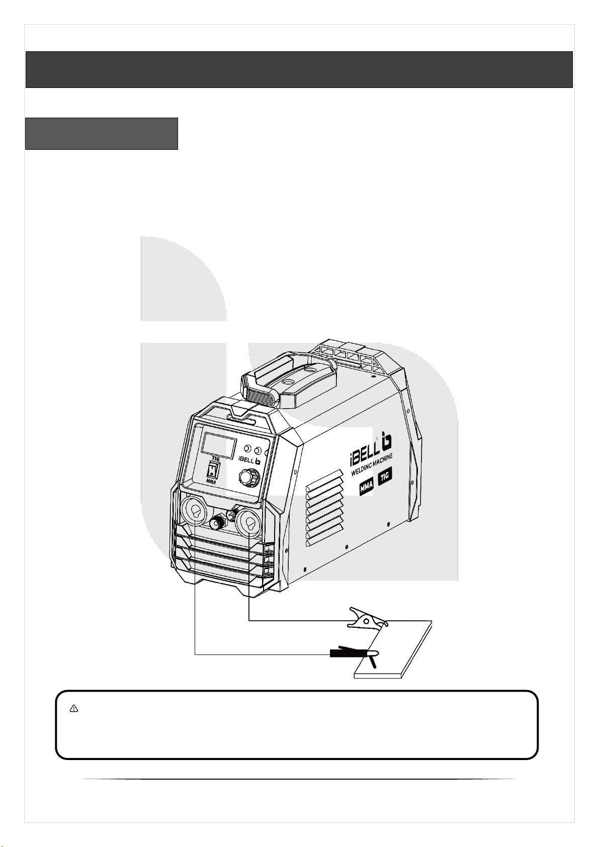
T220-105 and T250-106 Welding machines function both as
Tungsten Inert Gas (TIG) and MMA (Manual Metal Arc) Machine.
▪In Tungsten Inert Gas (TIG) welding, a non-consumable
tungsten electrode is used to produce the weld. The weld area
and electrode are protected by an inert shielding gas (argon)
from oxidation or other atmospheric contamination. A filler
metal is normally used. A constant-current welding power
supply produces electrical energy, which is conducted across the
arc through a column of highly ionized gas and metal vapours.
TIG is most commonly used to weld thin sections of stainless
steel and non-ferrous metals such as aluminium, magnesium,
and copper alloys.
▪In Manual Metal Arc Welding (MMA), with consumable, flux-
covered electrode and a ground clamp, a short-circuit is initially
made on the weld piece. An electric arc forms between electrode
and work-piece, which heats up enough to melt both. As the
electrode melts, the flux coating on the electrode develops gas
and slag, which help protect the weld pool. The gas keeps air and
other pollutants away, while slag forms on top of the weld pool to
protect the weld seam.
▪The machine uses a high performance IGBT Technology, which
is very useful as they give power that can be used for different
welding processes.
Hot Start provides excellent arc ignition without the electrode
sticking and avoiding any metallurgical default in the weld. Its
Anti-sticking feature minimizes the short circuit current in the
event of the electrode sticking to the work piece.
VRD (Voltage Reduction Device) in-built function provides an
additional measure of safety.
Arc force in-built improves the weld performance on the specified
size of electrodes to be used, making the job easier.
PRODUCT DESCRIPTION
IBL T220-105 | 250-106

7
PRODUCT OVERVIEW
1. MMA/ TIG Switch
2. Current Adjustment Knob
3. TIG Torch Switch Socket
4. TIG Gas Electricity Output
IBL T220-105 | 250-106
4
1
2
3
5. ON/OFF Switch
6. Gas Inlet
5. ON/OFF Switch
6. Gas Inlet
Back Panel

8
Model Number
IBL T220-105
IBL T250-106
Input Power (V)
220V±15%
220V±15%
Supply Frequency
(Hz)
50/60Hz
50/60Hz
Input Current (A)
28
43
No Load Voltage (V)
45
45
Output Current (A)
TIG : 5 -160
MMA : 20-140
TIG : 5 -200
MMA : 20-160
Duty cycle(%)
60%
60%
Efficiency (%)
80%
80%
Usable electrodes
(mm)
1 to 4
1 to 5
Hot Start
Built-in
Built-in
Anti-Stick
Built-in
Built-in
ARC Force
Built-in
Built-in
Advanced IGBT
Technology
Yes
Yes
VRD
Built-in
Built-in
Thermal Protection
Yes
Yes
Insulation class
F
F
Protection Class
IP21
IP21
Power factor
0.73
0.73
Arcing way
HF
HF
No-load loss (W)
40
40
PRODUCT SPECIFICATIONS
IBL T220-105 | 250-106

9
▪Connect the welding tongs (grounding clamp and electrode
holder) correctly according to the figure. Firstly, make sure that
cable, welding tongs and quick plugs are connected reliably.
▪Connect the electrode holder in the quick socket with the
polarity of ‘+’, and then tighten it; suitable electrode is connected
to the holder.
▪Connect the grounding clamp into quick socket with the polarity
of ‘-’, tighten it by force; the grounding clamp connects to the
work-piece.
MMA ASSEMBLY
Work piece
WARNING! Make sure that welding cable and earth cable
connections are tight. If a connection is slack, it will result in
voltage drop that will cause the connection to heat.
INSTALLATION
Electrode holder
Earth clamp
IBL T220-105 | 250-106
(*Reverse polarity is acceptable)

10
▪While using TIG welding, Take the TIG Torch and put the Gas-
electricity plug of the welding gun to the Gas Output (4) at the
front panel, and fasten it. Put the Switch connection on the Torch
to the trigger slot (3) and fasten it as well.
▪Place the fastening plug of the torch cable to the ‘-’polarity
socket and Earth clamp at the other terminal, for the work piece.
TIG ASSEMBLY
IBL T220-105 | 250-106
TIG Torch
Earth clamp
Work piece
Flow Meter
Pressure Gauge
Argon
Cylinder
To Gas Inlet
▪Connect the Shielding gas (Argon) cylinder to the gas inlet at
the back panel of the machine.
Back cap
Collet
Collet Body
Nozzle
Tungsten needle
(Electrode)
TIG Torch
Trigger

11
Current setting: The correct current, or amperage setting primarily
depends on the diameter and type of electrode selected. Select an
amperage based on the material thickness and welding position.
MMA :
TIG :
Tungsten needle
(mm)
Current
(A)
Φ1.0
20-80
Φ1.6
50-120
Φ2.0
100-140
Φ2.4
140-200
Thickness (mm)
Current (A)
(CFM)
Gas Flow
(l/min)
Stainless steel
Aluminium
Copper
0.3-0.5
10-40
4
6
6
0.5-1.0
20-40
4
6
6
1.0-2.0
40-70
4-6
8-10
8-10
2.0-3.0
80-130
8-10
10-12
10-12
3.0-4.0
120-170
10-12
10-15
10-15
Diameter of
welding rod (mm)
φ1.6
φ2.0
φ2.5
φ3.2
Welding current
(A)
20-60
60-100
80-120
120-140
PARAMETERS
φ4
140-200
Collet & its body size selection
is based on the needle size.
Nozzle#4 Ø 6 mm
Nozzle#5 Ø 8 mm
Nozzle#6 Ø 10 mm
. . .
Argon gas flow with current adjustment and material thickness
IBL T220-105 | 250-106

12
The MMA/ TIG Switch (1) is used to switch between the two
welding operations: MMA and TIG welding.
▪Always fix earth cable clamp directly on the welding piece.
Turn the power switch to ‘ON’position. Cooling fan inside the
machine should begin to work once welding starts.
▪Clamp the welding rod on the electrode holder, the machine is in
the manual welding mode and in the standby state.
▪In accordance with the thickness of welding work-piece, diameter
of welding rod, working position and technology needs, make
sure suitable welding current with the adjustment knob (2).
(Check out the table on pg.no.11 for electrode size-current criteria)
(If current is too high, intensified splashing occurs and if low, the melted
welding stick becomes fluid and drop transfer would not proceed smoothly)
For beginners, the first difficulty is priming the arc.
For best results proceed as follows:
▪Test the current intensity and the electrode on a piece of scrap
material. Hold the electrode approx. 2 cm above the start of the
joint. Touch the work-piece with the electrode and stroke it
repeatedly on-off the work-piece to start the arc.
▪Watch the arc only through a face shield and keep the arc
length approximately 1–1.5 times the diameter of the electrode.
Hold the electrode at an angle approximately 70° –80°.
▪Wait until the joint has cooled completely before removing the
slag. If you wish to continue welding a joint after taking a break,
the slag at the end of the joint must be removed first. Prime the
arc in the joint and melt the electrode at the point where the two
joints meet.
GENERAL OPERATION
NOTE: It is recommended that you try welding and rate of welding
current first on something else than the actual work piece. You can
start welding after having made the necessary selections.
MMA WELDING
IBL T220-105 | 250-106

13
TIG welding works on same principle of arc welding. In a TIG
welding process, a high intense arc is produced between tungsten
electrode and work piece. A shielding gas (Argon) is also used which
protect the weld surface from oxidization.
▪Open the shielding cylinder and set the required gas flow using
the pressure (flow) adjustment knob on the regulator.
(Check out the table on pg.no.11 for gas adjustments)
▪Press the switch of TIG torch, electromagnetic valve is started.
Sound of HF arc striking can be heard, at the same time argon is
flowing from torch burner.
▪Set suitable welding current and make sure welding current is
adequate to thickness of work piece and process demand.
▪Maintain 2-4mm from tungsten electrode to work piece, press
switch of torch, burn and strike arc, sound of HF arc-striking will
be diminished. The welding machine can be operated now and the
operation can be conducted with the help of a filler rod.
TIG WELDING
NOTE: Before welding user must press switch of torch several seconds
until all of air is be drained out.
▪When welding is over, argon will still flow out in several seconds to
protect welding spot before cooed down. So, the torch must be kept
on welding place some time, before arc has been extinguished.
60-75°
15-30°
Filler Rod
Tungsten Electrode
Shield Gas
IBL T220-105 | 250-106

14
TIG WELDING FUSION TECHNIQUE:
Some welds combining thin materials can be accomplished
without filler metal like edge, corner, and butt joints. This is
known as Fusion welding, where the edges are melted together
using only the heat and arc force. Once the arc is started, the torch
is held in place until a weld pool is created, a circular movement of
the tungsten will assist in creating a weld pool. Once the pool is
established tilt the torch at about a 75° and move smoothly, evenly
along the joint while fusing the materials together.
75°
Weld pool
TIG WELDING WITH FILLER WIRE TECHNIQUE
A filler rod is added to the weld pool to build up reinforcement
and create a strong weld. The filler metal is introduced to the
leading edge of the weld pool formed by fusion. The rod is usually
held at 15°, the arc will melt the filler into the weld pool as the torch
is moved forward.
(Also, a dabbing technique can be used to control the amount of filler wire
added, the wire is fed into the molten pool and retracted in a repeating
sequence as the torch is moved slowly and evenly forward)
It is important during the welding to keep the molten end of the
filler wire inside the gas shield as this protects the end of the wire
from being oxidised and contaminating the weld pool.
Weld pool
75°
15°
Filler Rod
Shield gas
IBL T220-105 | 250-106

15
Store the equipment and accessories out of children’s reach in a
dark and dry place at above freezing temperature. The ideal storage
temperature is between 5°C and 30°C. Store the electric machine in
its original packaging.
All the maintenance work must be conducted under the
condition of complete power failure; please make sure that power
plug is pulled out.
▪Regularly remove the dust on the welding machine with dry
compressed air. When use it in heavy fume and polluted air, do
this job at least once a month. Compressed air should drop down
to the required pressure to prevent damaging the small parts and
units in machine.
▪Avoid water or moist getting into welding machine, or else, blow
the welding machine to dry immediately, then measure the
insulation with insulation resistance meter, it can only be used
when the measuring result is accepted.
▪In the event that the welding machine is not used for long-term, it
should be placed into the original package and stored in dry
place.
▪Any improper or incorrect operation may cause the welder’s
failure and damage. Routine maintenance on power control
switch, grounding device, welding electrode holder, coupling
device and set screws should be performed on a regular basis.
STORAGE
MAINTENANCE
NOTE: Repairing welding equipment should be carried out by a
qualified person using original spare parts. This ensures the safety
of the device as well as yourself.
IBL T220-105 | 250-106

16
The following operations must be performed by qualified technicians.
Before maintenance, please contact with us for professional suggestion.
Problem
Solution
1. Meter doesn’t
display, fan
doesn’t work, no
welding output.
1.1 Make sure power switch is ON.
1.2 Make sure the power source connecting
to input cable is working alright.
2. Meter is normal,
fan is working, no
welding output.
2.1 Check if connector of output terminal is
broken or damaged.
2.2 Check if the control board is damaged
(Connect with our customer service).
3. QC indicator is
ON, fan is
working, meter is
normal.
3.1 IGBT is damaged.
3.2 Rectifier of quick recovery is damaged.
3.3 Control board is broken.
3.4 The feedback circuit is in fault.
4. Too much spatter
4.1 Output terminal polarity connection is
wrong. So please change the polarity
5. Erratic welding
output current or
out of control of
potentiometer.
5.1 The potentiometer is damaged.
5.2 Check that all kinds of connectors are in
poor contact, especially plugs.
6. Power switch
doesn’t work
6.1 Power switch is broken.
6.2 Rectifier bridge is broken, Replace it.
6.3 Check if there is any short circuit of
inner-machine.
TROUBLESHOOTING
MMA WELDING
IBL T220-105 | 250-106

17
Problem
Possible Cause
Solution
1. Unsatisfactory
weld bed, poor
fusion at edges
of weld, Uneven
filler joint.
1.1 Welding current
too high/ low.
1.2 Travel speed
too fast/ low.
1.3 Wrong placement
of filler rod.
1.1 Set the correct
welding current.
1.2 Correct the speed
for weld travel.
1.3 Re-position the
filler rod
2. Arc cannot be
established.
2.1 Work clamp/ torch
not connected or
to wrong terminals.
2.2 Incorrect Gas flow
/ Empty cylinder.
2.1 Connect the
clamp & torch to
its terminals.
2.2 Select the right
flow rate/Change
the cylinders.
3. Electrode melts
/oxidizes when
an arc is struck,
Poor Weld.
3.1 Inadequate gas.
3.2 Gas or Electrode
contaminated.
3.3 Torch is clogged.
3.4 Electrode too small
for welding current.
3.1 Increase flow rate.
3.2 Replace them.
3.3 Clean the torch.
3.4 Increase electrode
size or reduce the
welding current.
4. Arc not smooth,
glitches.
4.1 Wrong tungsten
electrode used.
4.2 Incorrect shielding
gas is being used.
4.1 Select the right
Size. (See pg.no.11)
4.2 Select the right
gas & flow rate.
TIG WELDING
IBL T220-105 | 250-106

18
Do not dispose this product by normal household waste, but take it to a collection
point and recycling of electrical and electronic equipment. This is indicated by the
symbol on the product, user manual or packaging. Re-use, material utilization or
other forms of old appliances, you make an important contribution in protecting our
environment.
Waste electrical products should not be disposed of with
household waste. Please recycle where facilities exist. Check
with your Local Authority or local store for recycling advice.
CONTACT US
HiTech Machineries & Equipments
IV/540E, Thottumugham, P.O, Aluva
Ernakulam(Dist), Kerala, India- 683105
Toll Free : 1800 103 4090
Whatsapp : +91 8943 651651
Website : www.ibelltools.com
Email : icare@ibelltools.com
This manual suits for next models
1
Table of contents
Other iBell Tools Welding System manuals
Popular Welding System manuals by other brands

Cebora
Cebora SOUND MIG 3840/T Pulse Service manual

Red-D-Arc Welderentals
Red-D-Arc Welderentals EXTREME 425 CC Auto-Line owner's manual

Bernard
Bernard Clean Air Gun CA-1.5 Specification sheet

Klutch
Klutch MIG250S owner's manual

kincrome
kincrome KP15002 manual

Hypertherm
Hypertherm Powermax105 Field Service Bulletin

Lincoln Electric
Lincoln Electric CV 510 Operator's manual

EWM
EWM Tetrix 351 AW FW operating instructions

WELDY
WELDY miniwelder geo2 operating manual

Jasic
Jasic Plasma Cut Series Operator's manual

Miller Electric
Miller Electric MILLERMATIC 35 SKP-35 owner's manual

Thermal Arc
Thermal Arc 400MSTW CC operating manual