IBM 4800-741 User manual

SurePOS 700 Series
SurePOS 700-721/741/781, 722/742/782
Hardware Service Guide
SA27-4329-04Updated July 14, 2008


SurePOS 700 Series
SurePOS 700-721/741/781, 722/742/782
Hardware Service Guide
SA27-4329-04Updated July 14, 2008

Note
Before using this information and the product it supports, be sure to read the general information under Appendix B, “Safety
information,” on page 97 and Appendix C, “Notices,” on page 103.
Fourth Edition (October 2007)
This edition applies to SurePOS 700 Models 721/741/781 and 722/742/782.
Current versions of Retail Store Solutions documentation are available on the IBM Retail Store Solutions Web site at
http://www.ibm.com/solutions/retail/store/support. Click Publications.
Aform for reader’s comments is also provided at the back of this publication. If the form has been removed, address
your comments to:
IBM Corporation
Retail Store Solutions Information Development
Department ZBDA
PO Box 12195
Research Triangle Park, North Carolina 27709 USA
When you send information to IBM, you grant IBM anonexclusive right to use or distribute whatever information you
supply in any way it believes appropriate without incurring any obligation to you.
©Copyright International Business Machines Corporation 2003, 2008.
US Government Users Restricted Rights –Use, duplication or disclosure restricted by GSA ADP Schedule Contract
with IBM Corp.
Updated July 14, 2008

Contents
Figures ........................... vii
Tables ............................ix
Preface ............................xi
About this guide .........................xi
Who should use this guide ....................xi
How this guide is organized ...................xi
Related publications ......................xi
Sure POS Models 7x1 and 7x2 important driver information ........ xii
Publications accessibility ..................... xii
Summary of changes ...................... xiii
July 2008 ........................... xiii
October, 2007 ......................... xiii
March, 2007 .......................... xiii
August, 2006 ......................... xiii
March, 2006 .......................... xiii
July, 2005........................... xiii
Providing feedback .......................xv
Chapter 1. Introducing the SurePOS 700 Models ............1
Physical characteristics ......................2
Dimensions .........................2
Controls and indicators .....................2
Connectors..........................4
Cooling ...........................8
Environmental and temperature ..................8
Power ............................9
Power switch operation .....................9
Uninterruptible power supply (optional) ...............10
Power management ......................12
Features and options ......................13
Video function ........................15
Local area network ......................15
Audio and headphones .....................15
PC I/O ...........................16
System memory .......................16
Optional USB DASD ......................16
USB support.........................16
Unique software interface ....................17
I/O devices ..........................17
Cash drawers ........................18
Voltage setting for the 4689 DBCS SurePOS Receipt Journal printer ....19
Powered USB connectors ....................20
System and driver support.....................21
Operating systems ......................21
Drivers ...........................21
BIOS ...........................21
Compatibility..........................22
Hardware ..........................22
Software ..........................22
Updated July 14, 2008
©Copyright IBM Corp. 2003, 2008 iii
||
||

Calling for service ........................23
Chapter 2. Removal and replacement procedures ...........25
Before you begin ........................26
Cables, connectors, and headphones ................26
Connecting your cash drawer to SurePOS Models 721, 741, and 781.....27
Removing the slanted I/O trays ...................28
Removing the covers ......................29
Removing the top plate ......................32
Removing the CD-ROM .....................33
Removing the hard disk drive ...................36
Removing the exhaust fan (Models 742 and 782 only) ..........38
Replacing the insulating rubber seal (Models 722, 742, and 782 only).....39
Removing the spline .......................41
Removing the I/O modules ....................42
Removing the I/O module holders ..................43
Removing the air duct (Models 722, 74x, 78x, and C4x)..........44
Removing the processor fan (Models 742, 782 only) ...........45
Removing the heat sink and processor ................45
Removing the control switch card ..................47
Removing the power supply ....................48
Removing the riser card .....................49
Removing the planar.......................54
Removing the UPS .......................56
Removing the expansion housing ..................58
Removing the UPS battery ....................60
Removing the front USB card ...................61
Removing the memory modules ..................62
Removing the front service housing components (wide models only) .....64
Removing the system and bezel latches ..............64
Removing the pull-out handle ..................66
Removing the cable guide....................66
Removing the cable guide arm assembly ..............67
Chapter 3. Problem determination .................73
Preliminary checklist .......................73
Problem isolation ........................74
Special tools requirements ....................75
Using the RAID application ....................75
Determining ahard drive failure..................75
Replacing and rebuilding ahard drive ...............77
Accessing the RAID setup menu .................77
Chapter 4. Diagnostics and configuration settings ..........79
Service and diagnostics .....................79
Using the BIOS setup program ...................79
Navigation and menus .....................79
Saving settings ........................80
Boot device order .......................80
Restoring CMOS default settings ..................80
Appendix A. Parts catalog ....................83
Assembly 1: Models 721, 741 and 781 ................84
Assembly 2: Models 722, 742, and 782 ................88
Assembly 3: Slanted I/O tray ....................92
Assembly 4: Front service assembly .................94
Updated July 14, 2008
iv SurePOS 700 Series: SurePOS 700-721/741/781, 722/742/782 Hardware Service Guide

Line cord assemblies ......................96
Appendix B. Safety information ..................97
Appendix C. Notices ...................... 103
Electronic emission notices .................... 105
Federal Communications Commission (FCC) statement ........ 105
European Union EMC Directive conformance statement ........ 105
Industry Canada Class AEmission Compliance statement ....... 106
Avis de conformité aux normes d’Industrie Canada .......... 106
Germany ......................... 106
Australia and New Zealand ................... 106
Chinese Class Awarning statement ................ 107
Japanese power line harmonics compliance statement ......... 107
Japanese Voluntary Control Council for Interference (VCCI) statement 107
Korean communications statement ................ 107
Taiwanese Class Awarning statement ............... 108
Taiwan contact information .................... 108
Cable ferrite requirement..................... 108
Electrostatic Discharge (ESD) ................... 108
Product Recycling and disposal .................. 109
Battery return program......................110
For Taiwan: .........................110
For the European Union: .................... 111
For California: ........................ 111
Flat panel displays .......................112
Monitors and workstations ....................112
Trademarks..........................112
Appendix D. Intel software license agreement (final, single user) ....113
Important -read before copying, installing or using ...........113
Copyright license.......................113
Ownership of software and copyrights ...............113
Limited media warranty ....................113
Exclusion of other warranties ..................113
Limitation of liability ......................114
Termination of this agreement ..................114
Applicable laws .......................114
Government restricted rights ..................114
Index ............................115
Part number index.......................119
Updated July 14, 2008
Contents v

Updated July 14, 2008
vi SurePOS 700 Series: SurePOS 700-721/741/781, 722/742/782 Hardware Service Guide

Figures
1. Example of the wide and narrow SurePOS 700 series .................1
2. Front panel controls and indicators.........................3
3. Front panel connectors .............................4
4. Overview of rear panel .............................4
5. Rear view of input/output available on all models ...................5
6. USB-only configuration (models 7x1) ........................6
7. USB-only configuration (models 7x2) ........................6
8. RS-485 and USB configuration ..........................7
9. Location of UPS configuration switches ......................11
10. UPS rear view ................................12
11. Setting the cash drawer using the jumper override ..................18
12. Location of printer jumper on the I/O card......................19
13. Example of the powered USB port ........................20
14. Serial number and machine information ......................23
15. Processor power cable ............................26
16. Removing the slanted I/O tray ..........................28
17. Removing the front bezel ............................29
18. Opening the modesty cover ...........................30
19. Replacing the top cover ............................31
20. Top plate screws ...............................32
21. Opening units with front-service housing ......................33
22. Removing the CD-ROM ............................34
23. Example of serial ATA connector (Model C42 only) ..................35
24. Hard disk drive and brackets ..........................37
25. Master and slave connectors ..........................37
26. Exhaust fan (Models 742, and 782 only) ......................38
27. Location of alignment pen holes .........................39
28. Location of alignment pen holes .........................40
29. Removing the spline .............................41
30. Opened I/O latch ...............................42
31. I/O module holders ..............................43
32. Removing the air duct .............................44
33. Processor fan and levers ............................45
34. Heat sink and processor ............................46
35. Removing the control switch card.........................47
36. Removing the power supply ...........................48
37. Example of Model 742 and 782 processor power cable.................48
38. Removing feature cards ............................49
39. Serial connectors...............................50
40. Removing the I/O card cables ..........................50
41. Power connector ...............................51
42. Dump switch ................................52
43. Riser card latch ...............................53
44. Example of stand-offs .............................54
45. Planar location ...............................55
46. Power supply housing bracket ..........................56
47. Lifting the bracket ..............................56
48. Removing the UPS ..............................57
49. Position of system unit and expansion housing ....................58
50. Prying the expansion housing latch upward .....................59
51. Removing the UPS battery ...........................60
52. Removing the front USB card ..........................61
53. Opening the memory module latches .......................62
Updated July 14, 2008
©Copyright IBM Corp. 2003, 2008 vii

54. Replacing the memory modules .........................63
55. Removing the system latch ...........................64
56. Removing the bezel latch............................65
57. Attaching the pull-out handle ..........................66
58. Removing the cable guide ...........................67
59. Positioning the cable guide arm assembly .....................68
60. Attaching the cable guide arm assembly ......................69
61. Extra cord length during routing .........................70
62. Cable assembly arm with cables securely in place ..................71
63. RAID hard drive failure pop-up..........................75
64. Disk drive failure ...............................76
65. Boot up warning ...............................77
66. Example of the RAID setup menu ........................78
67. Location of CMOS jumper—Model 741 and 781 ...................81
68. Location of CMOS jumper—Model 721.......................81
Updated July 14, 2008
viii SurePOS 700 Series: SurePOS 700-721/741/781, 722/742/782 Hardware Service Guide

Tables
1. Models and descriptions ............................2
2. Rear icons and definitions ............................5
3. Port DC loads ................................9
4. Features and options .............................13
5. Cash drawer jumper settings ..........................18
6. Actions to isolate the cause of aproblem ......................74
7. CMOS jumper and pin location by model ......................81
8. Power cords for all models ...........................96
Updated July 14, 2008
©Copyright IBM Corp. 2003, 2008 ix

Updated July 14, 2008
xSurePOS 700 Series: SurePOS 700-721/741/781, 722/742/782 Hardware Service Guide

Preface
About this guide
This guide describes the removal and replacement procedures for the IBM
SurePOS 700 Models 721/741/781 and 722/742/782, which are commonly referred
to in this guide as the SurePOS 700.
Who should use this guide
This guide is to be used by trained point-of-sale equipment service representatives.
How this guide is organized
This guide is organized as follows:
vChapter 1, “Introducing the SurePOS 700 Models,” on page 1describes the
physical dimensions, features, and options of the product.
vChapter 2, “Removal and replacement procedures,” on page 25 describes the
replacement and removal procedures.
vChapter 3, “Problem determination,” on page 73 describes the problem
determination procedures.
vChapter 4, “Diagnostics and configuration settings,” on page 79 describes the
BIOS setup and other control procedures.
vAppendix A, “Parts catalog,” on page 83 lists part numbers for field-replacable
units (FRUs).
vAppendix C, “Notices,” on page 103 contains trademarks that are referenced in
the guide and other miscellaneous notices.
vAppendix B, “Safety information,” on page 97 contains translations of the safety
notices.
v
Related publications
The following IBM publications are also available from the IBM Retail Store
Solutions Web site at http://www.ibm.com/solutions/retail/store/support.
vSafety Information –Read This First,GA27-4004
vSurePOS 700-721/741/781, 722/742/782 Planning, Installation, and Operation
Guide,GA27-4328
vSurePOS 722/742/782, 723/743/783 Operating System Installation Guide,
GA27-4357
vPoint of Sale Options and I/O Devices Service Guide,GC30-9737
vSureMark 4610 Printers User’s Guide,GA27-4151
vSureMark 4610 Printers Hardware Service Guide,GY27-0355
vPoint of Sale Subsystem Programming Reference and User’s Guide,SC30-3560
vPoint of Sale Subsystem Installation, Keyboards, and Code Pages,GC30-3623
v4820 SurePoint Solution Planning, Installation and Service Guide,GA27-4231
v4820 SurePoint Solution System Reference,SA27-4249
Additional information on the CANPOS keyboard is located in the following
publication:
vSurePOS 500/600 Series Systems: Planning, Installation and Operation Guide,
GA27-4254
Updated July 14, 2008
©Copyright IBM Corp. 2003, 2008 xi
|
|
|
|
|
|
|
|
|
|
|

Sure POS Models 7x1 and 7x2 important driver information
SurePOS Models 7x1 and 7x2 require new POS input/output (I/O) and local area
network (LAN) drivers. Existing drivers for Models 4694 and Models 4800 will not
work properly with these products. This notice applies to all operating systems:
DOS, 4690, Microsoft Windows, and Linux. Additionally, ahard drive image for a
predecessor product will not work properly. Be sure to download the appropriate
drivers from the IBM Retail Web site at http://www.ibm.com/solutions/retail/store/
support.
Publications accessibility
The softcopy version of this guide and other related publications are accessibility
enabled.
Updated July 14, 2008
xii SurePOS 700 Series: SurePOS 700-721/741/781, 722/742/782 Hardware Service Guide

Summary of changes
July 2008
(GA27-4328-04) Added new FRU numbers.
October, 2007
This version (GA27-4328-04) is retitled to specify the SurePOS 700 models to
which this publication applies.
March, 2007
Updated Introduction
Updated notices.
Minor wording updates.
August, 2006
This update provides the RoHS-compliant field replacement part numbers.
March, 2006
This version (SA27-4329-02) contains removal and replacement information and
field-replacement unit numbers for the front-service housing option.
July, 2005
This version (SA27-4329-01) documents the addition of the SurePOS 700 Models
722, 742, and 782 and other model variations.
Updated July 14, 2008
©Copyright IBM Corp. 2003, 2008 xiii
|
|
|
|
|

Updated July 14, 2008
xiv SurePOS 700 Series: SurePOS 700-721/741/781, 722/742/782 Hardware Service Guide

Providing feedback
Your feedback is important in helping IBM provide accurate and high-quality
information.
You can use either of these ways to provide feedback:
vGo to http://www.ibm.com/solutions/retail/store. Click Support,then click
Publications.Click the publication comments within the introductory text.
Provide the requested information and your comments. Be sure to include the
name and form number of the document in the [Publication ID] field.
vPrint and complete the form at the end of this document. Return the form to IBM
by mail or by giving it to an IBM representative.
If applicable, include areference to the specific location of the text (for example, the
page or table number) on which you are commenting.
Between major revisions of this document, there might be minor technical updates.
The latest version of this document is available on the Retail Store Solutions Web
site at www.ibm.com/solutions/retail/store/support/publications/.
Updated July 14, 2008
©Copyright IBM Corp. 2003, 2008 xv

Updated July 14, 2008
xvi SurePOS 700 Series: SurePOS 700-721/741/781, 722/742/782 Hardware Service Guide
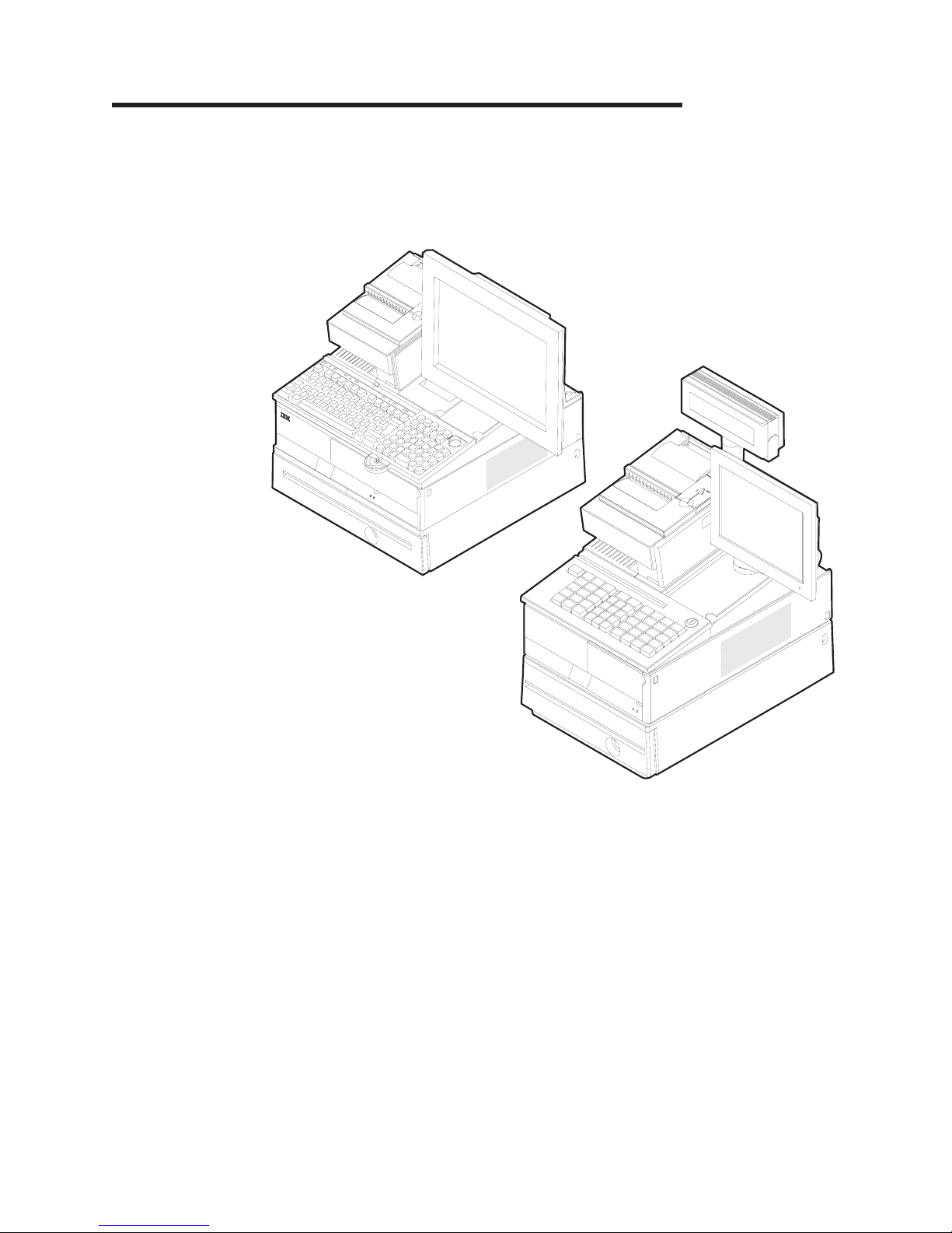
Chapter 1. Introducing the SurePOS 700 Models
The IBM SurePOS 720 are offered in awide footprint and anarrow footprint. Your
packaging options determine the width of the unit. Aunique cover-set feature
provides abroad selection of cover options and colors (see Table 1on page 2).
Figure 1. Example of the wide and narrow SurePOS 700 series
Updated July 14, 2008
©Copyright IBM Corp. 2003, 2008 1

Table 1describes the available models.
Table 1. Models and descriptions
Entry products for cost-sensitve applications:
SurePOS 720 Model
4800:
721 VIA C3 1.2 GHz
722 Intel Celeron 2.0 GHz
Value products that balance cost and high performance:
SurePOS 740 Model
4800:
741 Intel Celeron 2.0 GHz
C41 Intel Celeron 2.0 GHz without installed
POS I/O ports
742 Intel Celeron D326, 2.5 GHz
C42 Intel Celeron D326, 2.5 GHz without
installed POS I/O ports
E42 Intel Celeron D326, 2.5 GHz with
Microsoft Windows Embedded for Point of
Service preloaded
High performance products for intensive POS applications:
SurePOS 780 Model
4800:
781 Intel Pentium 4, 2.4 GHz
W81 Intel Pentium 4, 2.4 GHz with Microsoft
Windows XP Professional preloaded
782 Intel Pentium 4531, 3.0 GHz
For compatibility with your hardware peripherals and software applications, see
“Compatibility” on page 22.
Physical characteristics
This section gives you the physical characteristics for the SurePOS 720 as narrow,
wide, and wide with uninterruptible power supply (UPS) models.
Dimensions
The dimensions for the wide and narrow models are as follows:
Footprint Width Depth Height Weight
Wide 442 mm
(17.4 in.)
475 mm
(18.7 in.)
116 mm
(4.6 in.)
11.8 kg
(26 lbs)
Narrow 320 mm
(12.6 in.)
475 mm
(18.7 in.)
116 mm
(4.6 in)
10.0 kg
(22 lbs)
Wide with UPS 442 mm
(17.4 in.)
475 mm
(18.7 in.)
116 mm
(4.6 in.)
17.7 kg
(39 lbs)
Controls and indicators
Figure 2on page 3describes the front panel controls and indicators.
Updated July 14, 2008
2SurePOS 700 Series: SurePOS 700-721/741/781, 722/742/782 Hardware Service Guide
Other manuals for 4800-741
1
This manual suits for next models
6
Table of contents
Other IBM Cash Register manuals


