IBM Rear Door Heat eXchanger V2 Product manual

Rear Door Heat eXchanger V2
Ty pe 175 6
Installation and Maintenance Guide


Rear Door Heat eXchanger V2
Ty pe 175 6
Installation and Maintenance Guide

Note: Before using this information and the product it supports, read the general information in Appendix B, “Notices,” on page 81,
the Rack Safety Information and Environmental Notices and User Guide documents on the IBM Documentation CD, and the
Important Notices and Warranty Information documents that comes with the product.
Fourth Edition (September 2013)
© Copyright IBM Corporation 2011, 2013.
US Government Users Restricted Rights – Use, duplication or disclosure restricted by GSA ADP Schedule Contract
with IBM Corp.

Contents
Safety ............................v
Chapter 1. Introduction ......................1
The IBM Documentation CD ....................2
Hardware and software requirements ................2
Using the Documentation Browser .................3
Notices and statements in this document................4
Chapter 2. Heat exchanger planning, specifications, and requirements ...5
Planning considerations ......................5
Heat exchanger specifications ....................6
Heat exchanger performance ....................6
Heat exchanger parts and tools ...................9
Secondary cooling loop parts and services...............10
Miscellaneous parts and services supplier ..............10
Coolant distribution unit supplier .................11
Water specifications for the secondary cooling loop ...........12
Control and conditioning of the secondary cooling loop .........12
Installation and support from IBM Integrated Technology Services .....22
Chapter 3. Special instructions if the heat exchanger comes installed on a
rack ............................23
Chapter 4. Installing the heat exchanger ..............29
Installation guidelines ......................29
Installing the heat exchanger....................30
Routing cables through the upper and lower air baffles ..........42
Front-to-rear cable channels and caps ................43
Routing and securing the hoses ..................44
Raised-floor environment ....................44
Raised-floor and non-raised-floor environments ............47
Filling the heat exchanger with water .................48
Chapter 5. Maintaining the heat exchanger .............55
Draining the heat exchanger ....................56
Refilling after a leak in the system ..................60
Leak in the water-supply circuit ..................60
Leak in the heat exchanger ...................60
Maintenance schedule ......................61
Replaceable components .....................61
Replacing the heat exchanger (trained service technician only) .......62
Removing the heat exchanger ..................62
Installing the replacement heat exchanger ..............69
Replacing the latch on the heat exchanger...............76
Appendix A. Getting help and technical assistance ..........77
Before you call .........................77
Using the documentation .....................78
Getting help and information from the World Wide Web ..........78
How to send Dynamic System Analysis data to IBM ...........78
Creating a personalized support web page...............78
Software service and support ...................78
Hardware service and support ...................79
© Copyright IBM Corp. 2011, 2013 iii

IBM Taiwan product service ....................79
Appendix B. Notices ......................81
Trademarks ..........................81
Important notes.........................82
Particulate contamination .....................83
Documentation format ......................83
Telecommunication regulatory statement ...............84
Electronic emission notices ....................84
Federal Communications Commission (FCC) statement .........84
Industry Canada Class A emission compliance statement ........84
Avis de conformité à la réglementation d'Industrie Canada ........84
Australia and New Zealand Class A statement ............84
European Union EMC Directive conformance statement .........85
Germany Class A statement ...................85
VCCI Class A statement ....................86
Korea Communications Commission (KCC) statement .........86
Russia Electromagnetic Interference (EMI) Class A statement.......86
People's Republic of China Class A electronic emission statement .....87
Taiwan Class A compliance statement ...............87
Index ............................89
iv Rear Door Heat eXchanger V2: Installation and Maintenance Guide

Safety
Before installing this product, read the Safety Information.
Antes de instalar este produto, leia as Informações de Segurança.
Læs sikkerhedsforskrifterne, før du installerer dette produkt.
Lees voordat u dit product installeert eerst de veiligheidsvoorschriften.
Ennen kuin asennat tämän tuotteen, lue turvaohjeet kohdasta Safety Information.
Avant d'installer ce produit, lisez les consignes de sécurité.
Vor der Installation dieses Produkts die Sicherheitshinweise lesen.
Prima di installare questo prodotto, leggere le Informazioni sulla Sicurezza.
Les sikkerhetsinformasjonen (Safety Information) før du installerer dette produktet.
Antes de instalar este produto, leia as Informações sobre Segurança.
© Copyright IBM Corp. 2011, 2013 v
Antes de instalar este producto, lea la información de seguridad.
Läs säkerhetsinformationen innan du installerar den här produkten.
Important: Each caution and danger statement in this document is labeled with a
number. This number is used to cross reference an English-language
caution or danger statement with translated versions of the caution or
danger statement in the IBM Rack Safety Information document.
For example, if a caution statement is labeled “Statement 1,”
translations for that caution statement are in the IBM Rack Safety
Information document under “Statement 1.”
Be sure to read all caution and danger statements in this document
before you perform the procedures. Read any additional safety
information that comes with the server or optional device before you
install the device.
Statement 5:
≥18 kg (39.7 lb) ≥32 kg (70.5 lb) ≥55 kg (121.2 lb)
CAUTION:
Use safe practices when lifting.
CAUTION:
or
>32 kg (70.5 lb)
or 32-55 kg (70.5-121.2 lb)
The weight of this part or unit is between 32 and 55 kg (70.5 and 121.2 lb). It
takes three persons to safely lift this part or unit. (C010)
vi Rear Door Heat eXchanger V2: Installation and Maintenance Guide
Statement 6:
CAUTION:
Do not place any object on top of a rack-mounted device unless that
rack-mounted device is intended for use as a shelf.
Statement 7:
CAUTION:
The power control button on the device and the power switch on the power
supply do not turn off the electrical current supplied to the device. The device
also might have more than one power cord. To remove all electrical current
from the device, ensure that all power cords are disconnected from the power
source.
1
2
Statement 8:
DANGER
vPlug power cords from devices in the rack cabinet into electrical outlets
that are located near the rack cabinet and are easily accessible.
vEach rack cabinet might have more than one power cord. Be sure to
disconnect all power cords in the rack cabinet before servicing any
device in the rack cabinet.
vInstall an emergency-power-off switch if more than one power device
(power distribution unit or uninterruptible power supply) is installed in
the same rack cabinet.
vConnect all devices installed in a rack cabinet to power devices installed
in the same rack cabinet. Do not plug a power cord from a device
installed in one rack cabinet into a power device installed in a different
rack cabinet.
Safety vii

Statement 12:
CAUTION:
See the instructions in the rack documentation before you install devices,
remove devices, or relocate the rack.
Statement 14:
CAUTION:
Goggles are needed for the procedure.
(L011)
viii Rear Door Heat eXchanger V2: Installation and Maintenance Guide

Chapter 1. Introduction
This Installation and Maintenance Guide contains instructions for installing, setting
up, and maintaining the IBM®Rear Door Heat eXchanger V2 Type 1756.
Note: Installation of the IBM Rear Door Heat eXchanger V2 Type 1756 is your
responsibility and is not provided as part of the product purchase.
The heat exchanger is a water-cooled door that is mounted on the rear of an IBM
42U 1100 mm Deep Dynamic Rack Type 9363 to cool the air that is heated and
exhausted by devices inside the rack. A supply hose delivers chilled, conditioned
water to the heat exchanger. A return hose delivers warmed water back to the water
pump or chiller. In this document, this is referred to as a secondary cooling loop.
The primary cooling loop supplies the building chilled water to secondary cooling
loops and air conditioning units. The hoses for the secondary cooling loop are not
included with this product. The rack on which you install the heat exchanger can be
on a raised floor or a non-raised floor. Each heat exchanger can remove 100,000
Btu per hour (or approximately 30,000 watts) of heat from your data center.
See “Secondary cooling loop parts and services” on page 10 for information about
hoses, water treatment, and coolant distribution units for supplying conditioned
water.
If you would like to procure IBM installation planning services regarding what is
needed to plan for supplying conditioned water and installing the heat exchanger,
see “Installation and support from IBM Integrated Technology Services” on page 22.
If documentation updates are available, you can download them from the IBM
website. The heat exchanger might have features that are not described in the
documentation that comes with the product, and the documentation might be
updated occasionally to include information about those features, or technical
updates might be available to provide additional information that is not included in
the heat exchanger documentation. To check for updates, go to
http://www.ibm.com/supportportal/.
© Copyright IBM Corp. 2011, 2013 1
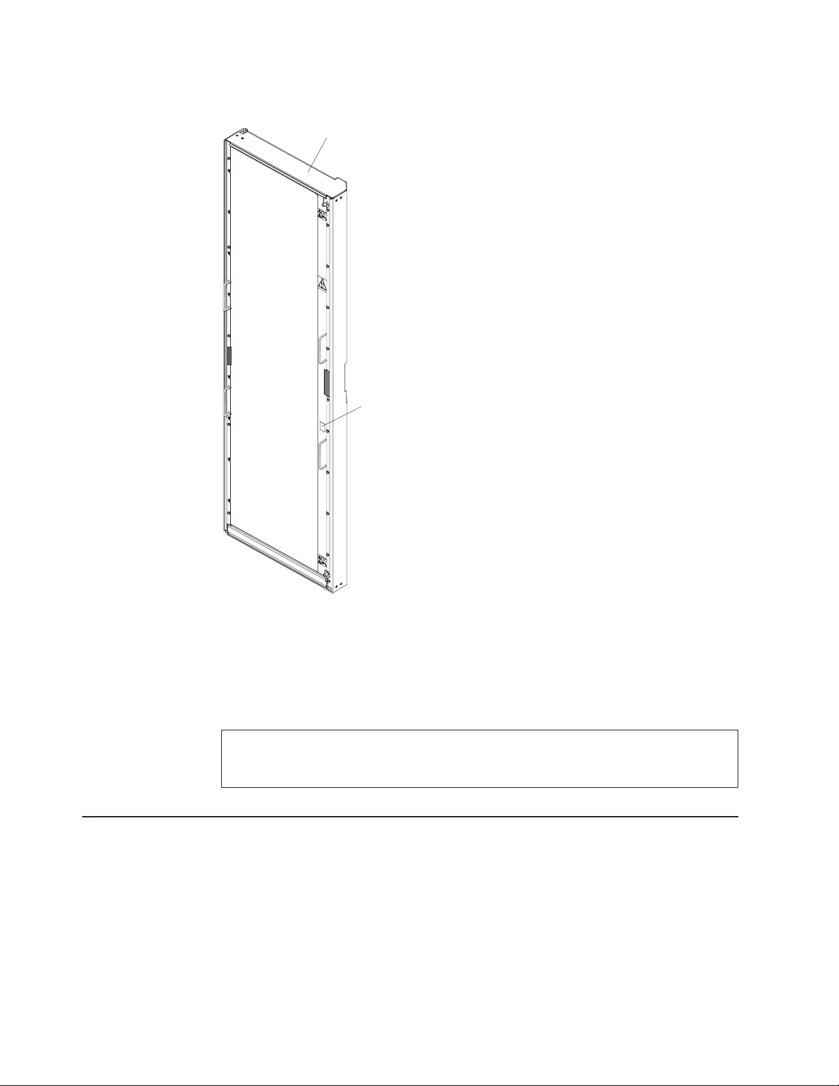
Record information about the IBM Rear Door Heat eXchanger V2 Type 1756 in the
following table. You will need this information if you need to call for service.
The serial number is on the side rail of the heat exchanger, between the two lift
handles.
Product name IBM Rear Door Heat eXchanger V2 Type 1756
Serial number _____________________________________________
The IBM Documentation CD
The IBM Documentation CD contains documentation for your rack product in
Portable Document Format (PDF) and includes the IBM Documentation Browser to
help you find information quickly.
Hardware and software requirements
The IBM Documentation CD requires the following minimum hardware and
software:
vMicrosoft Windows XP, Windows 2000, or Red Hat Linux
Rear door heat
exchanger asembly
Serial
number
Figure 1. Serial number location on the IBM Rear Door Heat eXchanger V2 Type 1756
2Rear Door Heat eXchanger V2: Installation and Maintenance Guide

v100 MHz microprocessor
v32 MB of RAM
vAdobe Acrobat Reader 3.0 (or later) or xpdf, which comes with Linux operating
systems
Using the Documentation Browser
Use the Documentation Browser to browse the contents of the CD, read brief
descriptions of the documents, and view documents, using Adobe Acrobat Reader
or xpdf. The Documentation Browser automatically detects the regional settings in
your computer and displays the documents in the language for that region (if
available). If a document is not available in the language for that region, the
English-language version is displayed.
Use one of the following procedures to start the Documentation Browser:
vIf Autostart is enabled, insert the CD into the CD or DVD drive. The
Documentation Browser starts automatically.
vIf Autostart is disabled or is not enabled for all users, use one of the following
procedures:
– If you are using a Windows operating system, insert the CD into the CD or
DVD drive and click Start --> Run.IntheOpen field, type
e:\win32.bat
where eis the drive letter of the CD or DVD drive, and click OK.
– If you are using Red Hat Linux, insert the CD into the CD or DVD drive; then,
run the following command from the /mnt/cdrom directory:
sh runlinux.sh
Select your rack product from the Product menu. The Available Topics list
displays all the documents for your rack product. Some documents might be in
folders. A plus sign (+) indicates each folder or document that has additional
documents under it. Click the plus sign to display the additional documents.
When you select a document, a description of the document is displayed under
Topic Description. To select more than one document, press and hold the Ctrl key
while you select the documents. Click View Book to view the selected document or
documents in Acrobat Reader or xpdf. If you selected more than one document, all
the selected documents are opened in Acrobat Reader or xpdf.
To search all the documents, type a word or word string in the Search field and
click Search. The documents in which the word or word string appears are listed in
order of the most occurrences. Click a document to view it, and press Crtl+F to use
the Acrobat search function, or press Alt+F to use the xpdf search function within
the document.
Click Help for detailed information about using the Documentation Browser.
Chapter 1. Introduction 3

Notices and statements in this document
The caution and danger statements in this document are also in the multilingual
Rack Safety Information document, which is on the IBM Documentation CD. Each
statement is numbered for reference to the corresponding statement in the Rack
Safety Information document.
The following notices and statements are used in this document:
vNote: These notices provide important tips, guidance, or advice
vImportant: These notices provide information or advice that might help you avoid
inconvenient or problem situations.
vAttention: These notices indicate potential damage to programs, devices, or
data. An attention notice is placed just before the instruction or situation in which
damage might occur.
vCaution: These statements indicate situations that can be potentially hazardous
to you. A caution statement is placed just before the description of a potentially
hazardous procedure step or situation.
vDanger: These statements indicate situations that can be potentially lethal or
extremely hazardous to you. A danger statement is placed just before the
description of a potentially lethal or extremely hazardous procedure step or
situation.
4Rear Door Heat eXchanger V2: Installation and Maintenance Guide

Chapter 2. Heat exchanger planning, specifications, and
requirements
This chapter provides information about planning the installation, and heat
exchanger specifications, parts, tools, and suppliers.
Planning considerations
As you plan the installation of the heat exchanger, include the following
considerations.
vProviding chilled, conditioned water that meets the specifications that are outlined
in “Control and conditioning of the secondary cooling loop” on page 12.
vProcuring and installing the water supply system that is suitable for your data
center. Details are provided in “Water delivery specifications for secondary loops”
on page 14.
vProviding a redundant secondary cooling loop water supply or enough room air
conditioning to handle a tolerable heat load if the function of one or more of the
heat exchangers is compromised. For example, if the rear door is opened for
rack maintenance or conditioned water supply to the door is stopped, the rack
heat load is sent out into the room and must be handled by room air conditioning
until the conditioned water supply is restored.
vProviding floor or ceiling tile cutouts or protective coverings to avoid tripping
hazards on non-raised floors as part of hose management.
CAUTION:
or
>32 kg (70.5 lb)
or 32-55 kg (70.5-121.2 lb)
The weight of this part or unit is between 32 and 55 kg (70.5 and 121.2 lb). It
takes three persons to safely lift this part or unit. (C010)
© Copyright IBM Corp. 2011, 2013 5

Attention:
1. Because of the size and weight of the heat exchanger, three trained persons
are required to install or remove the heat exchanger.
2. You must remove the power from the rack and all components before you
connect or disconnect the water supply lines and drain or fill the heat
exchanger.
Heat exchanger specifications
The following information is a summary of the specifications of the IBM Rear Door
Heat eXchanger V2, Type 1756.
Table 1. Heat exchanger specifications
Door size:
vDepth: 129 mm (5.0 in.)
vHeight: 1950 mm (76.8 in.)
vWidth: 600 mm (23.6 in.)
Door assembly weight:
vEmpty: 39 kg (85 lb)
vFilled: 48 kg (105 lb)
Air movement:
vProvided by servers and other devices in
the rack
Air Temperature drop:
vWith high-heat-load devices, up to 25°C
(45°F) between the air exiting the rack
devices and the air exiting the heat
exchanger
Water:
vSource:
– User-supplied, compliant with
specifications in this document
vPressure:
– Normal operation: <137.93 kPa (20 psi)
– Maximum: 689.66 kPa (100 psi)
vVolume:
– Approximately 9 liters (2.4 gallons)
vTemperature:
– Above dew point
– 18°C ±1°C (64.4°F ±1.8°F) for
ASHRAE Class 1 Environment
– 22°C ±1°C (71.6°F ±1.8°F) for
ASHRAE Class 2 Environment
Note: See “Heat exchanger
performance” for more information.
vRequired water flow rate (as measured
at the supply entrance to the heat
exchanger)
– Minimum: 22.7 liters (6 gallons) per
minute
– Maximum: 56.8 liters (15 gallons) per
minute
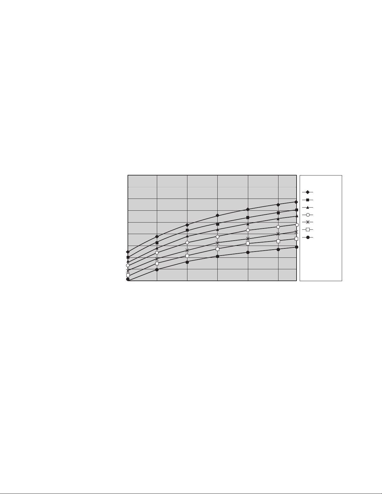
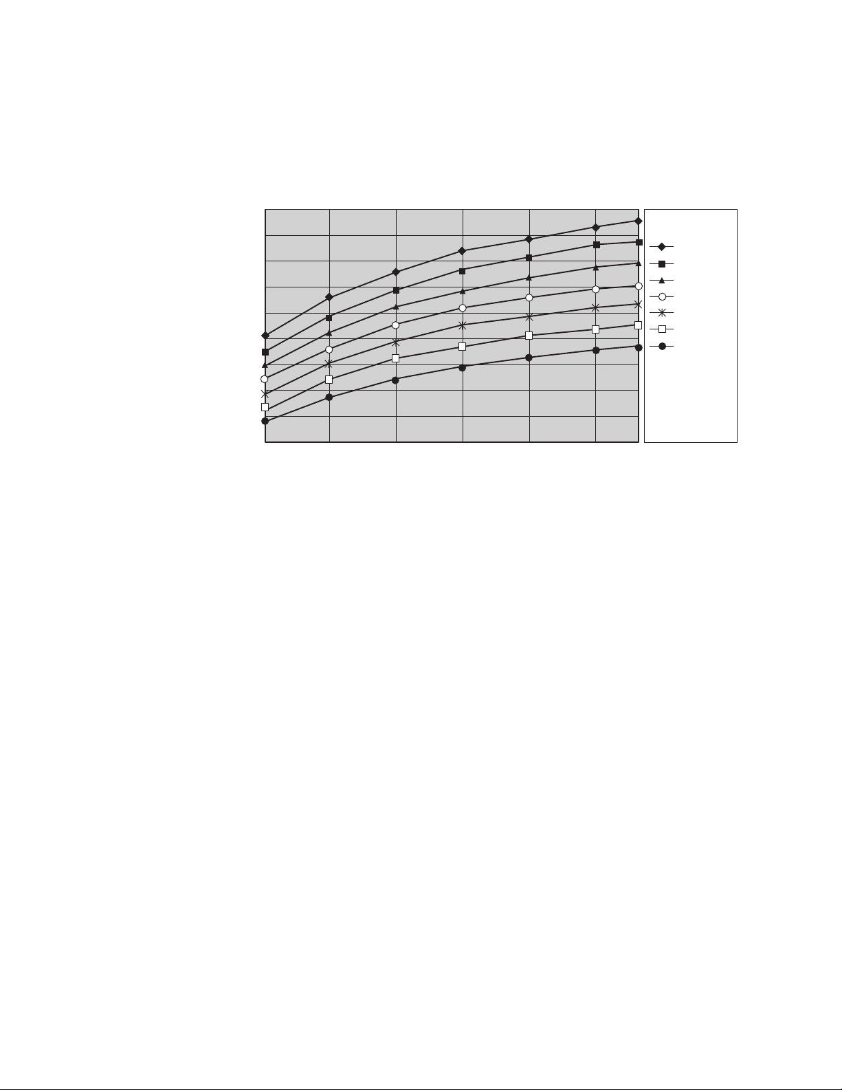
Heat exchanger performance
Expected performance of the heat exchanger is illustrated in Figure 2 on page 7 for
a typical inlet air temperature of 27°C (80.6°F), with a fully populated rack, near
uniform power dissipation, and a 30 kW heat load. By selecting the correct water
inlet temperature and water flow rate, you can achieve the necessary heat removal.
A heat removal of 100% indicates that an amount of heat equivalent to that
generated by the devices has been removed by the heat exchanger and the
average air temperature leaving the heat exchanger is identical to that entering the
rack (27°C [80.6°F] in this example). Heat removal in excess of 100% indicates that
the heat exchanger not only removed all of the heat generated by the devices but
further cooled the air so that the average air temperature leaving the rack is actually
lower than that entering the rack.
6Rear Door Heat eXchanger V2: Installation and Maintenance Guide
Attention: To help maintain optimum performance of the Rear Door Heat
eXchanger and provide proper cooling for all rack components, you must always
take the following precautions:
vInstall filler panels over all unoccupied bays.
vRoute signal cables at the rear of the rack so that they enter or exit the cabinet
through the top and bottom air baffles.
vBundle signal cables together in a rectangle so that the upper and lower
air-baffle sliders are closed as far as possible. Do not bundle signal cables
together in a circular formation. For more information, see “Routing cables
through the upper and lower air baffles” on page 42.
The following illustration shows the typical performance of the heat exchanger, 30
kW heat load.
* As described in “Water-supply requirements for secondary loops” on page 13, a
given water temperature may be used only if the system that is supplying the water
is able to measure the room dew point and automatically adjust the water
temperature accordingly. Otherwise, the water temperature must be above the
maximum dew point that is allowed at that data center installation.
140
130
120
110
100
90
80
70
60
50
% heat removal as function of water temperature and flow rate for
given rack power, rack inlet temperature, and rack air flow rate
4101214
% heat removal
Water flow rate (gpm)
Water
temperature
12°C *
14°C *
16°C *
18°C *
20°C *
68
22°C *
24°C *
Airflow
(cfm) = 2500
Rack Power
(W) = 30000
Tinlet, air
(C) = 27
Figure 2. Typical performance of the heat exchanger, 30 kW heat load
Chapter 2. Heat exchanger planning, specifications, and requirements 7
Performance data is shown in Figure 3 for a 20 kW heat load. Because of the lower
heat load, a specific level of cooling can be achieved with warmer water, a lower
flow rate, or both.
* As described in “Water-supply requirements for secondary loops” on page 13, a
given water temperature may be used only if the system that is supplying the water
is able to measure the room dew point and automatically adjust the water
temperature accordingly. Otherwise, the water temperature must be above the
maximum dew point allowed at that datacenter installation.
140
130
120
110
100
90
80
70
60
50
% heat removal as function of water temperature and flow rate for
given rack power, rack inlet temperature, and rack air flow rate
4101214
% heat removal
Water flow rate (gpm)
Water
temperature
12°C *
14°C *
16°C *
18°C *
20°C *
68
22°C *
24°C *
Airflow
(cfm) = 2000
Rack Power
(W) = 20000
Tinlet, air
(C) = 27
Figure 3. Typical performance of the heat exchanger, 20 kW heat load
8Rear Door Heat eXchanger V2: Installation and Maintenance Guide
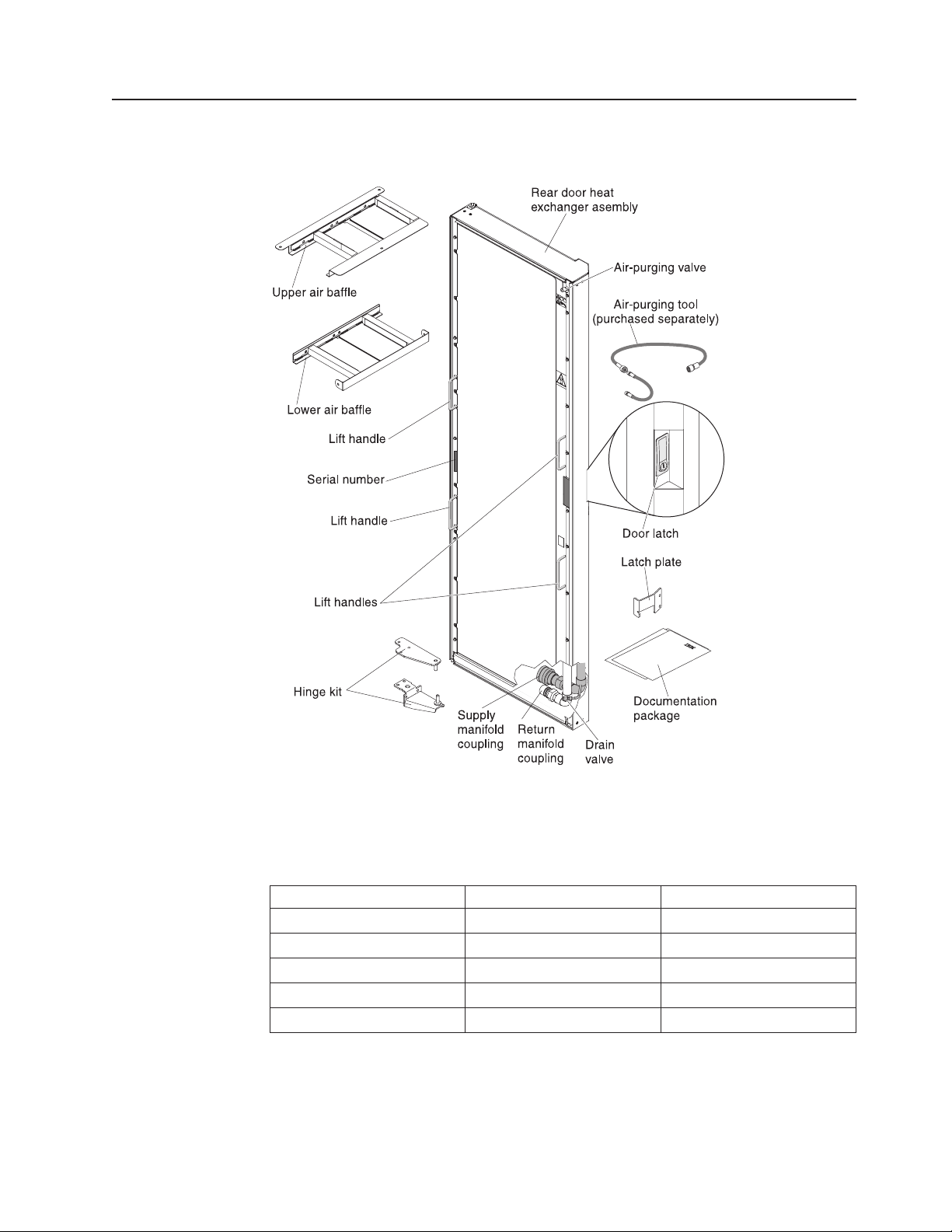
Heat exchanger parts and tools
The following illustration shows the heat exchanger and the parts that come with it.
Use the tools in the following table to install or remove a part or to attach the rear
door heat exchanger.
Table 2. Installation and removal tools
Tool Part to install or remove FRU part number
Phillips screwdriver Hinge bracket; air baffle 73G5363
8 mm socket Air baffle 73G1458
10 mm socket Hinge bracket 73G1463
Ratchet-head wrench Hinge brackets; air baffle 1650840
Platform ladder Hinge bracket (top) 45E0998
Figure 4. The IBM Rear Door Heat eXchanger V2 Type 1756
Chapter 2. Heat exchanger planning, specifications, and requirements 9

Secondary cooling loop parts and services
This section provides lists of suppliers that can provide coolant distribution unit
solutions, flexible hose assemblies, and water treatment that meets the suggested
water quality requirements.
Miscellaneous parts and services supplier
Coolcentric supplies the following secondary loop parts and services to customers
in North America, Europe, Middle East, Africa, and Asia Pacific:
vParts
– Rear door heat exchangers (designed for non-IBM Enterprise racks)
– Coolant distribution units
– 3/4-inch inside diameter hose kits
– Water treatment
– Chillers
– Raised-floor grommets
vServices
– Installation of door and secondary loop items
– Preventive maintenance
You can contact Coolcentric for all or some of the listed items, depending on your
needs.
Coolcentric
a Division of Wakefield-Vette
33 Bridge Street
Pelham, NH 03076
Telephone: 1-603-635-5199
http://www.coolcentric.com
Sales: [email protected]
10 Rear Door Heat eXchanger V2: Installation and Maintenance Guide
This manual suits for next models
1
Table of contents
Other IBM Industrial Equipment manuals


