IC CUBED Chilly Dog Assembly instructions

Chilly DogTM
K-9 SAFETY, VEHICLE CLIMATE CONTROLLER
INSTALLER'S GUIDE w/OPERATING INSTRUCTIONS
Version PLUS 2004.03
By IC CUBED
LIMITED WARRANTY
IC Cubed warrants that all IC Cubed products are free from defects in workmanship
and materials from the factory. IC Cubed will repair or replace any part or parts
that IC Cubed has examined and that IC Cubed is satisfied were originally defective.
Defective parts must be returned to IC Cubed accompanied by a copy of the
corresponding IC Cubed invoice with transportation charges prepaid within one
year of the date of purchase.
This warranty is void if the products or parts have been subject to improper
installation, misuse, accident, negligence, or unauthorized service. This warranty
is void if the unit(s) have been modified or if the unit(s) are used in a fashion
not intended by IC Cubed. This warranty does not cover service or labor charges
that may be incurred during replacement or repair.
IC Cubed will not be responsible for expense, loss, or damage caused indirectly
or directly by the use of IC Cubed products, or any other cause.
No person, dealer or agent is authorized to make modifications or additions
to this warranty or to assume any other liabilities on behalf of IC Cubed.
Removing or defacing serial numbers or other identification, or accessing
internal components will void the warranty stated above.
The rights granted to you by this warranty may be supplemented or restricted
by state law.
IC Cubed reserves all rights to design of logic and hardware
configurations used in all IC Cubed products. All components
used in IC Cubed products are protected by patents held by
or licensed to IC Cubed.
Copyright IC Cubed 2003
Read This Manual Completely
Before Beginning Installation!
TM
For assistance call 877-ICCUBED
SM
Patented Technology

Small 4 Pin
Small 9 Pin
Small 6 Pin
Small 4 Pin
Small 4 Pin
Small 6 Pin
Large 12 Pin
Large 3 Pin
5 ft. extension
Harness
12 ft. extension
Harness
Feature Programming Button
Alert Plug
Connects to
Page or HHT
Dual Remote Temperature
Probe Part# Cp04
Programmable Temperature Display
Part# CTD04
Orange
Start up "Override"
Red
Alert "Override"
Main Control Unit
Part# MCU
1. BLACK, Chassis Ground
2. GREY, Override input Negative hood switch
3. VIOLET, Tachometer input
4. White/Blue, Activation input/Keep alive/ Program selector
5. ORANGE, HI temperature output 200mA Negative
6. BLUE, Factory Alarm Disarm
7. PINK, Switched ignition "KEY" output
8. YELLOW, In park safety input Negative
9. BROWN, Override input Positive Shutdown
10. GREEN, Wait to start input Negative
11. WHITE, Factory Alarm Re-arm
Thin Blue Aux circuit output 200mA Negative
Red 1st Battery Positive Input
Red 2nd Battery Positive Input
Orange Accessory 1 Output 30Amps
Violet Starter Wire
Orange Accessory 2 Output 30Amps
Yellow High Amp 2nd Ignition Output
Pink 1st Ignition Output 30Amps
Red 3rd Battery Positive Input
30A
30A
Tach/Feature
Programming
LED view port
12. WHITE/BLACK, Ready Reset Negative (sensor)

Page 1
The Chilly Dog Kit comes with the following;
Main Control Unit (MCU)
Programmable Temperature Display (CTD) w/mounting hardware
12 ft Extension Cable for CTD
Remote temperature Probe w/12ft of cable(CP04)
Primary Wire Harness (HKC1)
Ignition Switch Relay Harness (HKC2)
Safety Contact Reed Switch (SFT)
Mercury Tilt Hood Switch (HSW)
Start-up/Alert On/Off Switch (CTS) & Harness
Installer's guide w/Operating Instructions
Table of Contents
Page 1: Table of Contents & Ingredients
Page 2: Getting Started, Installing the MCU, Installing the CTD
Page 3: Cp04, Primary harness Black, Grey, Violet
Page 4: Primary harness White/Blue, Orange, Blue, and Pink
Page 5: In park safety connection (Primary harness yellow)
Page 6: Primary harness Brown, Green, White/Black, and White
Page 7: Ignition switch relay harness connections
Page 8: Intentionally Left Blank
Page 9:
Page 10: Feature programming list explained
Page 11:
Page 12: Output Map Table
Programming tach signal, Feature programming mode & list
Programming the temperature thresholds.
Page 13: Operating Instructions, AC setup, CTD description
Page 14: Modes of operation
Page 2
Find an accessible location inside the vehicle cabin to mount the MCU
keeping in mind how you will run the cables for the ignition harness and for
the programmable temperature display (CTD). Planning your installation will
ultimately save time and help to avoid service returns in the future.
If you are not using a remote temp probe (RTP) in your install, you will need
to locate the CTD in an area that is not directly in front of an air conditioner
vent, or that is not exposed to direct sun light as either of these positions will
cause the on board sensor probe to cool off or heat up inaccurately. Typically
you can locate the CTD on the headliner above the rear view mirror. This gives
good coverage and also makes it accessible for the driver for activating and
programming of the system.
CTD04
Rear view mirror
Sun visor
CTD side view
Mounting
Surface
Installing the Main Control Unit (MCU)
This system comes with the hardware necessary to work
properly in a fuel injected gas or diesel powered vehicle.
You can call us toll free at 877-422-8233 (877-IC-CUBED).
Information can also be found at our web site at
www.iccubed.net
Installing the Programmable Temperature Display (CTD04)

Page 3
1. BLACK, Chassis Ground
Wire Connections Explained
2. GREY, Override input Negative hood switch
Connect this wire to a good source of chassis ground. It is preferred to use
a factory ground bolt as opposed to an aftermarket screw.
Connect this wire to the provided mercury switch to prevent accidental
start-up while the vehicle is being serviced. The system will not go into
activation mode while this wire has a ground input. It can also be used
to override the system from a car alarm's negative siren output in case of
forced entry or attempted theft. Use diodes if connected to more than
the hood switch.
<
<
Grey wire
Hood switch negative
Car alarm negative to siren
3. VIOLET, Tachometer input
Connect this wire to a tachometer signal for engine RPMs. The tach feed can
be found at either the negative side of the coil, the back of a tach gauge,
or at the engine computer module. Use a multi-meter to test for the tach wire
as a test light will most likely result in damage to the vehicle. The tach wire will
typically read between 1V and 6V AC.
You must however, take care not to locate the RP03 in front of a vent
or in direct sunlight as this will cause the system to have an inaccurate
temperature reading.
Cp04
Installing the Remote Temperature Probe (Cp04)
Page 4
5. ORANGE, HI temperature output 200mA Negative
This wire will supply a 200mAnegative output while the cabin temperature
is at or above the HI temperature threshold setting.
It can be connected to the trigger wire of the optional horn honk, pager,
window roll-down module, or any negative triggered alerting device.
6. BLUE, Factory Alarm Disarm Pulse
This wire supplies a momentary 200mA negative output at the beginning
of Activation mode.
7. PINK, Key Switched ignition output
This wire supplies a positive ignition output when the vehicle's ignition key is
switched to the run position. It can replace the ignition/accessory input to
a car alarm so the car alarm ignition sense will not trigger and sound the
alarm when the system automatically starts the vehicle. It can also be used
via an RLA to control access to weapons release or trunk pop button.
A pulse negative input at this wire performs multiple functions that are
dependant on the systems corresponding mode:
In Standby or Ready mode a negative pulse will cause the system to enter
activation mode.
In Activation mode a negative pulse will cause the system to exitActivation
mode and return to either Standby or Ready mode depending on the
status of the CTD On/Off switch.
In Feature Programming mode a negative pulse will act as a selector for
the settings of a particular feature. See Feature Programming for details.
The KEEPALIVE function allows the driver to enter the system intoActivation
mode if the vehicle's engine is running via the ignition key. This can be
achieved by applying a negative pulse to this wire, wait 2 seconds,
then switch off the ignition key. NOTE, if either override input has a signal
i.e., break is pressed or hood is open, the Keep Alive function will not work.
Car
Alarm
Momentary Push-button
White/Blue
wire
- Aux output
4. White/Blue, Activation input/Keep alive/ Program selector
Grey Chassis Ground
Mercury Switch

Page 5
8. YELLOW, In park safety input Negative
Connect this wire to a circuit that provides a negative signal when the
vehicle is in park. This can be done by connecting to a factory park
safety circuit or by using the provided SFT contact set. This wire must be
connected for the system to work properly.
Determine if the vehicle is factory equipped with an "in park" output. To work
properly it must supply a 12 volt negative signal with a 500mAheadroom
capacity. This means that in addition to the load of the circuits it is
designed to supply this signal must be capable of supporting an additional
500mA.
NOTE, if you are uncertain about the capacity or functionality of a factory
"in park" circuit DO NOT TIE INTO IT. On many newer vehicles the side effects
will not be realized right away and can cause undesired operation. It is wiser
and easier to user the park safety contact set that is supplied in the kit then
to track down problems later!
Under the driver's side dash, or at the steering column, find the automatic
transmission shift mechanism or strut. Find a mounting location in the park
position in which the safety contact and magnet can be located 1/4in
apart, tip to tip. Remove the cover to expose the adhesive backing on the
magnet & stick in place. Use silicon or epoxy glue to form a permanent
hold and let it set until tacked. Use tie straps to attach the contact to the
shift stabilizing strut. With a multi-meter attached to the white wires of the
contact, you should read a closed circuit when the vehicle is in park. If your
meter does not read a closed circuit, gradually move the contact closer to
the magnet unit you have a closed circuit. Now move the transmission from
the park to the reverse position, the meter should now show an open circuit.
If the circuit is still closed, gradually move the contact away from the magnet
until the circuit show open. If you have made this adjustment test again that
the circuit shows closed when in park. Once properly aligned you can
permanently fix the contact in place with silicone or epoxy glue. Connect
one of the white contact wires to chassis ground.
Factory in park relay
or "starter inhibitor"
Shift stabilizing strut
Shifter mounting bracket
Magnet Contact
Tie straps
Connecting to a Factory Park Safety Circuit
P
R
N
D
Yellow
White wires
Installing the SFT contact set
To Yellow of MCU Page 6
9. BROWN, Override input Positive Shutdown
A positive input at this wire will shutdown the automatic mode of the system.
You can connect this wire to vehicle wire that shows a positive output when
the brake pedal is pressed. The system will not go into activation mode while
this wire has a positive input. It can also be used to override the system from
a car alarm's positive siren output in case of forced entry or attempted theft.
Use diodes to isolate multiple input connections.
<
<
Brown
Brake, switched positive
Car alarm positive to siren
10. GREEN, Wait to start input Negative
For diesel vehicles connect this wire to the negative Wait to Start indicator
input. If the Wait to Start indicator has a positive input then use a relay to
convert polarity.
Black coil -
Red coil +
Yellow relay Com.
Orange relay N.C.
Brown relay N.O.
RLA Chassis ground
Vehicle's Pos Wait to Start signal
Chassis ground
Green wire Pin 10.
11. WHITE/BLACK, Factory Alarm Re-arm Pulse
12. WHITE, Aux circuit output 200mA Negative
This wire supplies a momentary 200mA negative output at the end
of Activation mode.
12. WHITE, Start up Reset Motion Sensor Input
A momentary negative input on this wire will reset (turn on) the
start ready mode of the Chilly Dog. It can be connected to an
interior motion sensor or pressure mat to that detects the
presence of a canine in the vehicle.

Page 7
Red 1st Battery Positive Input
Red 2nd Battery Positive Input
Orange Accessory 1 Output 30Amps
Violet Starter Wire
Orange Accessory 2 Output 30Amps
Yellow
Yellow
Thin Yellow
High Amp Ignition A
High Amp Ignition B
Pink 1st Ignition Output 30Amps
Red
Yellow
3rd Battery Positive Input
4th Battery Positive Input
30A
30A
30A
30A
Ignition Switch
The vehicle’s ignition harness contains many of the wires that are
necessary to start and run the vehicle. This includes power,
starter signal, ignition feed, and accessory feed to the AC blower and
fan. Even though the vehicle may start and run it may be necessary to
energize multiple ignition/accessory feeds for the system to work properly.
On certain Chevy models you must connect a second ignition
wire or you will damage the transmission control module!
Please consult with us if you are unsure any wire connections.
Installing the Ignition Switch Relay Harness
Page 8
Example for a 1998 -2001
Ford Crown Victoria
Ford Vehicle(s)
RLA Ignition Relay
Blue
Chilly Dog Ignition Relay Harness Connection
Red Battery Input
Activation Input

Page 9
8. Activation Pulse. This setting determines how many pulses are need to
trigger the start up process.: DO NOT CHANGE SETTING!
7. Internal Programming Feature: DO NOT CHANGE SETTING!
12. Internal Programming Feature: DO NOT CHANGE SETTING!
13. Internal Programming Feature: DO NOT CHANGE SETTING!
14. Internal Programming Feature: DO NOT CHANGE SETTING!
11. Status output adjustment. DO NOT CHANGE SETTING!
10. Turn the ACC output on or off during wait to start when installed on a
diesel powered vehicle.
9. Changes Pink wire from ignition output to ACC
DO NOT CHANGE SETTING!
5. Starter Crank Time: If step 1 is programmed for voltage sense, you may
need to change the crank time, default 1 sec. If a different crank time is
required momentarily ground the white/blue wire in relation to the desired time,
1 ground pulse = .6 sec., , 3 = 1 sec., 4 = 1.2 sec., 5 = 1.4 sec.,
6 = 1.6 sec., 7 = 1.8 sec., 9 = 2 sec. The LED will blink the corresponding
number of times.
2 = .8 sec.
6. Check Voltage: Some vehicle have a number of accessories that
are energized when the engine is started. For these vehicles the voltage
variation between engine off and running can be very low and the system
may not see the engine as running. For these vehicle program the LO
setting.
3. Run Time: This setting controls the duration that the engine runs per
activation. The default time is 12 minutes and can be change to 24 or
60 minutes. LED will , 2=24min, 3=60min.blink 1=12min
4. This feature selects the characteristics of the Aux 3 output. The default
selection causes the output to flash during Activation mode. Selecting this
off will cause the output to be constant during Activation mode. See wire
hook up for details.
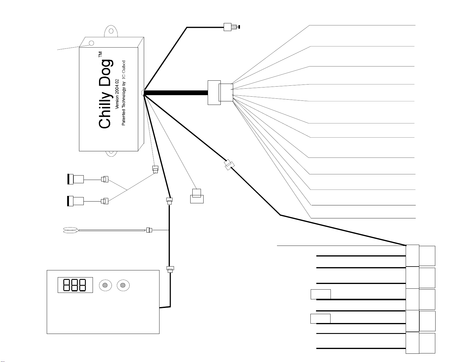
2. Tach wire/Voltage Sense: . If you are using voltage sense then the violet
wire, Pin# 3, does not have to be connected. In voltage sense the unit
will crank the starter for the time set by feature 5. When the starter
has been engaged the system will check voltage to determine if the engine
is running. The voltage level can be programmed to a high or low setting,
see feature 6.
Feature Programming Explained
1. The default selection enable the system to look for either a tach signal
(also default see feature 2) or battery voltage to determine if the vehicle's
engine is running. If this feature is selected off then the system will crank
the starter for the selected time (feature 5) then energize theActivation
circuits for the run time (feature 3) even if the vehicle did not start. It is
recommended to use the default selection.
Page 10
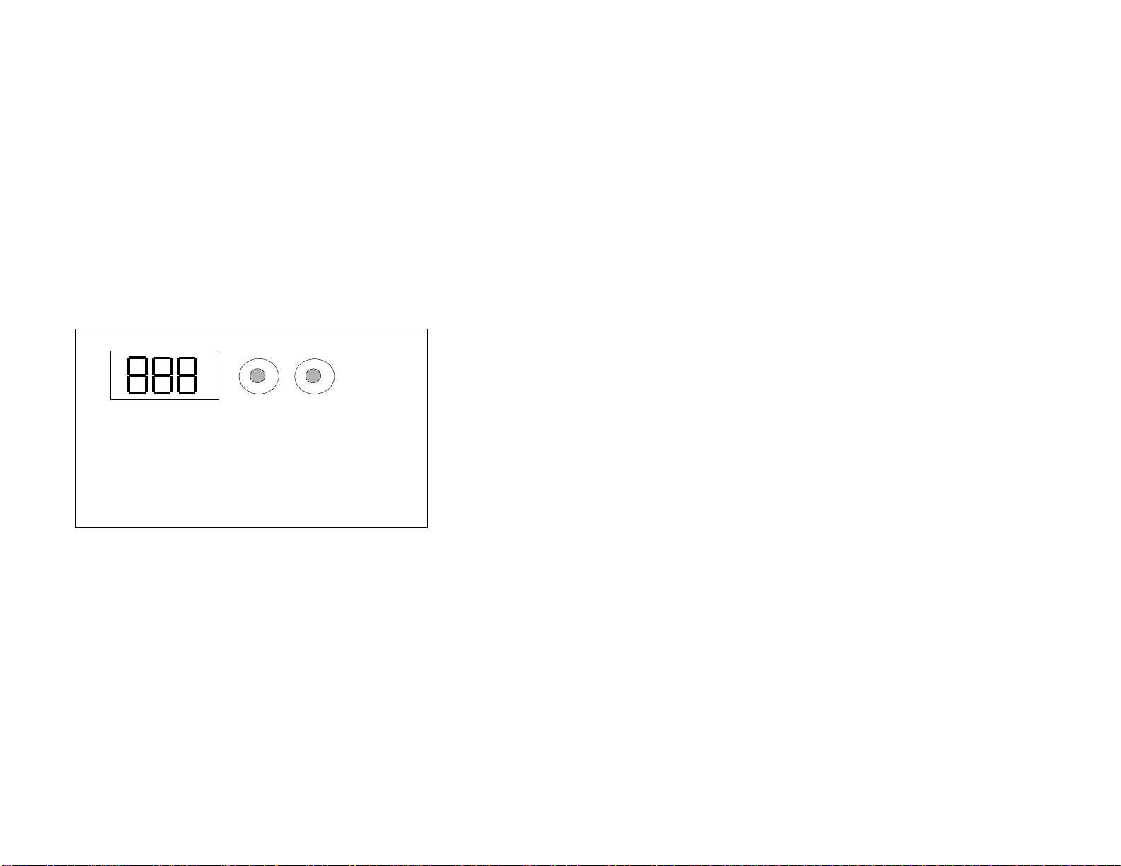
With the key, turn the ignition on and then back off.
Within 10 seconds press and release the Program button the amount
of times corresponding to the feature number.
Press and hold the program button.
The Program LED will blink corresponding to the feature number
Momentarily ground the White/Blue wire "Pin# 4" to toggle the settings.
Release the Program button.
NOTE
The system will exit programming if the ignition is turned on,
the Program button is pressed too many times,
or more than 15 seconds elapses between steps.
To Enter Feature Programming Mode
Programming the Tachometer Signal
After the system is installed, you must program the system to register
the vehicle's tach signal for proper operation. If the installation is on
a tachless diesel vehicle, then you must change feature programming.
Start the vehicle with the ignition key,
within 10 seconds;
Press and hold the program button,
the LED inside the MCU view port will light constant, (see page 7 for location)
release the button and shut off the vehicle.
The tach signal has been learned.
If the LED fails to light, raise the RPMs when programming and
check your tach wire connection.
Most vehicles do not require changes to the default features. More commonly
the vehicle run time may be extended for use in very warm climates to
reduce engine restarts. There is no factory reset for these features, once
change, the option must be reprogrammed if the factory setting is desired.
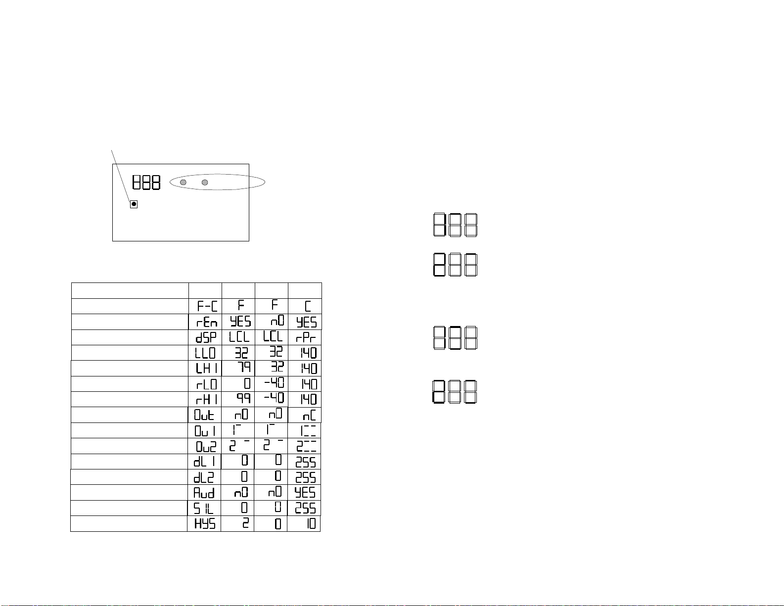
Feature Programming List
Feature Led On Led Off/Flash
1 Engine Check On Engine Check Off
2 Tach Check Voltage Check
3 Run Time 12 Min(2 ) Flash = 24 Min, 3 Flash = 60 Min
4 Not Used
5 Crank Time .6 Sec (1).08 (2), 1. (3), 1.2 (4), 1.4 (5), 1.6 (6)
1.8 (7), 2.0 (8), 4.0 (9)
6 Voltage check high Voltage check low
7 Not Used
8 Activation pulse 1 (1) Do not change!
9 Ignition Output Do not change
10 No Acc during wait start Acc During wait to start
11 Status out (1) Do not change
12 Not Used
13 Not Used
14 Not Used
Default

Page 11 Page 12
Output 1-Local High Start
Output 1-Local High & Low Start
Output 2-Remote High Alert
Output 2-Remote High & Low Alert
The CTD comes pre-programmed to work with the Chilly Dog system.
The settings allow for two high triggers that output to the main control
module. The first is designated to output 1 and is used to activate the
temperature controlled startup, The second is designated to output 2
and is used to activated the High temperature alert. The Chilly Dog
can also be set to start the vehicle or alert based on low temperatures.
See Parameter setting 9 & 10 (Output 1 & Output 2 map designations)
Output 1 = Temperature Controlled Startup
Output 2 = Temperature ActivatedAlert
Default
Expanded (High & Low Temperature Start)
Expanded (High & Low Temperature Alert)
Note:
If using a window drop module in low temperature alert mode, the windows will roll
down when the low temperature is reached.
Table for Output(s) Map Designation Expanded
Programming the Temperature Thresholds
To enter Programming Mode;
Remover the CTD cover.
Press and release the programming button located on the CTD.
Press and release this button to scroll through the 15 parameters.
There are two independent temperature settings that triggerActivation Mode
(Local High Start Output 1),andtrigger Alert Mode (Remote High Alert Output 2).
The factory default settings are Local Start 79, and Remote Alert 99.
There are 15 programmable parameters for the CTD that adjust the following:
Parameter Display Default Min Max
Fahrenheit or Centigrade
Remote Probe Enabled
Display Local or Remote Probe
Set Local Low Limit
Set Local High Limit
Set Remote Low Limit
Set Remote High Limit
Select Output Mode
Map for Output 1-See Table
Map for Output 2-See Table
Set Alarm Delay for Relay 1
Set Alarm Delay for Relay 2
Enable Local Buzzer
Local Buzzer Silence Time
Reset Degrees
Use these buttons to view
and change the Default
Settings.

The Alert feature has three modes of operation;
(1) Alert Ready, (2) Alert, (3) Alert Override.
(1) Alert Ready Mode
The system is normally in Alert Ready Mode. In this mode the system
monitors the vehicle's cabin temperature and reports high temperature
trouble. The factory default setting is 99 degrees Fahrenheit..
(2) Alert Mode
The system is in Alert Mode when the programmed Remote High temperature threshold is
reached or exceeded. A negative signal will be generated at the Orange wire, pin #5, and
can be connected to a number of trouble reporting devices including a horn honk module,
remote pocket pager, and window drop module.
(3) **NEW FEATURE** Alert Override Mode
The system can be switched to Alert Override mode by switching the vehicle ignition key
to the off position then pressing the Alert Override Momentary Switch. The Chilly Dog
temperature start feature will function normally, however, no high alert output will be generated.
The system will automatically return to the Alert Mode the next time the vehicle is started or
if the White wire on pin # 9 of the main harness receives a momentary ground input.
The Temperature Startup feature has four modes of operation;
(1) Override, (2) Standby, (3) Ready, and (4) Activated
WILL NOT
(1) Override Mode
The system is in Override Mode whenever the vehicle is already running via the key, the
vehicle is not in park, the brake pedal is pressed (positive shutdown signal present), or the
vehicle's hood is in the raised position (negative shutdown signal present).
Override Mode supersedes all other modes!
(2), Standby Mode
The system is in Standby Mode when the system ready LED is off. This is located at
the CTD "Programmable Temperature Display". This is controlled by the push-button
switch also located at the CTD. In the Standby mode the system start the
vehicle engine based on the temperature inside the cabin of the vehicle.
In this mode;
The vehicle can be started by a pulse negative input at the White/Blue wire, pin # 4.
This can be supplied by an optional momentary switch or alarm system remote control input.
(3) Ready Mode
The system is in Ready Mode when the system On/Off switch is switched on and the vehicle's
transmission is in park. The ready LED on the On/Off switch will light on. In this mode the
system monitors the vehicle's cabin temperature. When the Local High programmed
temperature is reached, the system goes into Activated Mode (4).
(4) Activation Mode
In Activated Mode the vehicle's engine is started and the circuits necessary to operate
the air conditioning system are powered on. Activated Mode will stay on for 12 minutes
(factory) or program (24 or 60) minutes, then the system will return to the mode it was in
prior to activation. The system can go into Activated Mode by reaching the programmed
temperature as described in (3) or by a negative pulse at the White/Blue wire pin # 4 as
described in (2).
Modes of Operation
Factory Air Conditioner Setup
The vehicle's factory air conditioner must be configured in order for the Chilly Dog
to operate properly.
A manually adjustable controller is the most common type found on
vehicles today. This type requires the operator or user to activate a lever and
or button to select whether or not the AC will be on while the engine is running.
It can also includes a lever or switch that allows the user to adjust the intensity or
output. For this type the AC must be left in the on position and the intensity
should be set to maximum.
An electronically programmable controller requires the user to program the
desired interior temperature into memory. Again the controller must be set
to the on position, and theAC controller should be programmed to a low setting.
Operating Instructions
Page 14
Page 13
Operational Example When Using the optional Horn Honk Module;
Even if the Chilly Dog system has not been turned on by the handler via the
Ready/Standy switch, the Alert feature will trigger when the Remote High
temperature reaches 99 degrees. In this case the handler should first turn
on the Chilly Dog via the ready switch. Once the vehicle starts, the handler
should turn the ignition key to the run position;
(do not step on the brake or turn the ignition key to the crank position);
then press the Alert override button. This will stop the horn from honking. Once the
Chilly Dog has completed one 12 minute run cycle, the Chilly Dog will then shut
down the vehicle and restart if the Local Start temperature is at or above 79 degrees.
The system will automatically return to Alert Mode.
Popular Pet Care Product manuals by other brands

juwel
juwel Trigon 190 instruction manual

PlexiDor
PlexiDor BiteGuard KennelPlex 1418 instruction manual

Canine Innovations
Canine Innovations Pet Convincer Pro user guide

natural PARADISE
natural PARADISE JASMINE XXL manual

Carlson
Carlson 0930PW owner's manual

Omlet
Omlet fido / maya Nook 24 Curtains instruction manual