Icematic DX 40 User manual

DX 40
Service Manual
Cod. 71503041

Table of contents page
Specifications
GENERAL INFORMATION AND INSTALLATION
Introduction
Unpacking and Inspection
Location and levelling
Electrical connections
Water supply and drain connections
Final check list
Installation practice
OPERATING INSTRUCTIONS
Start up
Operational checks
OPERATING PRINCIPLES (How it works)
Freezing cycle
Harvest cycle
Control sequence
Component description
ADJUSTMENT PROCEDURES
Adjustment of the cube size
Wiring diagram
Service diagnosis
MAINTENANCE AND CLEANING INSTRUCTIONS
General
Icemaker
Cleaning instructions of water system
INDICE 1
2
4
4
4
4
5
5
6
7
7
10
12
13
14
17
18-19
20
22
22
22
Page 1

°C
°F
SPECIFICATIONS
ELECTRONIC CUBE DISPENSER
NOTE
.Thedailyice-makingcapacityisdirectlyrelatedtothecondenserairinlettemperature,water
temperature and age of the machine.
To keep your CUBER at peak performance levels, periodic maintenance checks must be carried
out as indicated on page 22 of this manual.
MIN.
10°C
5°C
1 bar
-10%
ice making capacity
40
35
30
25
20
15
10
Kg.
38 32 527 21 15 10
32
38
10
21
40
35
30
25
20
15
10
Kg.
38 32 527 21 15 10
AIR COOLED MODELS
WATER TEMPERATURE
AMBIENT TEMPERATURE
ICE PRODUCED PER 24 HRS.
10
21
32
38
WATER COOLED MODELS
WATER TEMPERATURE
AMBIENT TEMPERATURE
ICE PRODUCED PER 24 HRS.
°C
o
°C
o
°C
o
°C
o
Important operating requirements:
Air temperature
Water temperature
Water pressure
Electr. voltage variations
from voltage rating
specified
on nameplate
MAX.
40°C
40°C
5 bar
+10%
Page 2

Air
Water
Capacity Water req.
the cold store lt/24 HR
SPECIFICATIONS
Basic electr. Amps Watts Nr. of wires Amps fuse
230/50/1 3.2 500 10 3 x 1 m/m210
CUBE DISPENSER
machine specifications
Cubes per harvest: 24 medium
* A 15°C water temperature
Electric power cons.
Kwh per 24 Hr
Cond. unit Finish Comp. HP
Stainless stell 3/8 15 Kg.
Dimensions:
HEIGHT 1720 mm.
WIDTH 380 mm.
DEPTH 510 mm.
WEIGHT 73 Kgs.
_
➝
WATER INLET
WATER INLET - WATER COOLED
WATER OUTLET - WATER COOLED
WATER OUTLET
➝
➝
1690
➝
➝
140
_ _ _ _ _ _ _ _ _ _ _
_
➝
220
➝
793
➝
1720
➝
➀ ➁ ➂ √
➝
➝
➝
210
140*
380*
Page 3

A. INTRODUCTION
This manual provides the specifications and the
step-by-stepproceduresfortheinstallation,start-
up and operation, maintenance and cleaning for
the Cube Dispenser.
The Electronic Cubers are quality designed,
engineered and manufactured.
Their ice making systems are thoroughly tested
providing the utmost in flexibility to fit the needs
of a particular user.
These icemakers have been engineered to our
own rigid safety and performance standards.
NOTE
.Toretainthesafetyandperformance
built into this icemaker, it is important that
installation and maintenance be conducted
in the manner outlined in this manual.
B. UNPACKING AND INSPECTION
1. Call your authorized Distributor or Dealer
for proper installation.
2. Visually inspect the exterior of the packing
and skid. Any severe damage noted should be
reportedtothedeliveringcarrierandaconcealed
damageclaimformfilledinsubjettoinspectionof
the contents with the carrier’s representative
present.
3. a)Cutandremovetheplasticstripsecuring
the carton box to the skid.
b) Remove the packing nails securing the
carton box to the skid.
c)Cutopenthetopofthecartonandremove
the polystyre protection sheet.
d) Pull out the polystyre posts from the
corners and then remove the carton.
4. Remove the rear panel of the unit and
inspectforanyconcealeddamage.Notifycarrier
ofyourclaimfortheconcealeddamageassteted
in step 2 above.
5. Remove top and upper front panel then
remove allinternalsupportpackingandmasking
tape.
6. Check that refrigerant lines do not rub
againstor touchother linesor surfaces,and that
the fan blade moves freely.
7. Check that the compressor fits snugly onto
all its mounting pads.
8. Use clean damp cloth to wipe the surfaces
inside the storage bin and the outside of the
cabinet.
GENERAL INFORMATION AND INSTALLATION
9. See data plate on the rear side of the unit
and check that local main voltage corresponds
with the voltage specified on it.
CAUTION. Incorrect voltage supplied to
the icemaker will void your parts
replacement program.
10. Remove the manufacturer’s registration
card from the inside of the User Manual and fill-
in all parts including: Model and Serial Number
taken from the data plate.
Forward the completed self-addressed
registration card to the Factory.
C. LOCATION AND LEVELLING
WARNING.This IceCuberisdesignedfor
indoorinstallationonly.Extendedperiods
of operation at temperatures exceeding
the following limitations will constitute
misuse under the terms of the Manu-
facturer’s Limited Warranty resulting in
LOSS of warranty coverage.
1. Position the unit in the selected permanent
location.
Criteria for selection of location include:
a)Minimumroomtemperature10°C(50°F)
and maximum room temperature 40°C (100°F).
b) Water inlet temperatures: minimum 5°C
(40°F) and maximum 40°C (100°F).
c) Well ventilated location for air cooled
models.
d) Service access: adequate space must
beleftforallserviceconnectionsthroughtherear
of the ice maker. A minimum clearance of 15 cm
(6")mustbeleftatthesidesoftheunitforrouting
cooling air drawn into and exhausted out of the
compartment to maintain proper condensing
operation of air cooled models.
2. Level the unit in both the left to right and
front to rear directions.
D. ELECTRICAL CONNECTIONS
See data plate for current requirements to
determine wire size to be used for electrical
connections. All icemakers require a solid earth
wire.
Page 4

All ice machines are supplied from the factory
completely pre-wired and require only electrical
power connections to the wire cord provided at
rear of the unit.
Make sure that the ice machine is connected to
its own circuit and individually fused (see data
plate for fuse size).
Themaximumallowablevoltagevariationshould
not exceed -10% and + 10% of the data plate
rating. Low voltage can cause faulty functioning
and may be responsible for serious damage to
the overload switch and motor windings.
NOTE.
All external wiring should conform to
national, state and local standards and
regulations.
Check voltage on the line and the ice maker’s
data plate before connecting the unit.
E. WATER SUPPLY AND DRAIN
CONNECTIONS
GENERAL
Whenchoosingthewatersupplyfortheicecuber
consideration should be given to:
a) Length of run
b) Water clarity and purity
c) Adequate water supply pressure
Sincewateristhemostimportantsingleingredient
in producting ice you cannot emphasize too
much the three items listed above.
Low water pressure, below 1 bar may cause
malfunction of the ice maker unit.
Water containing excessive minerals will tend to
produce cloudy coloured ice cubes, plus scale
build-up on parts of the water system.
WATER SUPPLY
Connect the 3/4" male fitting of the solenoid
waterinletvalve,usingtheflexibletubesupplied,
tothecoldwatersupplylinewithregularplumbing
fitting and a shut-off valve installed in an
accessible position between the water supply
line and the unit.
If water contains a high level of impurities, it is
advisable to consider the use of an appropriate
water filter or conditioner.
WATER DRAIN
The recommended drain tube is a plastic or
flexible tube with 18 mm (3/4") I.D. which runs to
an open trapped and vented drain. When the
drain is a long run, allow 3 cm pitch per meter
(1/4" pitch per foot).
Aventattheunitdrainconnectionisalsorequired
for proper sump drainage.
WATER DRAIN - WATER COOLED MODELS
The recommended drain tube is a plastic or
flexible tube with 18 mm (3/4") I.D. which runs to
an open trapped and vented drain.
NOTE.
Thewatersupplyandthewaterdrain
must be installed to conform with the local
code. In some case a licensed plumber and/
or a plumbing permit is required.
F. FINAL CHECK LIST
1. Is the unit in a room where ambient
temperatures are within a minimum of 10°C
(50°F) even in winter months?
2. Is there at least a 15 cm (6") clearance
around the unit for proper air circulation?
3. Is the unit level? (IMPORTANT)
4. Have all the electrical and plumbing
connectionsbeenmade, andisthewatersupply
shut-off valve open?
5. Has the voltage been tested and checked
against the data plate rating?
6. Has the water supply pressure been
checked to ensure a water pressure of at least
1 bar (14 psi).
7. Checkallrefrigerant linesand conduitlines
to guard against vibrations and possible failure.
8. Havetheboltsholdingthecompressordown
been checked to ensure that the compressor is
snugly fitted onto the mounting pads?
9. Have the bin liner and cabinet been wiped
clean?
10. Has the owner/user been given the User
Manualandbeeninstructedontheimportanceof
periodic maintenance checks?
Page 5

11. Has the Manufacturer’s registration card
been filled in properly? Check for correct model
and serial number against the serial plate and
mail the registration card to the factory.
12. Hastheownerbeengiventhenameandthe
phonenumber ofthe authorizedServiceAgency
serving him?
G. INSTALLATION PRACTICE
1. Hand shut-off valve
2. Water filter
3. Water supply line (flexible hose)
4. 3/4" male fitting
5. Vented drain
6. Open trapped vented drain
7. Drain fitting
8. Main switch
9. Power line
WARNING. This icemaker is not designed for outdoor installation and will not function in
ambient temperatures below 10°C (50°F) or above 40°C (100°F).
This icemaker will malfunction with water temperatures below 5°C (40°F) or above 40°C
(100°F).
Page 6

OPERATING INSTRUCTIONS
Start up
Afterhavingcorrectlyinstalledtheicemakerand
completed the plumbing and electrical
connections, perform the following “Start-up”
procedure.
A. Remove top and upper front panel to be
sure that the tapes securing the curtain and the
spray platen to the evaporator chamber have
been removed.
B. Give power to the unit to start it up by
switching “ON” the power line main disconnect
switch.
The1st GREEN LED will glowtogetherwith the
GREEN LED located in the front of the cube
dispenser.
NOTE.
Every time the unit
returns under power, after
havingbeenswitchedoff,both
the water inlet valve and the
hot gas valve get energized
fora periodof5minutes,thus
to admit new water to the
machine sump reservoir to fill
itupand,eventually,towash-
off any dirt that can have
deposited in it during the unit
off period (Fig.1).
C. During the water filling operation, check to
seethattheincomingwaterdribbles,throughthe
evaporator platen dribbler holes, down into the
sump reservoir to fill it up and also that the
incoming surplus of water flows out through the
overflow pipe into the drain line.
During the water filling phase the components
energized are:
THE WATER INLET SOLENOID VALVE
THE HOT GAS SOLENOID VALVE
THE WATER DRAIN VALVE
NOTE
.If inthe5 minuteslengthofthewater
filling phase the machine sump reservoir
does not get filled with water up to the rim of
the overflow pipe, it is advisable to check:
1.Thewaterpressureofthewatersupplyline
thatmustbeatleast1bar(14psig)Minimum
(Max 5 bar-70 psig).
2.The filtering device installed in the water
line that may reduce the water pressure
below the Minimum value of 1 bar (14 psig).
3. Any clogging situation in the water circuit
like the inlet water strainer and/or the flow
control.
D. At completion of the
water filling phase(5minutes)
theunitswitchesautomatically
intothefreezingcyclewiththe
start up of:
COMPRESSOR
WATER PUMP
FAN MOTOR
(in air cooled version)
and the glowing of the
6th RED LED (Fig.2).
OPERATIONAL CHECKS
E. Install, if necessary, the refrigerant service
gauges on both the high side and low side
service valves to check the compressor head
and suction pressures.
NOTE.
On air cooled models the head
(condensing)pressureiskeptbetween8and
10bar(110and140psig)withicemachineat
21
°
C(70
°
F)ambienttemperature.Theabove
mentioned head pressure values change
accordinglytotheambienttemperature(rising
with the rise of the temperature) and to the
ventilation of the unit.
Inthewatercooledmodels,theheadpressure
iskeptat9bar(125psig)byawaterregulating
valve.
F. Check to see through the curtained ice
discharge opening that the spray system is
correctlyseatedandthatthewaterjetsuniformely
reach the interior of the inverted mold cups; also
make sure that the plastic curtain is hanging
freely and there is not excessive water spilling
through it.
G. Theicemakingprocesstakesplacethereby,
with the water sprayed into the molds that gets
gradually refrigerated by the heat exchange
occuring with the refrigerant flowing into the
evaporator serpentine.
During the freezing process,
whentheevaporator
temperatu-
re falls to reach 0°C (32°F) the
evaporatortemperaturesensor,
located in contact with the
evaporatorserpentine,supplies
alowvoltagepowersignaltothe
electronic control device
(P.C.BOARD) which in first
instance generates the glowing
of the 5th RED LED located in
the front of the printed circuit
board (Fig.3).
FIG. 1
FIG. 2
FIG. 3
Page 7

NOTE.
The length of the defrost cycle (not
adjustable)is automaticallydeterminatedby
themicroprocessorofP.C.BOARDinrelation
of the time T2 necessary for the unit to
reducetheevaporatortemperaturefrom0
°
C
(32
°
F)to-16
°
C(3
°
F)asillustratedinTableB
of PRINCIPLE OF OPERATION.
As shown it is possible to have a different
lengthofthe defrostcyclein connectionwith
the different length of the second phase of
the freezing cycle T2 related to the ambient
temperature situations; shorter when the
ambient temperature is high and longer in
colder ambients so to partially compensate
the length of the freezing cycle, which is
longer in high ambient temperatures and
shorter in low ones.
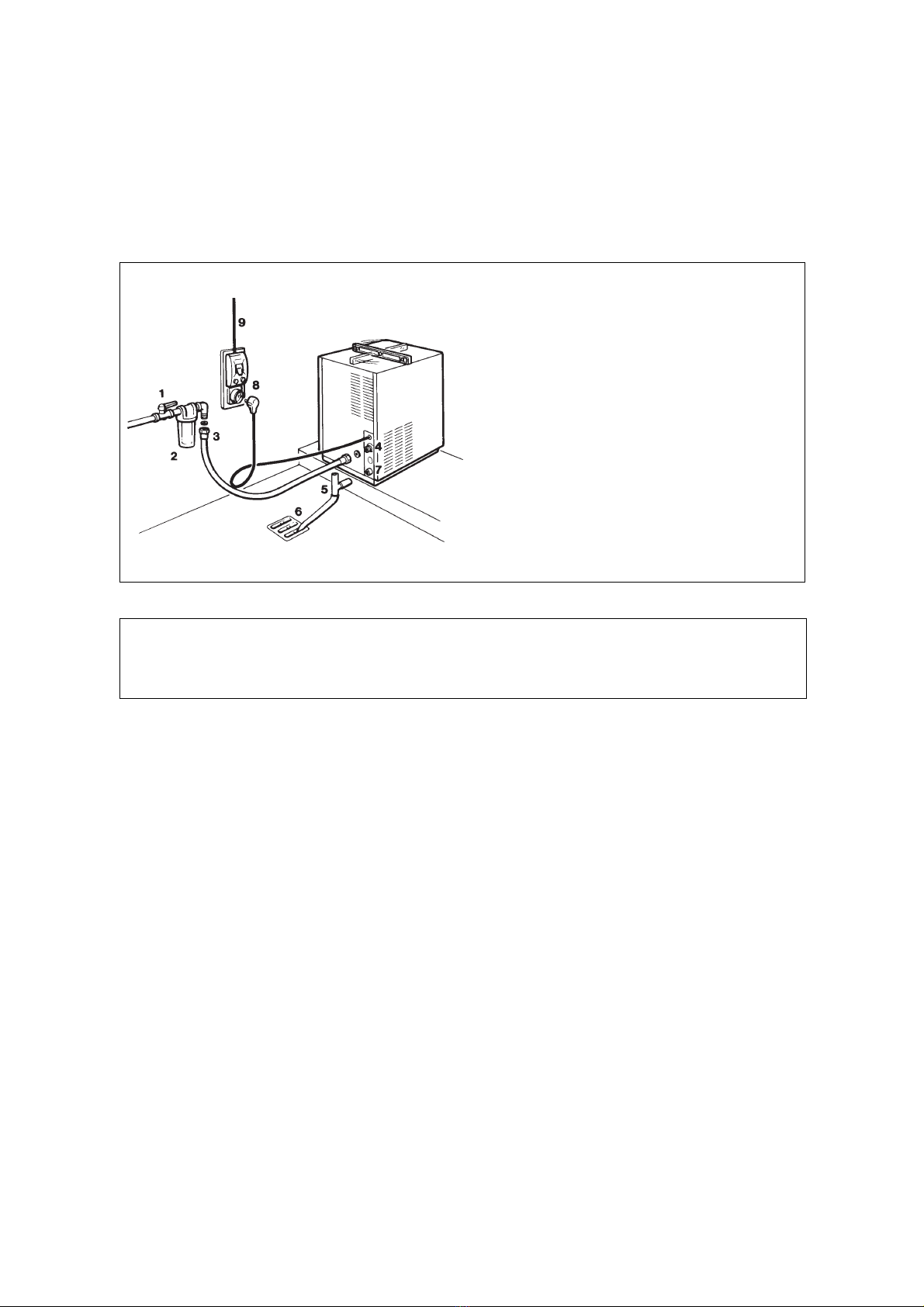
J. Check, during the defrost cycle, that the
incoming water flows correctly into the sump
reservoir in order to refill it and that its surplus
overflows through the overflow drain tube.
K. Checkthetextureoficecubesjustreleased.
They have to be in the right shape with a small
depression of about 5-6 mm in their crown.
Ifnot,waitforthe completionofthe secondcycle
before performing any adjustment.
If the ice cubes require a correction of their
shape, it is possible to modify the length of the
timedfreezingcyclebychangingtheDIPSWITCH
keys setting as illustrated on table C shown in
OPERATING PRINCIPLE.
If the ice cubes are shallow and cloudy, it is
possible that the ice maker runs short of water
during the freezing cycle second phase or, the
quality of the supplied water requires the use of
an appropriate water filter or conditioner.
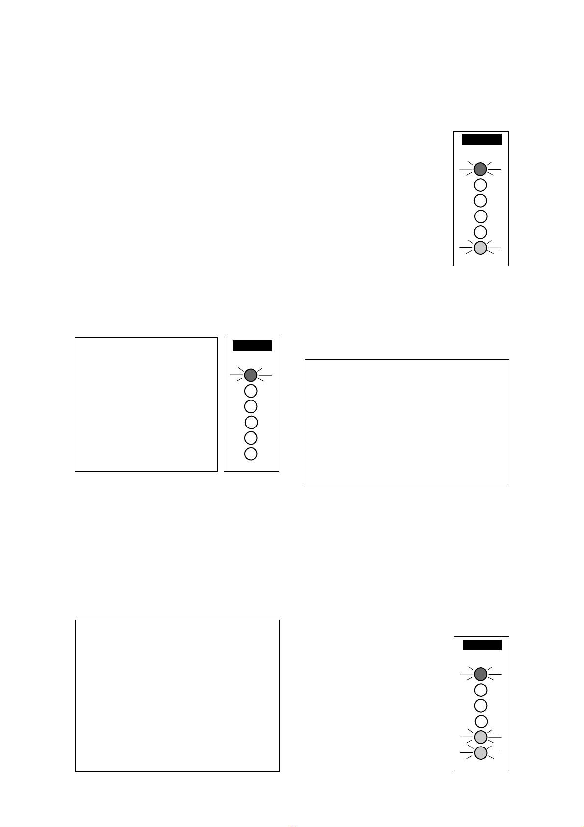
L. To be sure of the correct operation of ice
leveltemperaturesensorlocatedinonesideof
storagebinliner,placeduringthodefrostcycle
one shovel of ice cubes in contact with its
probe.
As the temperature of storage
bin sensor reaches the value
of +2°C (35°F), the ice level
control transmits a signal to
themicroprocessoroftheP.C.
BOARDinorderto stopthe ice
makeroperationjustattheend
of the defrost cycle with the
simul-taneous glowing of the
3rd RED LIGHT, to monitor
theBINFULLsituation(Fig.5).
Withnomoreice cubesintouch
withtheicelevelcontrolthetem-
perature of its probe
progressively rises to reach
+4.5°C (40°F) and at this point the ice machine
restarts to initiate a new freezing cycle with the
simultaneous extinguishing of the 3rd RED
LIGHT.
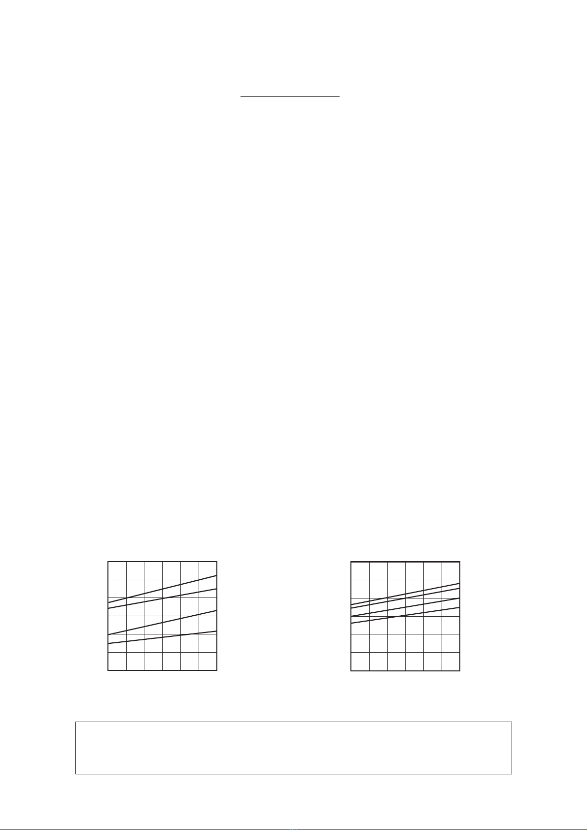
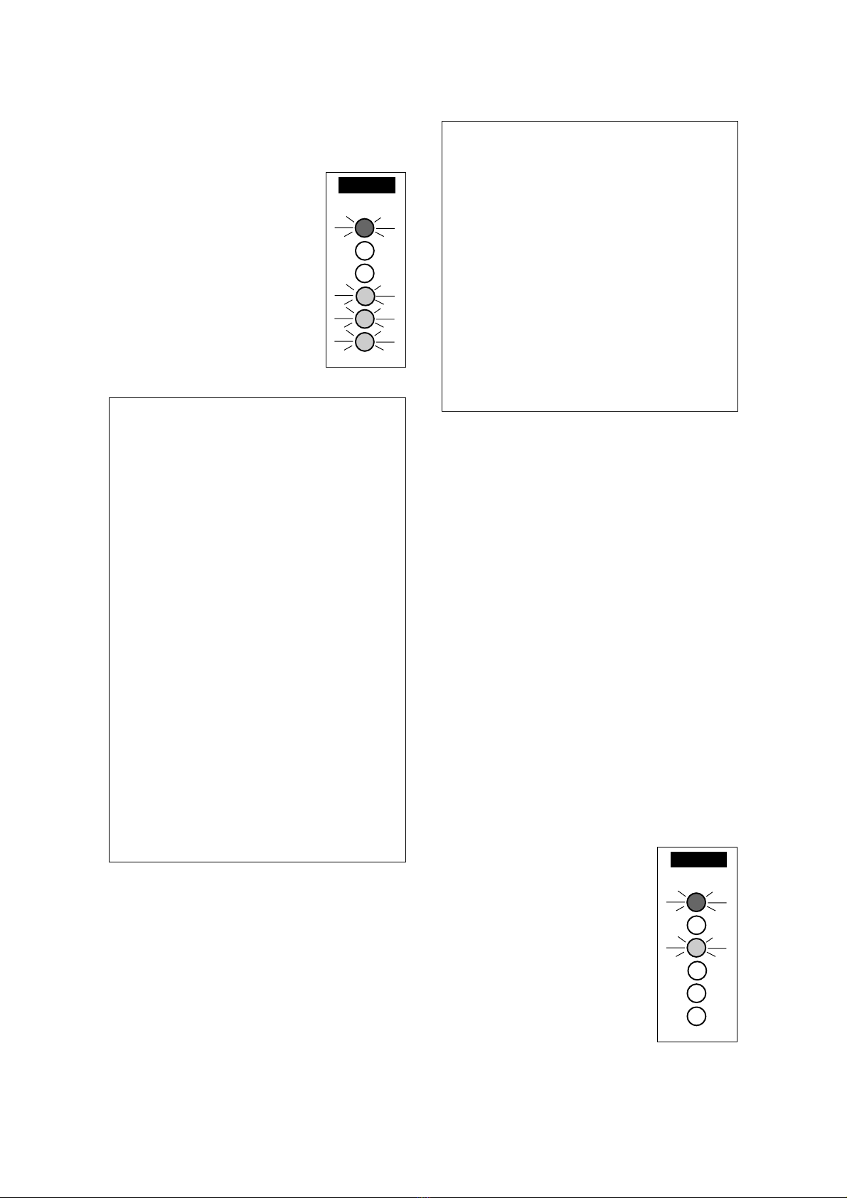
H. The unit remains however in its normal
freezingcyclemodeuntilltheevaporatortempe-
rature detected by the sensor reaches the tem-
perature of -16°C (3°F).
When the evaporator tempera-
turefallsbelowtheabovevalue,
the evaporator temperature
sensor supplies a low voltage
powersignaltotheP.C.BOARD
inordertoactivatetheelectronic
timer.
This one takes over the
controlofthefreezingcycleupto
thecompleteformationoftheice
cubes(Fig.4) withthe lightingup
of the 4th RED LED located just
above the previous lighted one.
NOTE.
Thelengthoftheentirefreezingcycle
is the sum of the lengths of three phases,
two of which, (T1+T2) controlled by the
evaporatortemperaturesensor,whichhas
itsprobeplacedincontactwiththeevaporator
serpentine (Non adjustable), and one (Ta)
by the electronic timer (Adjustable)
incorporated in the P.C.BOARD.
Thelengthsofthefirsttwophases,relatedto
the evaporator temperature and controlled
by its sensor, are:
T1 -The timeelapsed sincethe beginningof
freezing cycle up to when the evaporator
reaches the temperature of 0
°
C (32¯F).
T2 - The time required for the evaporator to
fall from 0
°
C (32
°
F) to -16
°
C (3
°
F).
Thethird timeTa -Time added-isin relation
tooneofthedifferentcombinationsofthefive
keys 3, 4, 5, 6 AND 7 of the DIP SWITCH
located in the front of the P.C.BOARD.
Thecombinationisfactorysetinconsideration
of the ice maker type and of its cooling
version. It is possible, however, to vary the
timedlengthofthefreezingcycle,bychanging
the DIP SWITCH keys settings.
In Table C of PRINCIPLE OF OPERATION
areshownthevarioustimeextensionsofthe
freezingcyclethirdphase Ta,inrelationwith
the different DIP SWITCH keys settings.
I. After about 20-22 minutes from the
beginning of the freezing cycle, in an
hypothetic ambient temperature of 21°C
(70°F), the defrost cycle takes place with
the hot gas and the water inlet valves being
simoultaneously activated.
The electrical components in operation in this
new situation are:
COMPRESSOR
WATER INLET SOLENOID VALVE
HOT GAS VALVE
WATER DRAIN VALVE
and
WATER PUMP for the first 15 seconds.
FIG. 4
FIG. 5
Page 8

O. To check for the correct operation of the
dispensing system place one hand or an ice
bucket close to the photoelectric sensor located
onthefrontside ofthedispensingcompartment.
The auger motor starts immediately turning the
dispensing auger till the photoelectric sensor is
activated by the hand.
NOTE.
TheP.C.Boardisadjustedtoprovide
power to the auger motor for a maximum of
15 seconds just to avoid to overfill the ice
bucket when left in the dispensing
compartment.
TheyellowLED,locatedbesidethegreenone,is
lighted ON while the auger motor is energized.
NOTE.
The CUT-IN RANGE OF THE ICE
LEVEL CONTROL SENSOR can be
adjustedbymeansoftheDIPSWITCHkeys
8 and 9 as shown on table D of PRINCIPLE
OFOPERATION;its cutout setting remains
however at +2
°
C (35
°
F).
M. Remove if fitted the refrigerant service
gauges and re-fit the unit service panels
previously removed.
N. Instruct the owner/user on the general
operation of the ice machine and about the
cleaning and care it requires.
Page 9

PRINCIPLE OF OPERATION
FIG. 6
The length of the second portion of freezing
cycle or time T2 (Not adjustable) is equal to the
time required by the evaporator temperature to
go from 0°C (32°F) to -16°C (3°F). The sensor
will light-up the 4th RED LED.
NOTE.
IncasethetimeT2getslonger than
45 minutes, the unit stops with the glowing
of the 2nd RED WARNING LED.
Alsointhiscase,after havingeliminated the
source of the trip off, to restart the machine
it is necessary first to rotate the program
selectoronRE-SETpositionthenputitagain
onOPERATION or,switch OFFand ONthe
unit at power line Main Switch.
Thethirdportion ortimeTa (Addedtime)ofthe
freezing cycle is controlled by the electronic
timerof P.C.BOARD.Asthe evaporatortempe-
rature reaches the value of -16°C (3°F); the
sensingprobeoftheevaporatorsensor(incontact
with the serpentine) changhes its electrical
resistance causing a low voltage current to flow
tothe P.C. BOARDwhich, thereby,activates an
electronic timer.
NOTE.
The activation of the timer (Time
mode) of P.C. BOARD is signalled by the
glowing of 4th RED LED located in the front
of the P.C. BOARD.
ATTENTION. In case the length of the
second portion of freezing cycle or time
T2, lasts as long as between 35 and 45
minutes, the third portion or time Ta gets
skipped by the P.C. BOARD which puts
the unit directly in the defrost or harvest
cycle.
The length of the third portion of the freezing
cycle (adjustable) is pre-fixed and related to the
setting of the DIP SWITCH keys 3, 4, 5, 6
and 7.
In Table C are indicated the various lengths of
thethirdportionoffreezingcycle(Timemode)in
accordance with the different combinations of
the DIP SWITCH KEYS.
In Table A, herebelow illustrated, are indicated
the DIP SWITCH keys combinations for the
different versions as they are set in the factory.
How it works
In the cube ice makers the water used to make
the ice is kept constantly in circulation by an
electric water pump which primes it to the spray
system nozzles from where it is diverted into the
inverted mold cups of the evaporator (Fig. A).
Asmallquantityofthesprayedwaterfreezesinto
ice; the rest of it cascades by gravity into the
sump assembly below for recirculation.
FREEZING CYCLE
The hot gas refrigerant discharged out from the
compressor (Fig. B) reaches the condenser
where,beingcooleddown,condensesintoliquid.
Flowing into the liquid line it passes through the
drier filter, then it goes all the way through the
capillarytubewhere,duetotheheatexchanging
action, it looses some of its heat content so that
its pressure and temperature are lowered as
well.Nexttherefrigerantentersintotheevaporator
serpentine (which has a larger I.D. then the
capillary) and starts to boil off; this reaction is
emphasized by the heat transferred by the
sprayed water. The refrigerant then increases in
volume and changes entirely into vapor.
The vapor refrigerant then passes through the
suction accumulator (used to prevent that any
small amount of liquid refrigerant may reach the
compressor)andthroughthesuctionline.Inboth
theaccumulatorandthesuctionlineitexchanges
heatwiththerefrigerant flowingintothecapillary
tube (warmer), before to be sucked in the
compressor and to be recirculated as hot
compressed refrigerant gas.
Thefreezingcycleiscontrolledbytheevaporator
temperaturesensor(whichhasitsprobeincontact
with the evaporator serpentine) that determines
thelengthofthefirstandsecondportion ofit; the
starts up of the freezing cycle is signalled by the
glowing of the 6th RED LED.
ThefirstportionlengthortimeT1(Notadjustable)
is equal to the time required by the temperature
sensor to fall to 0°C (32°F). When reached, it is
signalled by the glowing of the 5th RED LED.
NOTE.
If, after 15 minutes,
the evaporator temperature
has not yet reached the value
of 0
°
C(32
°
F)(duetoapartially
ortotalshortage ofrefrigerant
or to a too high condensing
temperature,etc.) thesensor,
through the P.C. BOARD,
causes the unit to stop the
operation with the simoulta-
neousglowingofthe2ndRED
WARNING LED (Fig. 6).
After having eliminated the
source of the unit trip off, to
restart the machine operation
it is necessary first to rotate the program
selector on RE-SET position, then put it
again on to OPERATION position or,
alternatively, switch OFF and ON the hand
disconnect Main Switch. The ice machine
resumes its normal operation by going
through the 5 minutes water filling phase.
Page 10

Page 11

The electrical components in operation during
the freezing cycle are:
COMPRESSOR
FAN MOTOR (in air cooled version)
WATER PUMP
and during the timed phase of freezing cycle
(Time mode) they are joined by the
ELECTRONIC TIMER
On the air cooled versions the refrigerant head
pressure is gradually reduced from a value of
approx.10bar(140 psig),generallyrecordedat
the beginning of the freezing cycle with the unit
at21°C(70°F)ambienttemperature,toaminimun
value of approx. 8 bar (110 psig) just at the end
of the freezing cycle few seconds before the
starting of the defrost cycle.
The declining of the pressure is subordinated to
thereductionoftheevaporatingpressure,caused
by the progressive growth of the ice thickness
into the inverted cup molds and to the flow of air
drown through the air cooled condenser by the
fan motor.
The above values are in relation as well to the
ambient temperature of the ice maker site and
they are subject to rise with the increase of this
temperature.
On the water cooled versions the refrigerant
headpressureisstableat9bar(125psig)being
controlled by a water regulating valve.
Withthe unit installedin anormal location(21°C
ambient temperature) at the start of the freezing
cycletherefrigerantsuctionorlo-pressurelowers
rapidlyto1bar(14psig)thenitdeclinesgradually
- in relation with the growing of the ice thickness
- to reach, at the end of the cycle, approx. 0÷0.1
bar (0÷2 psig) withthe cubes fullyformed inthe
cup molds.
Thetotallengthofthefreezingcyclerangesfrom
20 to 22 minutes.
DEFROST OR HARVEST CYCLE
As the electronic timer has carried the system
throughoutthethirdphaseoffreezingcycleoras
soon as the second phase T2 is over (when its
lengthhasbeenaslong as35to 45minutes)the
defrost cycle starts.
DIP SWITCH 1 2345 678910
Air Cooled ON OFF OFF OFF ON OFF ON ON ON OFF
Water cooled ON OFF OFF ON OFF OFF ON ON ON OFF
TAB. A DIP SWITCH KEYS FACTORY SETTING COMBINATIONS
NOTE.
The length of the defrost cycle (not
adjustable) is related to the length of the
secondphaseoffreezingcycleT2asdetailed
in Table B.
The electrical components in operation during
this phase are:
COMPRESSOR
WATER INLET SOLENOID VALVE
HOT GAS SOLENOID VALVE
WATER DRAIN VALVE
and
WATER PUMP for the first 15 seconds.
The incoming water, passing through the water
inlet valve and its flow control (Fig. C) runs over
the evaporator platen and then flows by gravity
through the dribbler holes down into the sump/
reservoir.
Thewaterfillingthesump/reservoirforcespartof
the surplus water from the previous freezing
cycleto goout tothe wastethrough theoverflow
pipe. This overflow limits the level of the sump
water which will be used to produce the next
batch of ice cubes.
Meanwhile,therefrigerantashotgas,discharged
from the compressor (Fig. D) flows through the
hot gas valve directly into the evaporator
serpentine by-passing the condenser.
The hot gas circulating into the serpentine of the
evaporator warms up the copper molds causing
the defrost of the ice cubes. The ice cubes,
released from the cups, drop by gravity onto a
slanted cube chute, then through a curtained
opening they fall into the storage bin.
Thewaterpumpremainsinoperation,duringthe
first 15-20 seconds of the defrost cycle, to pump
out, trough the opened water drain valve, the
remainingwater(reachofmineralsanddeposits)
of the previous freezing cycle.
NOTE.
The length of the defrost cycle (not
adjustable) changes in accordance with the
durationofthesecondportionofthefreezing
cycle T2 .
At the end of the defrost cycle, both the hot gas
andthewaterinletvalvescloseandthemachine
starts again a new freezing cycle.
Page 12

OPERATION - ELECTRICAL SEQUENCE
The following charts illustrate which switches
and which components are ON or OFF during a
particular phase of the icemaking cycle.
BEGINNING FREEZE (Time T1 and T2)
Electrical components (Loads).... ON OFF
Compressor..................................... •
Water Pump .................................... •
Fan Motor (Air cooled only)............. •
Hot Gas Valve ................................. •
Water Inlet Valve............................. •
Water drain valve ............................ •
P.C.Board Relay 1 Coil ................... •
P.C.Board Relay 2 & 3 Coil............. •
Electronic Timer .............................. •
Electronic Controls & Sensors .... ON OFF
Evaporator Sensor .......................... •
Ice Level Sensor ............................. •
TIMED FREEZE (Time Ta)
Electrical components (Loads).... ON OFF
Compressor..................................... •
Water Pump .................................... •
Fan Motor (Air cooled only)............. •
Hot Gas Valve ................................. •
Water Inlet Valve............................. •
Water drain valve ............................ •
P.C.Board Relay 1 Coil ................... •
P.C.Board Relay 2 & 3 Coil............. •
Electronic Timer .............................. •
Electronic Controls & Sensors .... ON OFF
Evaporator Sensor .......................... •
Ice Level Sensor ............................. •
HARVEST
Water Drain Phase
Electrical components (Loads).... ON OFF
Compressor..................................... •
Water Pump .................................... •
Fan Motor (Air cooled only)............. •
Hot Gas Valve ................................. •
Water Inlet Valve............................. •
Water drain valve ............................ •
P.C.Board Relay 1 & 3 Coil............. •
P.C.Board Relay 2 Coil ................... •
Electronic Timer .............................. •
Electronic Controls & Sensors .... ON OFF
Evaporator Sensor .......................... •
Ice Level Sensor ............................. •
HARVEST
Water Filling Phase
Electrical components (Loads).... ON OFF
Compressor..................................... •
Water Pump .................................... •
Fan Motor (Air cooled only)............. •
Hot Gas Valve ................................. •
Water Inlet Valve............................. •
Water drain valve ............................ •
P.C.Board Relay 1 & 3 Coil............. •
P.C.Board Relay 2 Coil ................... •
Electronic Timer .............................. •
Electronic Controls & Sensors .... ON OFF
Evaporator Sensor .......................... •
Ice Level Sensor ............................. •
OPERATING CHARACTERISTICS
On air cooled models, during the freezing cycle,
the discharge pressure will slowly decline as the
unitfreezes ice andat thesame timethe suction
pressure will also decline, reaching its lowest
point just before harvest. Compressor amps
experience a similar drop.
Onwatercooledmodels,thedischargepressure
is maintened during the freeze cycle between 8
and10bar (110÷140psig)bythe combinationof
a pressure control and a water inlet solenoid
valve.However,suctionpressureandcompressor
ampswillstilldeclineasthemachinefreezesice.
Freeze Cycle
Average Discharge Pressure
A/C: 8÷10 bar (110÷140 psig)
Average Discharge Pressure
W/C: 9 bar (125 psig)
Suction Pressure
End Freeze Cycle: 0÷0.1 bar (0÷2 psig)
REFRIGERANT METERING DEVICE:
capillary tube
REFRIGERANT CHARGE (R 134a)
Air Cooled Water Cooled
320 gr (11.5 oz) 280 gr (10 oz)
Page 13

D. P.C. BOARD (Data processor)
The P.C. BOARD, fitted in its plastic box located
in the rear of the unit, consists of two separated
printed circuits one at high and the other at low
voltageintegratedwithaprogramselector;ofsix
alignedLEDSmonitoringtotheserviceengineer
theoperationofthemachine;ofoneDIPSWITCH
with ten keys; of input terminals for the leads of
the three sensor probes and of input and output
terminalsfor theleadsof theicemakerelectrical
wires.
The P.C. BOARD is the brain of the system and
it elaborates, through its Micro Processor, the
signalsreceivedfrom thetwo sensorsin orderto
control the operation of the different electrical
componentsoftheicemaker(compressor,water
pump, solenoid valves, etc.).
By turning the program selector it is possible to
put the unit in the following different situations:
CLEANING/RINSING. The water pump is the
only electrical component in operation and it
must be used during the cleaning or the rinsing
procedure of the water system of ice machine.
STAND BY. The unit remain under electrical
powerbutOUTofoperation.Itcanbeusedbythe
service engineer in order to stop the unit during
the service and inspection operations.
IN OPERATION. Theunit isrunning throughthe
freezinganddefrostcyclesstoppingautomatically
only at full bin situation.
RE-SET. To be selected to resume the unit
operationwhentheicemakershutsoffduetothe
interventionofthesecurityoftheP.C.BOARDin
relation to the exceeding time of freezing cycle
portion T1 and T2.
The six LEDS (not visibles trough the panel)
placed in a vertical row in the front of the P.C.
BOARD,monitor, fromthetop tothe bottom,the
following situations:
GREEN LIGHT
Unit under electrical power
RED LIGHT Unit shut-off due to P.C. BOARD
security (T1 > 15' o T2 > 45')
RED LIGHT Unit shut-off at full storage bin
RED LIGHT Evaporator sensor at -16°C
(3°F)
RED LIGHT Evaporator sensor at 0°C (32°F)
RED LIGHT Compressor under power
COMPONENTS DESCRIPTION
A. EVAPORATOR TEMPERATURE
SENSOR
The evaporator temperature sensor probe,
locatedincontactwiththeevaporatorserpentine,
detects the dropping of the evaporator tempera-
ture during the freezing cycle and signals it by
supplyingacurrentflowtotheMicroProcessorof
P.C. BOARD.
According to the current signal and to after how
longthisisreceived,theMicroProcessormayor
notgivetheconsenttotheicemakertocomplete
the freezing cycle.
The low voltage current transmitted, from the
evaporator temperature sensor to the P.C.
BOARD, is signalled by the lighting up of the
fourth (Time T1) and fifth (Time T2) RED LED
placed in the front of the P.C. BOARD to inform
the service engineer, of the normal (regular)
progressing of the freezing cycle.
B. ICE BIN LEVEL SENSOR
Theicebinlevel temperaturesensor,securedto
one of the storage bin walls, stops the operation
oftheentireicemakerjustattheendofdefrost
cyclewhenitssensingprobe(incontactwiththe
stored ice) reaches the temperature of +2°C
(35°F) lighting up, in the meantime, the third
RED LED.
Oncetheiceisremovedfromthesensingprobe,
its temperature progressively rise up and as it
reaches the value of +4.5°C (40°F) the ice bin
leveltemperaturesensortransmitsalowvoltage
current flow to the P.C. BOARD so to restart the
operation of the unit.
NOTE.
The ice maker, after the interruption
of its operation due to the ice level control
cut-out, always restarts from the beginnig of
the freezing cycle.
BychangingthecombinationoftheDIPSWITCH
Keysnumber8and9itispossibletochangethe
rangeoftheicelevelcontroltemperaturesensor.
This is shown on table D, keeping its cut out
temperature always at +2°C (35°F).
C. PHOTOELECTRIC SENSOR
The photoelectric sensor, located behind the
dispenserplasticpanel,iselectricallyconnected
to the P.C. BOARD so to provide power to the
auger drive motor when the ice backet is place
close to its sensitivity probe.
As soon as the ice backet is removed from the
dispensing compartment the auger motor stops
immediately.
NOTE.
Maximumcontinuousoperating time
of the auger motor is 15 seconds controlled
by the P.C. BOARD.
Page 14

The Micro Processor of the P.C. BOARD has
alsotheimportantfunctiontoestablishthelength
ofthedefrostcycleTsinrelationwiththeduration
ofthe secondphase ofthefreezing cycleor time
T2 as shown on table B.
E. DIP SWITCH
The P.C.BOARD which controls the entire
operation of the ice maker, has a DIP SWITCH
with ten switching keys which allow to set up
the micro processor program in order to extend
or to shorten the length of freezing cycle in
relation to the different models and versions of
icemachines andtomodify thesensingrange of
the ice bin level temperature sensor.
The 1st DIP SWITCH key is used to supply
power to the water pump during the first 15-20
seconds of the defrost cycle to pump out all
remaining water from the sump tank when is set
to ON position.
The 2nd DIP SWITCH key allows to make a
rapid check up (auto-diagnosis) of the P.C.
BOARDoutput connections(compressor, water
pump,fanmotor,waterinletandhotgassolenoid
valves) energizing them in rapid sequence (2
seconds) one by one.
DURING THE AUTOMATIC OPERATION OF
THE ICE MAKER THIS KEY MUST BE SET IN
OFF POSITION.
ATTENTION. The check up of the
P.C.BOARDoutputmustbe performed in
averyshorttimeinordertoavoidfrequent
start and stop (every few seconds) of the
electricalcomponentswhichmaydamage
them especially the compressor.
The setting of the DIP SWITCH keys 3, 4, 5, 6
and 7 determines the length of the 3rd phase of
freezingcycle(controlledbytheelectronictimer)
as detailed in table C.
34567Ta 34567Ta
min. min.
ON ON ON ON ON 0 OFF ON OFF OFF ON 13
OFF ON ON ON ON 1 ON OFF OFF OFF ON 14
ON OFF ON ON ON 2 OFF OFF OFF OFF ON 15
OFF OFF ON ON ON 3 ON ON ON ON OFF 16
ON ON OFF ON ON 4 OFF ON ON ON OFF 17
OFF ON OFF ON ON 5 ON OFF ON ON OFF 18
ON OFF OFF ON ON 6 OFF OFF ON ON OFF 19
OFF OFF OFF ON ON 7 ON ON OFF ON OFF 20
ON ON ON OFF ON 8 OFF ON OFF ON OFF 21
OFF ON ON OFF ON 9 ON OFF OFF ON OFF 22
ON OFF ON OFF ON 10 OFF OFF OFF ON OFF 23
OFF OFF ON OFF ON 11 ON ON ON OFF OFF 24
ON ON OFF OFF ON 12 OFF ON ON OFF OFF 25
TAB. C LENGHTS OF TIMED PORTION OF FREEZING CYCLE ACCORDING TO
THE DIP SWITCH SETTING COMBINATIONS
TAB. B LENGTH OF THE DEFROST CYCLE Ts ACCORDING TO THE LENGTH OF T2
T2 Ts
T2 < 5' 210"
5' < T2 < 6' 195"
6' < T2 < 6' 30" 180"
6' 30"< T2 < 7' 165"
7' < T2 < 8' 150"
8' < T2 < 9' 135"
9' < T2 < 10' 30" 120"
10' 30" < T2 < 12' 105"
12' < T2 90"
Page 15

The DIP SWITCH keys 8 and 9 setting
determinesthe rangebetween cutinand cutout
temperature of the ice bin level temperature
sensor as specified in table D.
The 10th DIP SWITCH is used to control the
-13°C (9°F) evaporating temperature and must
be left always in OFF position.
F. WATER SPRAY SYSTEM
Throughitsnozzles,thewaterpumped,issprayed
in each individual cup to be frozen into ice.
It consists of one spray platform which has six
spray nozzles each.
G. WATER PUMP
Thewaterpumpoperatescontinuallythroughout
the freezing cycle priming the water from the
sumpto thespraysystemand throughthe spray
nozzles sprays it into the inverted cup molds to
be frozen into crystal clear ice cubes.
Itisrecommendedthatthepumpmotorbearings
be checked at least every six months.
H. WATER INLET SOLENOID VALVE - 3/4
MALE FITTING
Thewaterinletsolenoid valveisactivatedbythe
Micro Processor of the P.C. BOARD during the
first 5 minutes of water filling phase and as well
during the defrost cycle.
When energized it allows a metered amount of
incomingwatertoflowovertheevaporatorcavity
to assist the hot gas in defrosting the ice cubes.
The water running over the evaporator cavity
dropsbygravity,throughthedribblerholesofthe
platen, into the sump reservoir where it will be
sucked by the water pump and primed to the
spray system.
I. HOT GAS SOLENOID VALVE
The hot gas solenoid valve consists basically of
two parts: the valve body and the valve coil.
8 9 DELTA T (°C)
ON ON 1
OFF ON 1,5
ON OFF 2
OFF OFF 2,5
TAB. D ICE LEVEL SENSOR CONTROL TEMPERATURE RANGE ACCORDING TO
THE DIP SWITCH SETTING COMBINATIONS
Locatedonthehotgasline,thisvalveisenergized
through the Micro Processor of P.C. BOARD
during the defrost cycle and during the water
filling phase.
During the defrost cycle the hot gas valve coil is
activated so to attract the hot gas valve stem in
order to give way to the hot gas discharged from
thecompressortoflowdirectlyintotheevaporator
serpentine to defrost the formed ice cubes.
J. FAN MOTOR (Air cooled version)
Thefanmotor,electricallyconnectedtothehead
pressurecontrol, operatesduringfreezingcycle
to draw cooling air through the condenser fins
keepingthethecondensingtemperatureandthe
condensing pressure between the operating
values according to the ambient temperature.
K. COMPRESSOR
The hermetic compressor is the heart of the
refrigerant system and it is used to circulate and
retrieve the refrigerant throughout the entire
system. It compresses the low pressure
refrigerant vapor causing its temperature to rise
and become high pressure hot vapor which is
then released through the discharge valve.
L. AUGER DRIVE MOTOR
The Auger Motor electrically connected to the
PC BOARD is located behind the upper front
panelandisusedto movetheice cubestowards
thedispensingchuteplacedontheupperside of
the dispensing system.
M. WATER REGULATING VALVE
This valve controls the head pressure in the
refrigerantsystembyregulatingtheflowofwater
going to the condenser.
As pressure increases, the water regulating val-
ve opens to increase the flow of cooling water.
Page 16

ADJUSTMENT PROCEDURES
SMALL
IDENTATION
LITTLE OR NO
ICE IN CENTER
OF CUBE
THICK BULGE
SOLID ICE
NORMAL SIZE-AHAPE
SHALLOW SIZE
OVER SIZE
4. Observe the ice cubes in the next two
harvests and repeat eventually steps 2 and 3
above until proper ice cubes size is achieved.
See figure.
A. ADJUSTMENT OF THE CUBE SIZE
CAUTION. Before performing actual
adjustment of the cube size, check other
possible causes for cube size problems,
refertotheServiceDiagnosisSectionfor
problem review and analysis.
Do not perform any adjustment till the
icemaking system has progressed
through several complete freezing and
harvestcycle,toobservesizeandquality
of ice cubes and whether or not the cube
size problem exists.
I. Ifthecubesareshallowsize(Indentationis
too deep) probably the length of the third phase
of the freezing cycle is too short so, to extend
such length you have to:
1. Locate the DIP SWITCH on the front of the
P.C.Board.
2. Take note of the combination of the DIP
SWITCH KEYS 3, 4, 5, 6 and 7 and check the
corrispondinglength offreezing cycle3rdphase
as shown on Table C.
3. Change the same DIP SWITCH KEYS
settingsothatitwillcorrespondtothecombination
on table C coming next to the one remarked at
step 2.
This will allow an extension of the freezing cycle
of one more minute.
4. Observe the ice cubes in the next two
harvests and eventually repeat steps 2 and 3
above until proper ice cubes size is achieved.
See figure.
II. If the cubes are oversize size (Indentation
is too full) probably the length of the second
phase of the freezing cycle is too long.
To shorten such length you have to:
1. Locate the DIP SWITCH on the front of the
P.C.Board.
2. Take note of the combination of the DIP
SWITCH KEYS 3, 4, 5, 6 and 7 and check the
corrispondinglength offreezing cycle3rdphase
as shown on Table C.
3. Change the same DIP SWITCH KEYS
settingsothatitwillcorrespondtothecombination
on table C pre-ceding the one remarked at
step 2.
This will reduce an the freezing cycle length of
one minute.
Page 17

WIRING DIAGRAM
AIR COOLED - 230/50/1 COLOUR CABLES
m = brown
n = black
bc = light blue
gv = yellow-green
A) POWER CABLE
B) FAN MOTOR
C) COMPRESSOR MOTOR
D) PUMP
E) WATER INPUT EL. VALVE
F) DEFROST EL. VALVE
G) AUGER GEAR-MOTOR
H) BIN TEMP. PROBE
I) EVAPORATOR PROBE
L) ICE PHOTOSWITCHES
M) ELECTRONIC CARD
O) FAN PRESSURE SWITCH
P) ANTI-STRIP
Q) START CAPACITOR
R) START RELAY
S) TERMINAL BOARD
T) COMPRESSOR BOX
V) WATER OUT EL. VALVE
W) THERMOSTAT
Z) LEDS
Page 18

WIRING DIAGRAM
WATER COOLED - 230/50/1 COLOUR CABLES
m = brown
n = black
bc = light blue
gv = yellow-green
A) POWER CABLE
B) FAN MOTOR
C) COMPRESSOR MOTOR
D) PUMP
E) WATER INPUT EL. VALVE
F) DEFROST EL. VALVE
G) AUGER GEAR-MOTOR
H) BIN TEMP. PROBE
I) EVAPORATOR PROBE
L) ICE PHOTOSWITCHES
M) ELECTRONIC CARD
O) MAX PRESSURE SWITCH
P) ANTI-STRIP
Q) START CAPACITOR
R) START RELAY
S) TERMINAL BOARD
T) COMPRESSOR BOX
V) WATER OUT EL. VALVE
W) THERMOSTAT
Z) LEDS
Page 19
Table of contents
Other Icematic Ice Maker manuals

Icematic
Icematic M Series User manual

Icematic
Icematic E21 User manual

Icematic
Icematic E35 User manual

Icematic
Icematic F 125C User manual

Icematic
Icematic N21 User manual

Icematic
Icematic E Series User manual

Icematic
Icematic F 80 C User manual

Icematic
Icematic N 132M User manual

Icematic
Icematic N 132M Operating instructions

Icematic
Icematic N25S User manual