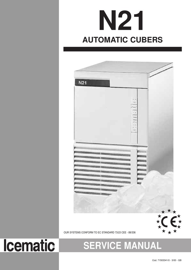
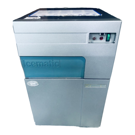
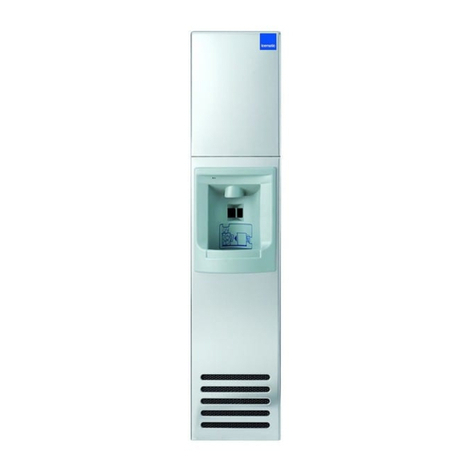
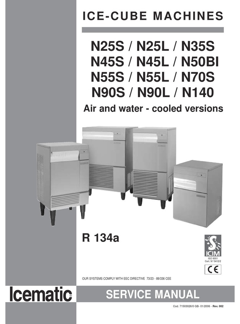
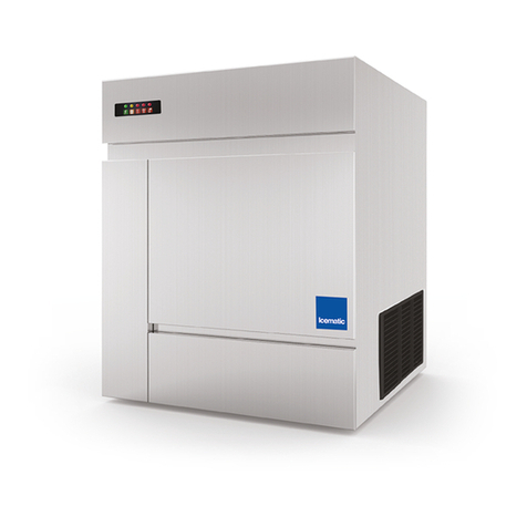
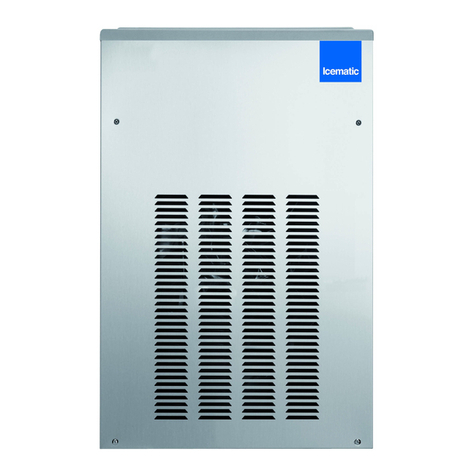
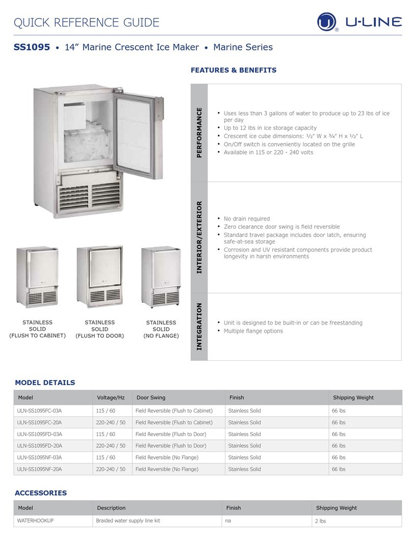
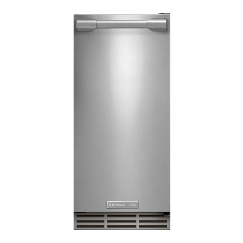
Icematic M Series User manual

S rvic Manual

Gentile Cliente,
La ringraziamo per aver preferito uno dei
nostri prodotti, frutto di lunga esperienza
e di una continua ricerca per un prodotto
superiore in termini di affidabilità,
prestazioni e sicurezza.
In questo manuale troverà tutte le
informazioni ed i consigli per poter
utilizzare il suo prodotto nel massimo
della sicurezza ed efficienza.
ear Customer,
We would like to thank you for having
chosen our products, the result of long
experience and continuous research for a
superior product in terms of reliability,
performance and safety.
This manual will supply all of the
information and advice for the efficient
use of your product in complete safety.
Cher Client,
Nous vous remercions d’avoir choisi notre
produit, fruit d’une longue expérience et
d’une recherche permanente d’un produit
supérieur en termes de fiabilité, de
prestations et de sécurité.
ans ce manuel vous trouverez toutes les
informations et les conseils pour pouvoir
utiliser votre produit avec une sécurité et
une efficacité optimales.
Sehr geehrter Kunde!
Wir danken Ihnen für Ihre Wahl eines
unserer Produkte, welches das Ergebnis
einer langen Erfahrung und stetiger
Forschungsarbeit ist. ank dieser konnte
ein Produkt entwickelt werden, das ein
hohes Maß an Verlässlichkeit,
Leistungsfähigkeit und Sicherheit bietet.
In diesem Handbuch finden Sie sämtliche
Informationen und Ratschläge, damit Sie
das Produkt mit maximaler Sicherheit und
Effizienz nutzen können.
Estimado cliente:
Le agradecemos por elegir nuestros
productos, fruto de la gran experiencia y
de la investigación constante para
obtener un producto superior en
términos de fiabilidad, rendimientos y
seguridad.
En este manual, encontrará todos los
datos y consejos para poder utilizar el
producto en sus máximos niveles de
seguridad y eficiencia.

PREFACE
• This manual is an integral part of the pro-
duct, providing all the information required
to ensure correct installation, operation and
maintenance of the machine.
•Rea the manual carefully, making refe-
rence to it for machine operation. Keep the
manual in a safe place where it can be ac-
cessed by all authorised operators (instal-
lers, operators and service personnel).
• The machine has been constructed in com-
pliance with the directives 2006/95/CEE
(low-voltage), 2004/108/CEE (electroma-
gnetic compatibility) and 2006/42/CEE
(machines; for certain models only).
• Installation must be performed in com-
pliance with National and Local Standards,
by professionally qualified staff and accor-
ding to the manufacturer's instructions.
• Any contractual and extra-contractual lia-
bility of the manufacturer is excluded due
to damage caused by errors during instal-
lation and use and, however, failure to com-
ply with the National and Local Standards
in force and the instructions supplied by
the manufacturer.
• Make sure that the supplied or specified
components are used.
• Before performing any cleaning or mainte-
nance operation, disconnect the appliance
from the electric power supply mains by
operating on the system switch and/or the
product switch.
• In the event of faults and/or bad functio-
ning, deactivate the appliance and do not
attempt any repairs or direct intervention.
CAU ION
HE FOLLOWING OPERA IONS
AND HOSE HIGHLIGH ED
BY HIS SYMBOL MUS NO BE
PERFORMED BY HE APPLIANCE USER
In particular:
•Electrical connections
• Water connections
• Installation
• esting
• Repairing machine components
• Disassembly of the appliance
and/or its components
• Adjustments and calibration
• Cleaning the appliance and maintenance of:
- Electrical parts,
- Electronic parts,
- Mechanical parts,
- Refrigeration system parts
HE EX WI H HIS SYMBOL
IS OF PAR ICULAR IMPOR ANCE
OR PO EN IAL DANGER SIGNALS
NO A claries the current operations
i

MARCHI - MARKS
Via del Lavoro,9 - C.P. 172
I - 31033 Castelfranco Veneto (TV)
ITALY EU
Tel. +39 0423 738452
Fax +39 0423 722811
MIN MAX
10°C (50°F) 40°C (104°F)
5°C (41°F) 35°C (95°F)
-10% +10%
1 Bar (14 psi) 5 Bar (70 psi)
7
W
W
+C°
- C°
21°C
32°C
PRODUZIONE DI GHIACCIO - ICE PRODUCTION kg/24h - lbs/24h
DIMENSIONI - DIMENSIONS
24 h
Dice Cube - 10 g
22 x 22 x 24 mm
DEPOSITO - SLOPE BIN
Half-Large Cube - 6 g
10 x 29 x 24 mm
Large Cube - 17 g
29 x 29 x 24 mm
CONTROLLO - CONTROL
www.castelmac.it
Raffreddamento ad aria Air Cooled Unit Raffreddamento ad acqua - Water Cooled Unit
T
emp. aria
Air Temp. Temp. acqua / Water Temp. T
emp. aria
Air Temp. Temp. acqua / Water Temp.
°C 32° 21° 15° 10° °C 32° 21° 15° 10°
°F 90° 70° 60° 50° °F 90° 70° 60° 50°
10° 129 147 150 154 10° 123 131 134 136
50° 284 323 330 340 50° 271 289 295 300
21° 112 127 133 138 21° 111 121 126 128
70° 247 281 239 305 70° 245 267 278 282
32° 96 107 110 113 32° 102 110 117 119
90° 212 236 242 249 90° 225 243 258 262
38° 79 87 95 98 38° 100 108 115 116
100° 173 193 209 215 100° 221 238 254 256
M132
Fabbricatori di ghiaccio in cubetti : M132 - M192 -M202 - M302 - M402 - M502
Ice Cube Machines : M132 - M192 -M202 - M302 - M402 - M502
154kg - 339lbs
R404A
220-240/50/1
LxPxH(mm): 560 x 620 x 575
WxDxH(in): 22" x 24 7/16" x 22 10/16"
DATI TECNICI - SPECIFICATIONS
COMP. W ABS. W FUSE Kwh/100Kg l/h kg Lbs kg Lbs
M132 A
1637 850 10 15.9 7.0 53 117 65 143
M132 W 1637 750 10 12.1 107.0 53 117 65 143
COND.
168 D105 - D155
336
Pulsante Reset/Lavaggio
Button Reset/Washing
Allarme Alta Pressione
High Pressure Alarm
Allarme
Alarm
Deposito Pieno/Lavaggio
Storage Full / Washing
In Funzionamento
Operating
Alimentazione
Powered
336
D205 - D255 (KM205-255)

MARCHI - MARKS
Via del Lavoro,9 - C.P. 172
I - 31033 Castelfranco Veneto (TV)
ITALY EU
Tel. +39 0423 738452
Fax +39 0423 722811
MIN MAX
10°C (50°F) 40°C (104°F)
5°C (41°F) 35°C (95°F)
-10% +10%
1 Bar (14 psi) 5 Bar (70 psi)
7
W
W
+C°
- C°
21°C
32°C
PRODUZIONE DI GHIACCIO - ICE PRODUCTION kg/24h - lbs/24h
DIMENSIONI - DIMENSIONS
24 h
Dice Cube - 10 g
22 x 22 x 24 mm
DEPOSITO - SLOPE BIN
Half-Large Cube - 6 g
10 x 29 x 24 mm
Large Cube - 17 g
29 x 29 x 24 mm
CONTROLLO - CONTROL
www.castelmac.it
Raffreddamento ad aria Air Cooled Unit Raffreddamento ad acqua - Water Cooled Unit
T
emp. aria
Air Temp. Temp. acqua / Water Temp. T
emp. aria
Air Temp. Temp. acqua / Water Temp.
°C 32° 21° 15° 10° °C 32° 21° 15° 10°
°F 90° 70° 60° 50° °F 90° 70° 60° 50°
10° 198 218 222 225 10° 173 193 202 205
50° 437 481 490 496 50° 381 425 446 453
21° 177 197 201 204 21° 161 183 194 197
70° 390 434 443 450 70° 356 404 427 435
32° 140 160 164 167 32° 158 176 184 190
90° 309 353 362 368 90° 348 388 406 419
38° 122 142 146 149 38° 145 165 175 183
100° 269 313 322 329 100° 321 365 386 404
M192
Fabbricatori di ghiaccio in cubetti : M132 - M192 -M202 - M302 - M402 - M502
Ice Cube Machines : M132 - M192 -M202 - M302 - M402 - M502
225kg - 496lbs
R404A
220-240/50/1
COND.
130 D105 - D155
204
Pulsante Reset/Lavaggio
Button Reset/Washing
Allarme Alta Pressione
High Pressure Alarm
Allarme
Alarm
Deposito Pieno/Lavaggio
Storage Full / Washing
In Funzionamento
Operating
Alimentazione
Powered
325
D205 - D255 (KM205-255)
DATI TECNICI - SPECIFICATIONS
COMP. W ABS. W FUSE Kwh/100Kg l/h kg Lbs kg Lbs
M192 A
2348 1100 16 14.7 11 68 150 80 176
M192 W 2348 1000 16 11.1 126 68 150 80 176
LxPxH(mm): 560 x 620 x 660
WxDxH(in): 22" x 24 7/16" x 26"
&
'
%
$
#
+%'&412#4'#
9#6'4%11.'&
#+4%11.'&

MARCHI - MARKS
Via del Lavoro,9 - C.P. 172
I - 31033 Castelfranco Veneto (TV)
ITALY EU
Tel. +39 0423 738452
Fax +39 0423 722811
MIN MAX
10°C (50°F) 40°C (104°F)
5°C (41°F) 35°C (95°F)
-10% +10%
1 Bar (14 psi) 5 Bar (70 psi)
7
W
W
+C°
- C°
21°C
32°C
PRODUZIONE DI GHIACCIO - ICE PRODUCTION kg/24h - lbs/24h
DIMENSIONI - DIMENSIONS
24 h
Dice Cube - 10 g
22 x 22 x 24 mm
DEPOSITO - SLOPE BIN
Half-Large Cube - 6 g
10 x 29 x 24 mm
Large Cube - 17 g
29 x 29 x 24 mm
CONTROLLO - CONTROL
www.castelmac.it
#
$
%
&
'
+%'&412#4'#
9#6'4%11.'&
#+4%11.'&
Raffreddamento ad aria Air Cooled Unit Raffreddamento ad acqua - Water Cooled Unit
T
emp. aria
Air Temp. Temp. acqua / Water Temp. T
emp. aria
Air Temp. Temp. acqua / Water Temp.
°C 32° 21° 15° 10° °C 32° 21° 15° 10°
°F 90° 70° 60° 50° °F 90° 70° 60° 50°
10° 185 215 230 240 10° 175 200 215 220
50° 408 474 507 529 50° 386 441 474 485
21° 175 200 215 220 21° 170 195 210 215
70° 386 441 474 485 70° 375 430 463 474
32° 135 155 160 165 32° 160 185 192 197
90° 298 342 353 365 90° 353 408 423 434
38° 120 133 138 140 38° 155 180 185 190
100° 265 293 302 309 100° 342 397 408 419
M202
Fabbricatori di ghiaccio in cubetti : M132 - M192 -M202 - M302 - M402 - M502
Ice Cube Machines : M132 - M192 -M202 - M302 - M402 - M502
240kg - 529lbs
R404A
220-240/50/1
COND.
140 D205 - D255
234
Pulsante Reset/Lavaggio
Button Reset/Washing
Allarme Alta Pressione
High Pressure Alarm
Allarme
Alarm
Deposito Pieno/Lavaggio
Storage Full / Washing
In Funzionamento
Operating
Alimentazione
Powered
370
D305(KM305)- D405(KFM404)-
D505(KFM505)
DATI TECNICI - SPECIFICATIONS
COMP. W ABS. W FUSE Kwh/100Kg l/h kg Lbs kg Lbs
M202 A
2348 1100 16 14.8 12 70 154 85 187
M202 W 2348 1000 16 10.6 128 70 154 85 187
LxPxH(mm): 760 x 620 x 575
WxDxH(in): 29 15/16" x 24 7/16" x 22 10/16"

MARCHI - MARKS
Via del Lavoro,9 - C.P. 172
I - 31033 Castelfranco Veneto (TV)
ITALY EU
Tel. +39 0423 738452
Fax +39 0423 722811
MIN MAX
10°C (50°F) 40°C (104°F)
5°C (41°F) 35°C (95°F)
-10% +10%
1 Bar (14 psi) 5 Bar (70 psi)
7
W
W
+C°
- C°
21°C
32°C
PRODUZIONE DI GHIACCIO - ICE PRODUCTION kg/24h - lbs/24h
DIMENSIONI - DIMENSIONS
24 h
Dice Cube - 10 g
22 x 22 x 24 mm
DEPOSITO - SLOPE BIN
Half-Large Cube - 6 g
10 x 29 x 24 mm
Large Cube - 17 g
29 x 29 x 24 mm
CONTROLLO - CONTROL
www.castelmac.it
Raffreddamento ad aria Air Cooled Unit Raffreddamento ad acqua - Water Cooled Unit
Temp. aria
Air Temp. Temp. acqua / Water Temp. Temp. aria
Air Temp. Temp. acqua / Water Temp.
°C 32° 21° 15° 10° °C 32° 21° 15° 10°
°F 90° 70° 60° 50° °F 90° 70° 60° 50°
10° 250 285 305 320 10° 253 275 280 285
50° 551 628 672 705 50° 558 606 617 628
21° 235 265 280 290 21° 245 265 270 275
70° 518 584 617 639 70° 540 584 595 606
32° 195 215 220 225 32° 220 240 245 250
90° 430 474 485 496 90° 485 529 540 551
38° 175 185 189 192 38° 215 235 240 245
100° 386 408 417 423 100° 474 518 529 540
#
$
%
&
'
+%'&412#4'#
9#6'4%11.'&
#+4%11.'&
M302
Fabbricatori di ghiaccio in cubetti : M132 - M192 -M202 - M302 - M402 - M502
Ice Cube Machines : M132 - M192 -M202 - M302 - M402 - M502
320kg - 705lbs
R404A
220-240/50/1
COND.
140 D205 - D255
234
Pulsante Reset/Lavaggio
Button Reset/Washing
Allarme Alta Pressione
High Pressure Alarm
Allarme
Alarm
Deposito Pieno/Lavaggio
Storage Full / Washing
In Funzionamento
Operating
Alimentazione
Powered
370
D305(KM305)- D405(KFM404)-
D505(KFM505)
LxPxH(mm): 760 x 620 x 575
WxDxH(in): 29 15/16" x 24 7/16" x 22 10/16"
DATI TECNICI - SPECIFICATIONS
COMP. W ABS. W FUSE Kwh/100Kg l/h kg Lbs kg Lbs
M302 A
3322 1400 16 13.0 14.5 71 157 86 190
M302 W 3322 1300 16 9.6 137 71 157 86 190

MARCHI - MARKS
Via del Lavoro,9 - C.P. 172
I - 31033 Castelfranco Veneto (TV)
ITALY EU
Tel. +39 0423 738452
Fax +39 0423 722811
MIN MAX
10°C (50°F) 40°C (104°F)
5°C (41°F) 35°C (95°F)
-10% +10%
1 Bar (14 psi) 5 Bar (70 psi)
7
W
W
+C°
- C°
21°C
32°C
PRODUZIONE DI GHIACCIO - ICE PRODUCTION kg/24h - lbs/24h
DIMENSIONI - DIMENSIONS
24 h
Dice Cube - 10 g
22 x 22 x 24 mm
DEPOSITO - SLOPE BIN
Half-Large Cube - 6 g
10 x 29 x 24 mm
Large Cube - 17 g
29 x 29 x 24 mm
CONTROLLO - CONTROL
www.castelmac.it
Raffreddamento ad aria Air Cooled Unit Raffreddamento ad acqua - Water Cooled Unit
T
emp. aria
Air Temp. Temp. acqua / Water Temp. T
emp. aria
Air Temp. Temp. acqua / Water Temp.
°C32°21°15°10° °C32°21°15°10°
°F 90° 70° 60° 50° °F 90° 70° 60° 50°
10° 360 395 420 430 10° 315 347 365 370
50° 794 871 926 948 50° 694 765 805 816
21° 340 370 390 400 21° 300 332 350 355
70° 750 816 860 882 70° 661 732 772 783
32° 280 305 312 320 32° 280 315 327 335
90° 617 672 688 705 90° 617 694 721 739
38° 225 250 257 265 38° 270 305 317 325
100° 496 551 567 584 100° 595 672 699 716
M402
Fabbricatori di ghiaccio in cubetti : M132 - M192 -M202 - M302 - M402 - M502
Ice Cube Machines : M132 - M192 -M202 - M302 - M402 - M502
430kg - 948lbs
R404A
220-240/50/1
COND.
210 D205 - D255
342
Pulsante Reset/Lavaggio
Button Reset/Washing
Allarme Alta Pressione
High Pressure Alarm
Allarme
Alarm
Deposito Pieno/Lavaggio
Storage Full / Washing
In Funzionamento
Operating
Alimentazione
Powered
555
D305(KM305)- D405(KFM404)-
D505(KFM505)
DATI TECNICI - SPECIFICATIONS
COMP. W ABS. W FUSE Kwh/100Kg l/h kg Lbs kg Lbs
M402 A
4360 2100 16 13.1 19.0 88 194 106 234
M402 W 4360 1900 16 10.6 210 83 183 101 223
LxPxH(mm): 760 x 620 x 725
WxDxH(in): 29 15/16" x 24 7/16" x 28 9/16"
+%'&412#4'#
#
$
%
&
'
$CEM8KGY $CEM8KGY
#+4%11.'& 9#6'4%11.'&

MARCHI - MARKS
Via del Lavoro,9 - C.P. 172
I - 31033 Castelfranco Veneto (TV)
ITALY EU
Tel. +39 0423 738452
Fax +39 0423 722811
MIN MAX
10°C (50°F) 40°C (104°F)
5°C (41°F) 35°C (95°F)
-10% +10%
1 Bar (14 psi) 5 Bar (70 psi)
7
W
W
+C°
- C°
21°C
32°C
PRODUZIONE DI GHIACCIO - ICE PRODUCTION kg/24h - lbs/24h
DIMENSIONI - DIMENSIONS
24 h
Dice Cube - 10 g
22 x 22 x 24 mm
DEPOSITO - SLOPE BIN
Half-Large Cube - 6 g
10 x 29 x 24 mm
Large Cube - 17 g
29 x 29 x 24 mm
CONTROLLO - CONTROL
www.castelmac.it
Raffreddamento ad aria Air Cooled Unit Raffreddamento ad acqua - Water Cooled Unit
T
emp. aria
Air Temp. Temp. acqua / Water Temp. T
emp. aria
Air Temp. Temp. acqua / Water Temp.
°C 32° 21° 15° 10° °C 32° 21° 15° 10°
°F90°70°60°50° °F90°70°60°50°
10° 415 440 453 465 10° 345 385 400 415
50° 915 970 999 1025 50° 761 849 882 915
21° 380 402 415 425 21° 335 373 390 405
70° 838 886 915 937 70° 739 822 860 893
32° 300 320 330 340 32° 320 360 373 385
90° 661 705 728 750 90° 705 794 822 849
38° 275 290 298 305 38° 305 345 360 370
100° 606 639 657 672 100° 672 761 794 816
M502
Fabbricatori di ghiaccio in cubetti : M132 - M192 -M202 - M302 - M402 - M502
Ice Cube Machines : M132 - M192 -M202 - M302 - M402 - M502
465kg - 1025lbs
R404A
400V/50HZ/3
COND.
210 D205 - D255
342
Pulsante Reset/Lavaggio
Button Reset/Washing
Allarme Alta Pressione
High Pressure Alarm
Allarme
Alarm
Deposito Pieno/Lavaggio
Storage Full / Washing
In Funzionamento
Operating
Alimentazione
Powered
555
D305(KM305)- D405(KFM404)-
D505(KFM505)
LxPxH(mm): 760 x 620 x 725
WxDxH(in): 29 15/16" x 24 7/16" x 28 9/16"
+%'&412#4'#
#
$
%
&
'
$CEM8KGY $CEM8KGY
#+4%11.'& 9#6'4%11.'&
DATI TECNICI - SPECIFICATIONS
COMP. W ABS. W FUSE Kwh/100Kg l/h kg Lbs kg Lbs
M502 A
5236 2150 16 13.47 20.2 98 216 116 256
M502 W 5236 1950 16 10.6 208 98 216 116 256

English
1SERVICE MO ULARI 06/2014
1. FOR HE INS ALLER
1.1 INTRO UCTION . . . . . . . . . . . . . . . . . . . . . . . . . . . . . . . . . . . .2
1.2 STORAGE BIN . . . . . . . . . . . . . . . . . . . . . . . . . . . . . . . . . . . . . .2
1.3 REFRIGERANT R 404 A . . . . . . . . . . . . . . . . . . . . . . . . . . . . . .2
1.4 STAN AR LEGS . . . . . . . . . . . . . . . . . . . . . . . . . . . . . . . . . . .2
1.5 IMPORTANT OPERATING REQUIREMENTS . . . . . . . . . .2
1.6 SELECT LOCATION . . . . . . . . . . . . . . . . . . . . . . . . . . . . . . . . .2
1.7 STORAGE BIN . . . . . . . . . . . . . . . . . . . . . . . . . . . . . . . . . . . . . .2
1.8 ICE MACHINE . . . . . . . . . . . . . . . . . . . . . . . . . . . . . . . . . . . . . .3
1.9 AIR BAFFLE . . . . . . . . . . . . . . . . . . . . . . . . . . . . . . . . . . . . . . . . .3
2. FOR THE TECHNICIAN
2.1 FOR THE PLUMBER . . . . . . . . . . . . . . . . . . . . . . . . . . . . . . . . .4
2.1.1 RAINS . . . . . . . . . . . . . . . . . . . . . . . . . . . . . . . . . . . . . . . . . . . .4
2.2 FOR THE ELECTRICIAN:
ELECTRICAL CONNECTIONS . . . . . . . . . . . . . . . . . . . . . . .5
2.3 FINAL CHECK LIST . . . . . . . . . . . . . . . . . . . . . . . . . . . . . . . . . .5
3. STARTUP
3.1 STARTUP CYCLE . . . . . . . . . . . . . . . . . . . . . . . . . . . . . . . . . . .6
3.2 FREEZING CYCLE . . . . . . . . . . . . . . . . . . . . . . . . . . . . . . . . . . .6
3.3 HARVEST CYCLE . . . . . . . . . . . . . . . . . . . . . . . . . . . . . . . . . . .7
4. OPERATION
4.1 REFRIGERATION URING FREEZE . . . . . . . . . . . . . . . . . .8
4.2 WATER SYSTEM . . . . . . . . . . . . . . . . . . . . . . . . . . . . . . . . . . . .9
4.3 REFRIGERATION SYSTEM URING HARVEST . . . . . . . .9
4.4 WATER SYSTEM . . . . . . . . . . . . . . . . . . . . . . . . . . . . . . . . . . . .9
4.5 CONTROL SEQUENCE . . . . . . . . . . . . . . . . . . . . . . . . . . . . .10
4.6 ALARM CON ITIONS . . . . . . . . . . . . . . . . . . . . . . . . . . . . .11
4.7 PC BOAR SET UP . . . . . . . . . . . . . . . . . . . . . . . . . . . . . . . .11
5. SERVICE SPECIFICATION
5.1 OPERATING CHARACTERISTICS . . . . . . . . . . . . . . . . . . .12
6. COMPONENT DESCRIPTION
6.1 FRONT CONSOLE PANEL . . . . . . . . . . . . . . . . . . . . . . . . . .13
6.2 P.C. BOAR . . . . . . . . . . . . . . . . . . . . . . . . . . . . . . . . . . . . . . . .13
6.3 COMPRESSOR CONTACTOR . . . . . . . . . . . . . . . . . . . . . . .13
6.4 ICE THICKNESS SENSOR . . . . . . . . . . . . . . . . . . . . . . . . . . .14
6.5 MAGNETIC SWITCH . . . . . . . . . . . . . . . . . . . . . . . . . . . . . . .14
6.6 HOT GAS SOLENOI VALVE . . . . . . . . . . . . . . . . . . . . . . .14
6.7 CON ENSER TEMPERATURE SENSOR . . . . . . . . . . . . .14
6.8 HIGH PRESSURE CONTROL . . . . . . . . . . . . . . . . . . . . . . .14
6.9 WATER REGULATING VALVE . . . . . . . . . . . . . . . . . . . . . . .14
6.10 WATER ISTRIBUTION SYSTEM . . . . . . . . . . . . . . . . . . . .15
6.11 WATER RAIN SOLENOI VALVE . . . . . . . . . . . . . . . . . .15
6.12 THERMOSTATIC EXPANSION VALVE . . . . . . . . . . . . . . .15
6.13 WATER PUMP . . . . . . . . . . . . . . . . . . . . . . . . . . . . . . . . . . . . .15
6.14 WATER INLET SOLENOI VALVE . . . . . . . . . . . . . . . . . .15
6.15 WATER LEVEL SENSOR . . . . . . . . . . . . . . . . . . . . . . . . . . . .16
6.16 START UP ELAY PC BOAR . . . . . . . . . . . . . . . . . . . . . .16
6.17 START UP ELAY PC BOAR BYPASS SWITCH . . . .16
6.18 HARVEST ASSIST SOLENOI . . . . . . . . . . . . . . . . . . . . . .16
7. WIRING DIAGRAM . . . . . . . . . . . . . . . . . . . . . . . . . . . . . . . . . . . .17
8. SERVICE DIAGNOSIS . . . . . . . . . . . . . . . . . . . . . . . . . . . . . . . . . .21
9. MAINTENANCE & CLEANING
& SANITATION INSTRUCTIONS
9.1 ICEMAKER . . . . . . . . . . . . . . . . . . . . . . . . . . . . . . . . . . . . . . . .22
9.2 ICE STORAGE BIN . . . . . . . . . . . . . . . . . . . . . . . . . . . . . . . . .22
9.3 CABINET EXTERIOR . . . . . . . . . . . . . . . . . . . . . . . . . . . . . . .22
9.4 CLEANING . . . . . . . . . . . . . . . . . . . . . . . . . . . . . . . . . . . . . . . .22
escription Pag. escription Pag.
INDEX

English
2
SERVICE MO ULARI06/2014
1. FOR HE INS ALLER
1.1 IN RODUC ION
• These instructions provide the specifications and the step-
by-step procedures for the installation, start up and opera-
tion for the model M 202-302-402-502 Modular Cubers.
• The Modular Cubers are quality designed, engineering and
constructed, and are thoroughly tested icemaking systems,
providing the utmost in flexibility to fit the needs of a par-
ticular user.
INSTALLATION NOTE: A ow 15 cm. minimum space at sides
and back for venti ation and uti ity connections.
1.2 STORAGE BIN
The models M 202-302-402-502 stack onto Icematic bin
model 201 - 310.
1.3 REFRIGERANT R 404 A
Charge per nameplate rating.
1.4 STANDARD LEGS
Furnished with storage bin. Four legs screw into mounting
sockets on cabinet base. Provide 18.5 cm. (7’’) minimum
height including adjustable leveling foot.
1.5 IMPORTANT OPERATING RE UIREMENTS
MINIMUM MAXIMUM
Air Temperature 10°C (50°F) 40°C (100°F)
Water Temperature 5°C (40°F) 35°C (90°F)0
Water Pressures 1 bar gauge 5 bar gauge
Electrical Voltage
Variations Voltage
rating specified
on nameplate -10% +10%
Extended periods of operation exceeding these limitations
constitues misuse under the terms of Manufacturer’s Limited
Warranty, resulting in a loss of warranty coverage.
1.6 SELECT LOCATION
• The first step in installing the equipment is to select the lo-
cation.
• The purchaser of the unit will have a desired spot in mind,
check out that spot to insure that it is:
- indoors, in an environment that does not exceed the air
and water temperature limitations for the equipment.
- that the necessary utilities are available including the cor-
rect voltage electrical power.
- that there be space around the installed machine for serv-
ice, 15 cm. minimum left, right, and rear for air-cooled
models.
1.7 STORAGE BIN
• The Icematic bins for these units are the 201 and 310.
Other bins may be available with bin tops to vary the storage
capacity.
• Lay the bin on its back, using cardboard from the carton to
support it, screw in the legs.
Stand the bin upright, and correct any possible small tears in
the machine mounting gasket with food grade silicone
sealant.

English
3SERVICE MO ULARI 06/2014
1.8 ICE MACHINE
• The use of a mechanical lift is recommended for lifting the
uncrated icemaker onto the bin.
Remove front, top and sides panels.
• Place the unit directly onto the bin, align it with the back of
the bin. Locate the hardware package, take out two mount-
ing screws, and use them to secure the Icemaker to the two
sides of the bin.
See illustration below.
Remove all shipping material as well as the masking tapes
from the ice deflector/evaporator cover.
• Remove first the ice deflector/evaporator cover then the
masking tape from the ice thickness sensor.
1.9 AIR BAFFLE
• Install on the back side of the machine the air bae as per in-
struction provided with it.
ISTRUZIONI PER IL MONTAGGIO
QUESTO DEFLETTORE VA INSTALLATO PER IMPEDIRE LA
RICIRCOLAZIONE DELL'ARIA CALDA NEL CONDENSATORE
ATTENZIONE - ATTENTION - ACHTUNG
INSTRUCTIONS DE MONTAGE
ASSEMBLY INSTRUCTIONS
INSTALLATIONSANWEISUNGEN

English
4
SERVICE MO ULARI06/2014
2. FOR HE ECHNICIAN
2.1 FOR HE PLUMBER
CONFORM TO ALL APPLICABLE CODES
WATER INLET
• AIR-COOLE MO ELS: The recommended water supply is
cold water connected to the - 3/4'’ gas - male fitting at the
back of the cabinet. Install a hand valve near the machine to
control the water supply.
• When choosing the water supply for the N Cuber, consider-
ation should be given to:
A. Length of run.
B. Water clarity and purity.
C. Adequate water supply pressures.
• Since water is the most important single ingredient in pro-
ducing ice you cannot over emphasize the three items listed
above.
• Low water pressure, below 1 bar may cause malfunction, of
the icemaker unit. Water containing excessive minerals will
tend to produce cloudy colored ice cubes, plus scale build-
up on parts in the water system.
• Heavily chlorinated water can be controlled using charcoal or
carbon filters.
2.1.1 DRAINS
• AIR-COOLE MO ELS: There is one 20 mm. dia sump drain
fitting at the back of the cabinet.
Insulations in high humidity areas is recommended.
The ideal drain receptacle would be a trapped and vented
floor drain.
• WATER-COOLE MO ELS: Besides the above drain, a sepa-
rate condenser drain must be run.
Connect it to the - 3/4'’ gas - condenser drain connection at
the back of the cabinet.
• STORAGE BIN: A separate gravity type drain needs to be run,
similar to the air-cooled sump drain. Insulation of this drain
line is recommended.
HESE OPERA IONS MUS BE
PERFORMED BY A CER IFIED
INS ALLA ION ECHNICIAN ONLY
AIR VERSION
1) Switch
2) Plug receptacle
3) Electrical plug
4) Water inlet
5) Shut-off valve
6) Water filter
7) Water outlet line
8) Bin water outlet line
9) Open vented
water drain
WATER VERSION
1) Switch
2) Plug receptacle
3) Electrical plug
4) Water inlet
5) Shut-off valve
6) Water filter
7) Water outlet line
8) Bin water outlet
line
9) Open vented
water drain
10) Water condenser
outlet
11) Water condenser inlet
1
2
3
45
7
8
9
6
1
2
3
45
7
8
9
6
11
10

English
5SERVICE MO ULARI 06/2014
2.2 FOR THE ELECTRICIAN: ELECTRICAL CONNECTIONS
• The unit come equipped with an electrical cord for power
supply. The lead wires must be connected to an electrical
plug that corresponds to the local electrical codes and re-
quirements or to a separate two poles disconnect box with
opening to the contacts of about 3 millimeters.
• The disconnect box shoulds be placed close to the selected
ice maker location to be easily and prompt reached.
• Undersized wiring or unproperly installed electrical circuit
will result in major problems and malfunctions.
•Voltage variations shoud not exceed ten percent.
A p umbing and e ectrica connections must be made by i-
censed p umbers and e ectricians, this one must fo ow the
e ectrica specifications printed on the ice maker namep ate.
Note: All ICEMA IC Cubers require a neutral wire and a solid
earth ground wire to prevent possible severe Electrical Shock In-
jury to individuals or extensive damage to equipments.
2.3 FINAL CHECK LIST
1. Is the cabinet/bin level?
2. Is the cuber in a location where ambient temperatures are a
minimum of 10°C (50-degrees F.) all year around and to not
exceed a maximum of 40°C. (100°F.).
3. Is there at least a 15 cm. clearance behind and around the
cabinet for all connections and for proper air circulation?
4. Have all electrical and piping connections been made?
5. Has the electrical power supply wiring been properly con-
nected and the voltage tested and checked against the
nameplate rating? Has the unit properly grounded.
6. Is the water supply line shutoff valve installed and opened
and has the inlet water supply pressure been checked to in-
sure a minimum of 1 bar without exceeding a maximum of
5 bar.
7. Have the compressor holddown bolts been checked to be
sure the compressor is snug on the mounting pads.
8. Check all refrigerant lines and conduit lines to gard against vi-
bration and possible failure.
9. Has the cuber and the bin been wiped clean with clean
damp cloths?
10. Has the owner/user been given the User Manual and in-
structed on how to operate the icemaker and the impor-
tance of periodic maintenance?
11. Has the owner/user been given the name and telephone
number of the Authorized ICEMATIC istributor or Service
Agency serving him?
12. Has the Manufacturer’s Registration Card been properly filled
out?
Check for correct Model and Serial Numbers from nameplate,
then mail the completed card to the Manufactured.
i

English
6
SERVICE MO ULARI06/2014
3. S AR -UP
3.1 S AR UP CYCLE
1. Open the water tap/valve and switch ON the power on the
electrical supply line.
2. The models M202-302-402-502 enter in the Start Up mode
with the PC Board energized as well as the Green LED of the
machine under power while the models M 402-502 enter in
90 minutes delay time controlled by a special Start-up elay
PC Board.
The Green LED of machine in operation is energized too,
blinking fast for 40 secon s.
Note: he models M502 is equipped with a compressor
crankcase heater and a Start up Delay PC Board set up at 90 min-
utes. During the first 90 minutes only the compressor crankcase
heater is energized warning up the compressor.
3. uring the Start Up cycle the components in operation are:
• Hot gas valve
• Water rain Valve
• Water Pump
• Harvest assist solenoid (pusher).
3.2 FREEZING CYCLE
1. After the Start Up cycle the machine enters directly into the
Freezing cycle with the following components energized:
• Water Inlet valve
• Compressor
• Fan motor (in continuous operation for the first 3 minutes).
2. The LE energized are:
• Machine under power
• Machine in operation (steady)
3. Water is coming into the water through the Water Inlet So-
lenoid Valve till the water reservoir if filled up to the maxi-
mum level controlled by a Water Level Sensor.
4. 30 seconds later, the Water Pump starts up.
5. After few minutes (3-5) from the start up of the freezing cycle,
the Water Inlet Solenoid Valve is activated again for few sec-
onds to re-fill the water reservoir up to the maximum level so
to reduce any possibility of slush ice formation.
6. In the meantime the condenser sensor starts to transmit the
current to the PC Board keeping in operation the Fan Motor
in ON-OFF mode or continuously according to the con-
denser temperature.
Note: Do not remove the evaporator deflector cover as it will
cause the switching off of the machine at "S ORAGE BIN FULL".
7. The machine remains in the freezing cycle with the ice that
become thicker till the two metal plates of the Ice Thickness
Sensor are covered by the water cascading through the front
surface of the ice plate.
8. When the Power is transmitted back to the PC Board contin-
uously through the metal plates of the Ice Thickness Sensor
for more then 6", the machine enters in the Pre-Harvest or di-
rectly into the Harvest Cycle mode according to:
•FAN MOTOR IN ON-OFF MODE DURING THE PREVIOUS
FREEZING CYCLE
RISE UP THE CUT IN TEMPERATURE OF THE CON ENSER SEN-
SOR TO 38°C (FAN MOTOR OFF) AN EXTEN THE LENGTH
OF FREEZING CYCLE BY 30" MORE THEN GO INTO HARVEST
CYCLE
•FAN MOTOR ALWAYS IN OPERATION DURING THE PRE-
VIOUS FREEZING CYCLE
GO STRAIGHT TO THE HARVEST CYCLE
9. First freezing time will range between 13 and 17 minutes.
Longer time for temperature above 25°C and shorter time
required when temperature are below 25°C.
Average complete cycle time is about 15 min.
i
Alimentazione
Electrical Power Supply
Funzionamento
Operation
Deposito Pieno/Lavaggio
Storage Full/Washing
Allarme
Alarm
Allarme Alta Pressione
High Pressure Alarm
Reset/Lavaggio
Reset/Washing
q
w
e
r
t
ò
B
i

English
7SERVICE MO ULARI 06/2014
3.3 HARVEST CYCLE
1. uring the harvest cycle the components in operation are:
•Hot Gas valve
• Harvest assist solenoid (pusher)
• Water rain/Purge Valve
• Water Pump for the first 40"
• Compressor
and both
• Machine Under Power
• Machine in Operation
2. 30 seconds after the beginning of the Harvest Cycle, the
Water Inlet Solenoid Valve is energized for 10 seconds only in
order to have a short flush of fresh water into the sump while
the Water Pump is still in operation.
3. The Fan Motor remains in OFF mode unless the Condenser
Sensor probe rise up to more then 38°C (same set up as per
end of freezing cycle).
4. When the ice plate is falling down from the evaporator, the
magnetic switch is activated for a while providing the signal
to the PC Board to restart a new freezing cycle.
5. Observe first ice cube harvest and check size of ice cubes; if
an adjustment is required thread down or out screw N. 1 as
shown on below illustration.
Ice Thickness Sensor Adjustment
• This screw position determines the distance between the
sensor reeds and the eggcrate evaporator thus keeping the
ice cube at a proper thickness.
Note: his type of machine produce an "ICE PLA E" that breaks
when falls down into the storage bin. Setting the ice thickness
sensor in order to have single ice cubes may cause malfunction
of the machine.
6. Observe second and third cube harvest.
Check if size and shape combination is correct.
In areas where extreme problem water conditions exist, fil-
tering or purifyng equipment is recommended.
Note: If water used is too soft, "demineralized" the ice thickness
sensor might not be able to sense the water on its reeds, there by
it will not switch the unit on harvest cycle. A safety system built
in the P.C. Board switches the unit on harvest cycle whenever the
freezing period gets longer then 30 or 40 minutes.
Note: o assure a correct operation of the machine the water
must have a minimum electrical conductivity of 20 us.
7. Check operation of magnetic switch controlling it by keeping
open the bottom end of plastic deflector for more than 30
seconds. The machine must switch off at storage bin full.
Release the plastic deflector. The machine should restart in
the freezing cycle mode within few seconds going through
a 3 minutes delay time.
8. Place again all cabinet panels and screws previously re-
moved.
9. Thoroughly explain to owner/user the significant specifica-
tions of the ice maker start-up, reset and operation, going
through the procedures in the operating instructions.
Answer all questions about the ice maker by the owner and
inform the owner himseft of the name and telephone num-
ber of the authorized service agency serving him.
i
i
i

English
8
SERVICE MO ULARI06/2014
4. OPERA ION
4.1 REFRIGERA ION DURING FREEZE
• This ice machine employes either air or water as a condens
ing media, the refrigeration system for either one is a follows:
At the hermetic compressor, Refrigerant is compressed into
a high temperature, high pressure gas.
The gas moves through the discharge line into the con
denser, air or watercooled. If aircooled, the discharge pres
sure will change with the heat load and the ambient air
temperature.
• If watercooled, the discharge pressure is controlled by the
amount of water flowing through the condenser which is
determined by the water regulating valve.
After the gas is cooled in the condenser, giving up much of
its heat, the gas condenses into a high pressure liquid. This
liquid travels through the liquid line to the metering device,
a thermostatic expansion valve.
The thermostatic expansion valve meters how much liquid
refrigerant is to be allowed into the evaporator section of the
refrigeration system.
This is determined by the temperature of the TXV sensing
bulb, located on the suction line manifold, at the outlet of
the evaporator.
• If the bulb senses a warm suction line, more refrigerant is al
lowed into the evaporator, common at the beginning of the
freeze cycle and when the temperature begins to fall, less
refrigerant is allowed through.
This is why the suction side gauge pressure will decline
throughout the freeze cycle. At the evaporator, the liquid re
frigerant released from high pressure, boils off in the low
pressure environment and absorbs heat, thus cooling the
evaporator surface and anything near it, such as water.
• The low pressure refrigerant vapor then is forced through the
heat exchanger where any excess liquid refrigerant boilsoff,
allowing only refrigerant vapor to enter the compressor suc
tion tube, where it is recompressed into high pressure, high
temperature gas again and the cycle repeats.
HE AT
EX CH ANGER
EV APO RA TOR
COND ENS ER
CO MPR ES SOR
EX PA NSION V ALVE
HO T GA S SOLENOI D VA LV E
AI R OR W ATER
DR IE R
STR AI NER
RE CE IVER
(W AT ER COOLED O NL Y)
LO W PR ESSUR E VA PORLO W PR ESSUR E LIQUIDHI GH P RESSU RE LIQ UIDHI GH P RESSU RE V AP OR
X
FREEZE CYCLE
REFRIGERATION SYSTEM SCHEMATIC

English
9SERVICE MO ULARI 06/2014
4.2 WATER SYSTEM
• A combination of a solenoid water inlet valve with a water
level sensor is used to control the level of the water into the
reservoir/sump. A pump, running continuously, after the first
30" of freezing cycle, forces the water to the top of the evap
orator, where it is distributed through a water tube and then
cascades down the evaporator surface by gravity. As it flows
accross the refrigerated evaporator, some of the water will
be chilled enough to change form, turn to ice, and stay
frozen onto the evaporator cells.
• Most of the water returns to the reservoir, to be sucked back
into the pump, and repumped over the evaporator.
4.3 REFRIGERATION SYSTEM DURING HARVEST
• The refrigeration system performs the harvest of ice by use
of a hot gas bypass valve. When the time comes to deice
the evaporators, the hot gas valve is energized, and the high
temperature, high pressure gas bypasses the condenser, and
is allowed directly into the evaporator. The high pressure gas
is cooled by the cold evaporator so it condenses into a liquid,
giving up its heat as it does so. This heat warms the evapo
rator and the ice frozen onto the evaporator surface melts,
releasing the frozen cubes. Ice then falls into the storage bin
pushed out by means of the harvest assist solenoid.
• The liquid refrigerant goes through the suction line into the
heat exchanger where it boilsoff so that only refrigerant
vapor is drawn into the suction tube of the compressor.
4.4 WATER SYSTEM
• uring the harvest cycle, the electric water drain valve is en
ergized thereby opening the drain line.
Most of the water remained in the reservoir at the end of
freezing cycle is pumpedout, to the waste, through the
water solenoid and drain line during the first part of the de
frost cycle eliminating any possible buildup and accumula
tion of minerals concentration and impurities in the water
reservoir.
• When the released ice cubes drop into the bin, they openup
for a while the bottom end of plastic deflector.
This deflector swinging motion is enough to reset the con
tact of the magnetic switch which via electronic control
board moves back the unit to a new freezing cycle.
• The harvest cycle lasts about 1.5 minutes.
EBUTYARPSRETAW EVLAVEGRUP
RETAW
TELNI
EVLAV
PMUPRETAW
ROSNESLEVELRETAW

English
10
SERVICE MO ULARI06/2014
4.5 CONTROL SE UENCE
• At the start of the freezing cycle, the contacts of the mag
netic switch mechanically operated by the actuator plate of
the deflector cover are closed, thereby via electronic control
board closing the circuit to the main contactor coil and con
sequently to the compressor and fan motors and 30" later,
to the water pump motors.
• Then, as the ice thickness reaches the value that corresponds
to the full cube size, the film of water that constantly cas
cades over the slab of ice formed on the evaporator, arrives
to establish a contact between the two fingers energised at
low voltage of the ice sensor control, located on the front
upper right side of the evaporator. If the contact between
the two fingers of the ice sensor remains established by the
film of water for more than 10 seconds, a small relay of the
electronic board, get energized, controlling simultaneously
the hot gas valve, the water drain valve and the harvest assist
solenoid.
Note: in case of failure of ice level sensor, the P.C. Board turns - on
automatically the unit into the defrost cycle when the freezing
cycle reaches 30 or 40 minutes according to the operation of the
fan motor during the freezing cycle.
• At this point, the unit initiates the defrost cycle.
• The hot gas circulating into the evaporator serpentine causes
a slight melting of ice cubes which get released from their
molds. In the mean time the harvest assist solenoid is also
energized pushing out the ice plate.
• Once entirely released the ice cubes drop simultaneously
into the ice storage bin below; by doing so they move apart
from the evaporator bottom end the plastic deflector.
• This plastic deflector has on its side a magnetic switch that
on account of the deflector swinging motion, caused by the
ice while dropping in the bin, opens and closes their con
tacts.
• This will, in turn, disactivate the relay contacts that controls
the hot gas, harvest assist solenoid and water drain valve
which get deenergized allowing the unit to start a new freez
ing cycle.
• When the ice bin is full of ice, the last batch of ice cubes re
leased from the evaporator accumulates to keep the bottom
end of the plastic deflector in open position; with the mag
netic switch contacts open for longer than 30'’ the entire unit
stops with the glowing of the corresponding LE .
• The machine will restart when the ice deflector will be back
in its normal vertical position provided that 3' are elapsed
from unit stop. If not the machine will delay its restart till 3'
are elapsed with the blinking of the green LE .
i
HEA T
EXC HANGE R
EVA POR ATOR
CO NDE NSE R
COM PRE SSOR
EXP ANSIO N VA LVE
HO T GAS SOL ENOID VA LV E
AI R OR WATE R
DRIER
ST RAINE R
REC EIVER
(W ATER COOLED O NL Y)
LO W PRESS UR E VAP ORLO W PRESS UR E LIQUI DHI GH PRES SURE LI QU IDHI GH PRES SURE VA PO R
HARVEST (DEFROST) CYCLE
REFRIGERATION SYSTEM SCHEMATIC

English
11 SERVICE MO ULARI 06/2014
4.6 ALARM CONDITIONS
•Both the last two Red LED are ON STEADY:
Condenser Sensor OUT OF ORDER.
• Both the last two Red LED are BLINKING SLOW:
WATER ERROR
• Water level inside the water sump too low after 3' from the
activation of the Water Inlet Valve.
• Both the last two Red LED are BLINKING FAST:
RESET MODE: Charging water through the Water inlet So
lenoid Valve after the tripping OFF on WATER ERROR
•The fourth Red LED is ON STEADY:
Harvest Cycle longer then 3' 30"
•The fourth Red LED is BLINKING SLOW:
TOO HI CONDENSING TEMPERATURE. The condenser sen-
sor detected a temperature > 65°C
•The fourth Red LED is BLINKING FAST:
RESET MODE: Condenser Sensor < 50°C Fan motor in oper-
ation for 3' then back on Start Up Cycle Mode
•The fifth Red LED is ON STEADY:
TOO HI DISCHARGE PRESSURE > 33 bar 460 PSI
•The fifth Red LED is BLINKING FAST:
RESET MODE: After pushing the Reset Button B of the Pres
sure Control the fan motor starts up first for 3' then the ma
chine enters on the Start Up Cycle Mode.
The PC Board is also checking the maximum time of the
freezing cycle that changes according to the operation of
the fan motor during the freezing cycle room temperature:
• Fan motor in ONOFF mode:
Max. freezing cycle length equal to 30'
• Fan motor ON All the time:
Max. freezing cycle length equal to 40'
• Whenever the machine remains in the Freezing Cycle for the
Maximum time 30 or 40 minutes, the PC Board moves the
unit directly into the Harvest Cycle.
4.7 PC BOARD SET UP
The PC Board can be set up for:
•Water fills up only at beginning of freezing cycle standard
JUMP IN
• Continuous water fills up during the freezing cycle option
for N USPH version for installation on board JUMP OUT
Alimentazione
Electrical Power Supply
Funzionamento
Operation
Deposito Pieno/Lavaggio
Storage Full/Washing
Allarme
Alarm
Allarme Alta Pressione
High Pressure Alarm
Reset/Lavaggio
Reset/Washing
q
w
e
r
t
ò
B
This manual suits for next models
8
Table of contents
Other Icematic Ice Maker manuals

Icematic
Icematic F 80 C User manual

Icematic
Icematic N25S Operating instructions

Icematic
Icematic E35 User manual

Icematic
Icematic N 132M Operating instructions

Icematic
Icematic N 132M Operating instructions

Icematic
Icematic N 120 M User manual

Icematic
Icematic F 125C User manual

Icematic
Icematic E Series User manual

Icematic
Icematic N25S User manual

Icematic
Icematic N21 User manual