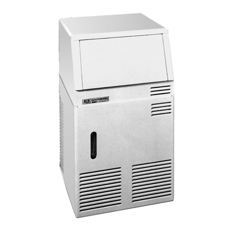
Icematic E Series User manual

Fabbricatori di ghiaccio serie E - Manuale service
Ice makers E series - Service manual
21 21 nano 25 35 35L 45 50 60 75 90 150

w
t
e
y
a
d
u
i
f
g
h
j
k
;
2)
2!
2@ 2#
2$
r
max 32°C
min 10°C
max 0,5 MPa (5 bar)
min 0,1 MPa (1 bar)
q
t
o
min
50 mm
s
ON/OFF CLEAN BUTTON

w
t
e
y
a
d
u
i
f
g
h
j
k
;
2)
2!
2@ 2#
2$
r
max 32°C
min 10°C
max 0,5 MPa (5 bar)
min 0,1 MPa (1 bar)
q
t
o
min
50 mm
s
ON/OFF CLEAN BUTTON
Italiano
3
71503816/0 - REV.0401/2013
INDICE
1. INSTALLAZIONE . . . . . . . . . . . . . . . . . . . . . . . . . . . . . . . . . . . . . . . . 4
1.1
COLLEGAMENTO DELL’APPARECCHIATURA
ALLA RETE ELETTRICA
. . . . . . . . . . . . . . . . . . . . . . . . . . . . . . 4
2. MESSA IN FUNZIONE . . . . . . . . . . . . . . . . . . . . . . . . . . . . . . . . . . . 5
3. FUNZIONAMENTO . . . . . . . . . . . . . . . . . . . . . . . . . . . . . . . . . . . . . 5
3.1 SEGNALI DI ALLARME PER I MOD. ARIA/ACQUA . . . 5
4. SEGNALAZIONE ELETTRONICA . . . . . . . . . . . . . . . . . . . . . . . . 6
5. ANOMALIE DI FUNZIONAMENTO . . . . . . . . . . . . . . . . . . . . . . 6
6. INFORMAZIONE PER IL SERVICE . . . . . . . . . . . . . . . . . . . . . . . 6
7. PULIZIA E MANUTENZIONE
7.1 PULIZIA DEL CONDENSATORE AD ARIA . . . . . . . . . . . 7
7.2 PULIZIA DEL FILTRO ENTRATA ACQUA . . . . . . . . . . . . . 7
7.3 PULIZIA DEL CONTENITORE . . . . . . . . . . . . . . . . . . . . . . . 7
7.4 CICLO DI LAVAGGIO E SANIFICAZIONE . . . . . . . . . . . . 7
7.5 COME ESEGUIRE IL CICLO DI LAVAGGIO
E SANIFICAZIONE . . . . . . . . . . . . . . . . . . . . . . . . . . . . . . . . . 7
8. DATI TECNICI PER IL SERVICE
8.1 FUNZIONE SCHEDA ELETTRONICA . . . . . . . . . . . . . . . . 8
8.2 INGRESSI E USCITE SCHEDA ELETTRONICA . . . . . . . . 8
8.3 CARATTERISTICHE DI FUNZIONAMENTO . . . . . . . . . . . . 8
8.4 CICLO DI LAVAGGIO . . . . . . . . . . . . . . . . . . . . . . . . . . . . . . . . 8
8.5 CARATTERISTICHE DELL’IMPIANTO FRIGORIFERO . . . 9
8.6 AVVISO DI MANUTENZIONE PROGRAMMATA . . . . . . . 9
8.7 CONNESSIONE DEI CAVI ELETTRICI E DEI
COMPONENTI ALLA SCHEDA ELETTRONICA . . . . . . . 10
8.8 KIT LAVAGGIO . . . . . . . . . . . . . . . . . . . . . . . . . . . . . . . . . . . . 10
9. RAEE . . . . . . . . . . . . . . . . . . . . . . . . . . . . . . . . . . . . . . . . . . . . . . . . . . . 35
10. SCHEMI ELETTRICI . . . . . . . . . . . . . . . . . . . . . . . . . . . . . . . . . . . . 36
Descrizione Pag.
ATTENZIONE
LE OPERAZIONI EVIDENZIATE CON
QUESTO SIMBOLO
SONO STRETTAMENTE RISERVATE
AL TECNICO PATENTATO.
In particolare:
• Allacciamenti elettrici
• Allacciamenti idrici
• Installazione della macchina
• Collaudo della macchina
• Interventi di riparazione su tutti i componenti
e organi della macchina
• Smontaggio della macchina
e/o suoi componenti
• Interventi di regolazione e taratura
• Manutenzione e pulizia della macchina
relativa a parti e componenti
- Elettrici
- Elettronici
- Meccanici
- Frigoriferi
IL TESTO EVIDENZIATO CON QUESTO SIMBOLO
È DI PARTICOLARE IMPORTANZA
O SEGNALA POTENZIALE PERICOLO
NOTA chiarisce le operazioni in corso
i
INFORMAZIONI GENERALI
• I produttori di ghiaccio con approvazione VDE portano sul-
l’imballaggio, sulla targhetta di immatricolazione e sulla car-
rozzeria il simbolo in fig. f.
CE
I nostri prodotti rientrano nelle direttive 2006/95/ec -
2004/108/ec pertanto riportano anche la marcatura sulla
copertina del libretto.
• Questo apparecchio non è inteso per uso di persone -inclusi
bambini- con ridotte capacità fisiche, sensoriali o mentali, o
senza esperienza e conoscenza, a meno che abbiano rice-
vuto istruzioni relativamente all’uso dell’apparecchio e siano
controllati da una persona responsabile per la loro sicurezza.
I bambini dovrebbero essere controllati in modo da assicu-
rare che non giochino con l’apparecchio
Non mettere in funzione l’apparecchio prima dell’inter-
vento del tecnico (fig. r).
46
44

Italiano
471503816/0 - REV.04 01/2013
1. INSTALLAZIONE
Prima di mettere in funzione il produttore di ghiaccio ese-
guire le seguenti operazioni:
1. Controllare che l’apparecchio non abbia subito danni du-
rante il trasporto (fig. q).
2. Estrarre dal deposito tutto il materiale in dotazione: tubo ali-
mentazione, tubo scarico, documentazione ed eventuali ac-
cessori.
3. Pulire l’interno del deposito con una spugna inumidita in
acqua tiepida unita ad un poco di bicarbonato di soda; sciac-
quare con acqua pura ed asciugare accuratamente.
4. Posizionare il produttore nella sede definitiva assicurandosi
che sia perfettamente in piano (fig. a).
Nota: nella scelta dell’ambiente in cui installare la macchina è
necessario assicurarsi che:
• la temperatura ambiente non scenda al di sotto dei 10°C (50°F)
e non superi i 43°C (110° F).
• la temperatura dell’acqua non sia inferiore a 10°C (50°F) e non
superi i 32°C (90°F) (fig. u).
• la pressione dell’acqua di alimentazione non sia inferiore a 0,1
MPa (1 bar) e non superi i 0,5 MPa (5 bar). Qualora la pres-
sione superi i 0,5 MPa prevedere l’applicazione di un riduttore di
pressione sull’alimentazione idrica alla macchina (fig. i).
• la macchina sia lontana da fonti di calore ed in posizione ben
aerata (fig. o).
Collegare solo alla rete d’acqua potabile.
5. Utilizzare il nuovo set di giunzioni mobili (tubo acqua) for-
nito con l’apparecchio. Il vecchio set di giunzioni non deve
essere riutilizzato.
6. Eseguire gli allacciamenti idrici prima di quelli elettrici.
7. Allacciare il tubo di alimentazione da 3/4” in dotazione, alla
macchina e alla linea idrica di alimentazione acqua fredda
potabile.
È consigliabile applicare per motivi di praticità e sicurezza un
rubinetto d’intercettazione, non di nostra fornitura (fig. h:
1. interruttore; 2. presa; 3. spina; 4. alimentazione idrica; 5. ru-
binetto; 6. scarico acqua dal condensatore: versione raffred-
damento ad acqua; 7. scarico acqua dal deposito; 8. scarico
acqua con sifone aperto).
8.
Applicare sul raccordo di scarico acqua della macchina il tubo
flessibile in dotazione del diametro interno di 20 mm. e di una
lunghezza adeguata (non superiore ad un metro dalla mac-
china) a raggiungere il pozzetto di scarico (fig.
h
).
Nota: Installare la macchina in posizione tale che la ventilazione
del gruppo frigorifero non sia in alcun modo ostacolata ( solo
per macchine raffreddate ad aria). (fig. s).
• Non installare la macchina in locali polverosi poiché si può veri-
ficare un rapido intasamento del condensatore del gruppo fri-
gorifero (solo per macchine raffreddate ad aria) (fig. 2))
• Nel caso in cui la macchina sia installata in zone dove l’acqua
potabile abbia un alto tenore di sali in soluzione, attenersi alle
istruzioni del costruttore onde limitare al minimo l’inconveniente.
•
Onde evitare che il ghiaccio assorba cattivi odori e sapori, non con-
servare mai nel contenitore alimenti, bottiglie ed altro.
• Durante il normale funzionamento non lasciare aperto lo spor-
tello del contenitore del ghiaccio
Nell’impianto elettrico deve essere presente un interruttore
differenziale (salvavita).
1.1 COLLEGAMENTO DELL’APPARECCHIATURA
ALLA RETE ELETTRICA
•Nei casi in cui il cavo di alimentazione elettrica dell’apparec-
chio risultasse danneggiato, esso dovrà essere sostituito da
personale qualificato in modo da prevenire qualsiasi rischio
alle persone
i
i
Italiano
5
71503816/0 - REV.0401/2013
2. MESSA IN FUNZIONE 3. FUNZIONAMENTO
1. prendere visione delle figure illustrative:
• togliere il coperchio previa rimozione delle viti di fissaggio
relative.
• sbloccare il motoriduttore, le palette ed il galleggiante (dove
presente) togliendo gli arresti 1, 2, 3, applicati in fabbrica per
evitare danni durante il trasporto (fig. j). Nelle versioni con
raffreddamento ad acqua collegare allo scarico anche il se-
condo raccordo che convoglia l’acqua proveniente dal con-
densatore.
Nota: Per un perfetto deflusso dell’acqua dall’apparecchio pre-
vedere una pendenza minima del 3% della tubazione control-
lando cha la stessa non subisca strozzature o sifonamenti. È
opportuno che la tubazione scarichi in un sifone aperto (fig. h).
2. Prima di collegare la macchina elettricamente, accertarsi che
il voltaggio di rete corrisponda a quello indicato sulla tar-
ghetta d’immatricolazione posta sullo schianale dell’appa-
recchio.
La massima tolleranza consentita sulla variazione di ten-
sione è di ± 10% del valore nominale.
• Prevedere un circuito di alimentazione elettrica alla mac-
china, con un proprio interruttore generale bipolare ed aper-
tura dei contatti di almeno 3 mm. e con un proprio fusibile o
protezione automatica ed una presa elettrica dotata di col-
legamento a terra.
• Il tutto dimensionato secondo l’amperaggio indicato sulla
targhetta d’immatricolazione (fig. ;). La presa elettrica
dovrà essere facilmente accessibile.
Per avviare e spegnere la macchina basta premere il pulsante
ON/OFF .
• I fabbricatori di ghiaccio in cubetti Icematic possono essere fa-
cilmente adattabili all’arredamento di ogni locale.
• La formazione del ghiaccio in cubetti avviene attorno ai pe-
duncoli dell’evaporatore, immersi in una vaschetta, riempita di
acqua agitata in continuazione da palette rotanti.
•
Il livello dell’acqua nella vaschetta è mantenuto costante da un gal-
leggiante collegato ad un micro che comanda l’apertura o meno di
una elettrovalvola di entrata acqua dell’alimentazione idrica.
• Quando i cubetti hanno raggiunto la dimensione prevista, essi
vengono a contatto con le palette agitatrici facendo oscillare il
motoriduttore relativo, il quale sollecita un micro che tramite un
relé provoca contemporaneamente:
- l’invio di gas caldo all’evaporatore mediante l’apertura di una
elettrovalvola, con conseguente graduale distacco dei cubetti
dai peduncoli dell’evaporatore.
- il ribaltamento della vaschetta acqua collegata mediante una
leva ad un motoriduttore.
• I cubetti una volta staccatisi scivolano su una griglia inclinata
posta all’interno della vaschetta e vengono convogliati nel sot-
tostante deposito.
• L’acqua residua della vaschetta viene raccolta nell’apposito re-
cipiente situato su un lato del deposito e convogliata verso lo
scarico. La vaschetta ritorna automaticamente dopo circa un mi-
nuto in posizione orizzontale e si riempie d’acqua fino al livello
prestabilito. Nel frattempo la valvola del gas caldo ritorna a chiu-
dersi ed il ciclo di formazione ghiaccio procede regolarmente; il
tempo per un ciclo completo può variare da circa 15’ a circa 25’
a seconda della temperatura dell’acqua e dell’ambiente.
• La quantità di ghiaccio nel deposito è controllata dalla sonda
elettronica fissata su una parete del deposito stesso; quando i
cubetti raggiungono il livello del bulbo la macchina si arresta
completamente. Dopo prelievi di ghiaccio che permettono di
liberare il bulbo dal contatto con i cubetti, il produttore ripren-
derà la sua normale produzione.
Nota: Dopo i prelievi liberare il bulbo di controllo da eventuali resi-
dui di ghiaccio per una più celere ripresa della produzione.
• Il pulsante CLEAN ha le seguenti funzioni:
1. Reset avviso manutenzione (vedi il par. 7.6)
2. Reset inizio ciclo lavaggio (vedi istruzioni)
3. Eseguire il ciclo di lavaggio e sanificazione (vedi il par. 6.5)
4. Per resettare il funzionamento della macchina premere il pul-
sante ON/OFF .
3.1 SEGNALI DI ALLARME PER I MODELLI ARIA/ACQUA
•
Sovratemperatura condensatore: la macchina riparte automatica-
mente una volta ripristinate le cause di allarme. Le cause possono es-
sere: filtro aria intasato, ventilatore difettoso, temperatura ambiente
troppo elevata, mancanza acqua (solo per versione ad acqua).
•Errore acqua: in caso di mancanza acqua di rete la macchina ri-
parte automaticamente dopo 60 minuti dall’allarme.
Nota: È possibile uscire dalla condizione di allarme previo disinse-
rimento/ inserimento dell’energia elettrica (Pulsante ON/OFF).
•Arresto macchina per deposito pieno: la sonda del deposito,
comandata dalla scheda elettronica, ferma la macchina quando
il ghiaccio viene a contatto. La macchina si arresta alla fine del
ciclo di sbrinamento.
i
i
i

Italiano
671503816/0 - REV.04 01/2013
6. INFORMAZIONI SERVICE
LL= lampeggio lento
LV= lampeggio veloce
LA= Lampeggio alternato
ON= Luce fissa
1. Controllare che il rubinetto della rete idrica di alimentazione
sia aperto, quindi inserire la spina di alimentazione elettrica
della macchina nella presa e accendere l’interruttore di linea
predisposto; la macchina inizia in funzionamento automa-
tico (fig. g) dopo aver premuto il pulsante ON/OFF di av-
viamento (fig. 2@).
2. Controllare che l’acqua arrivi alla vaschetta, che il sensore e/o
il galleggiante arresti l’entrata prima del trabocco e che non
esistano perdite nell’impianto e nei condotti idrici. Il normale
livello d’acqua all’interno della vaschetta è a circa 5./.10 mm.
dai bordi superiori. (fig. k)
La regolazione del livello acqua può avvenire ruotando il
micro galleggiante o il sensore acqua sull’apposita feritoia
prevista sul supporto relativo, previo allentamento della vite
di fissaggio 1 (fig. k). Tale regolazione deve avvenire con ali-
mentazione elettrica disinserita.
3. Verificare che non si producano vibrazioni anormali a causa
di viteria allentata.
4. Nel caso di necessità di intervento per perdite d’acqua, ser-
raggio viteria od altro, arrestare sempre prima il produttore.
5. Controllare un ciclo di produzione ghiaccio verificando che
i cubetti vengano scaricati nel deposito.
6. Verificare la funzionalità della sonda deposito: appoggiando
un cubetto di ghiaccio sul bulbo all’interno del contenitore
il produttore dovrebbe arrestarsi entro 1 minuto e ripartire
automaticamente dopo averlo tolto, in tempo poco supe-
riore.
7. Rimontare il coperchio tolto in precedenza.
LE SEGUENTI OPERAZIONI DEVONO
ESSERE EFFETTUATE ESCLUSIVAMENTE
DA UN INSTALLATORE PATENTATO
5.
ANOMALIE DI FUNZIONAMENTO
•In caso di sovratemperatura condensatore
La macchina si ferma e rimane in funzione solo la condensazione aria/acqua. La macchina riparte automaticamente quando la tem-
peratura ritorna al di sotto dei limiti stabiliti. Solo dopo il terzo allarme consecutivo nell’arco di 5 ore la macchina si arresta definiti-
vamente.
•Ciclo di congelamento troppo lungo
Nel caso di tre allarmi consecutivi nell’arco di 5 ore, la macchina si ferma.
Calcolo del tempo massimo del ciclo di congelamento:
1º ciclo = 50’
2º ciclo = durata del 1º ciclo x 1,5.
Se il 1º ciclo è durato meno di 7’ il tempo massimo del ciclo successivo sarà di 50’.
•Sbrinamento troppo lungo
Tempo di sbrinamento maggiore di 2 minuti e 2 errori consecutivi nell’arco di 5 ore, la macchina si ferma.
•Ciclo di congelamento minore di 7 minuti
L’elettronica calcola il tempo di ciclo troppo lungo uguale a 50 minuti.
•Carico acqua troppo lungo
Se il tempo di carico acqua è superiore a 5’ la macchina si ferma in allarme. Dopo una sosta di 120’ la macchina riparte automatica-
mente. Nel caso di mancanza acqua continuativa, la macchina compie dei tentativi di ripartenza ogni 120’.
4. SEGNALAZIONI
Funzione Stato Led 1
Verde
Led 2
Rosso Note
Macchina accesa ON OFF
Vale per tutti gli stati
che non siano di
allarme/errore
Errore sonda
temperatura
deposito
OFF LL
Sonda temperatura
“out of range”
Macchina spenta
Errore sonda
temperatura
condensatore
OFF LL
Sonda temperatura
“out of range”
La macchina continua a
funzionare
Errore ciclo freddo
troppo lungo
o sbrinamento
troppo lungo
ON ON Macchina spenta
Errore
sovratemperatura
condensatore
OFF ON Macchina spenta
Errore mancanza
acqua LL ON La segnalazione avviene
dopo i tentativi di riavvio
Avviso
manutenzione LA LA
Raggiunto numero ore di
funzionamento stabilito.
La macchina continua a
funzionare
Lavaggio / pulizia LV LV Segnala quando si è nella
routine di lavaggio
Attesa avvio LV OFF Attende di partire dopo lo
spegnimento
Italiano
7
71503816/0 - REV.0401/2013
7. PULIZIA E MANUTENZIONE
• Per la pulizia della carrozzeria, é sufficiente usare un panno
inumidito con un prodotto specifico, privo di cloro, per ac-
ciaio inossidabile.
Nota: Tutte le operazioni di pulizia e manutenzione devono es-
sere eseguite previo disinserimento dell’alimentazione elettrica
dell’apparecchio.
6.1 PULIZIA DEL CONDENSATORE AD ARIA
•Per valorizzare al meglio il vostro produttore in termini di resa
e durata è necessario effettuare ogni settimana la pulizia del
filtro aria posizionato nella parte frontale del produttore (vedi
fig. 2#).
•Per la rimozione del filtro è sufficiente estrarlo e lavarlo con
un getto di acqua tiepida e asciugarlo prima del rimontaggio.
Non utilizzare spazzole o oggetti contundenti per la pulizia
del filtro.
È assolutamente vietato far funzionare il produttore senza
il filtro dell’aria per evitare il malfunzionamento.
6.2 PULIZIA DEL FILTRO ENTRATA ACQUA
•Chiudere il rubinetto d’intercettazione d’acqua all’apparec-
chio, staccare il tubo entrata acqua e sfilare con una pinza la
retina filtrante situata sull’elettrovalvola entrata acqua.
•Pulire la retina con getto d’acqua e rimontarla nella propria
sede.
6.3 PULIZIA DEL CONTENITORE
•Estrarre il ghiaccio dal deposito. Pulire l’interno con una spu-
gna inumidita in acqua tiepida unita ad un poco di bicarbo-
nato di soda;
•sciacquare con acqua pura ed asciugare accuratamente.
6.4 Il CICLO DI LAVAGGIO E SANIFICAZIONE
•Per ovviare ai problemi dati dalla durezza dell’acqua di ali-
mentazione e quindi la formazione di impurità sulle parti e
componenti a contatto con l’acqua, la macchina e’ stata do-
tata di una funzione “Self Cleaning”. Tale funzione, grazie al-
l’azione pulente di un prodotto specifico, una bustina di
prodotto in polvere e la bottiglia dosatrice, permette di man-
tenere pulita e igienizzata la macchina dal calcare e dalle in-
crostazioni.
•Per garantite una buona pulizia del fabbricatore di ghiaccio
si consiglia di eseguire il ciclo di lavaggio almeno 3-4 volte al-
l’anno in funzione della durezza dell’acqua di alimentazione.
Kit lavaggio (optional)
Il kit è composto da una
bottiglia in plastica con
tubo in gomma, una confe
zione di acido citrico da 1
kg. e le istruzioni per il ciclo
di lavaggio.
6.5
COME ESEGUIRE IL CICLO DI LAVAGGIO E SANIFICAZIONE
Prendere le dovute precauzioni nel maneggiare l’acido ci-
trico mentre si prepara la soluzione
(acqua+acido citrico, vedi tabella) indos-
sando guanti e occhiali protettivi.
•Spegnere la macchina.
•Togliere tutto il ghiaccio dal contenitore.
•Servendosi del prodotto specifico e della
bottiglia in plastica, preparare la soluzione
sciogliendo la polvere in acqua tiepida (max.
40°C) secondo le quantità riportate nella ta-
bella allegata. Mescolare il tutto facendo at-
tenzione che non si verifichino dei grumi.
•Accendere la macchina, premendo il pul-
sante ON/OFF e tenendo contemporaneamente premuto
anche il pulsante di RESET (fig. 2@). Per premere il pulsante
di RESET utilizzare una spina di diametro adeguato al foro
sul quadro comandi.
•Entrambi i leds lampeggiano velocemente. Aprire lo spor-
tello del deposito, attendere che la bacinella ritorni in posi-
zione di chiusura. Introdurre la canula nella bottiglia in tutta
la sua lunghezza nell’apposito foro (fig. 2$) e scaricare tutta
la miscela precedentemente preparata, facendo pressione
con le mani sulla bottiglia. Chiudere lo sportello e ripremere
il pulsante RESET per avviare il ciclo di LAVAGGIO.
•Una volta avviato il ciclo di lavaggio il lampeggio dei leds sarà
più lento. Durante la funzione lavaggio provvedere a riscia-
quare abbondantemente il deposito.
•La durata del ciclo di lavaggio e di circa 3 ore.
•Una volta avviata la funzione anticalcare non è possibile in-
terrompere il ciclo di lavaggio. In caso di mancanza di ten-
sione, la macchina riprende da dove si era fermata.
•Al termine del ciclo di lavaggio e risciacquo la macchina ri-
parte in ciclo freddo.
Per tutti gli interventi di manutenzione straordinaria e/o
riparazione (parti meccaniche, frigorifere, elettriche) che
comportino la regolazione e/o sostituzione di componenti,
rivolgersi sempre a un centro servizi autorizzato.
Se l’apparecchio dovesse rimanere inutilizzato per lunghi
periodi:
- disattivare la macchina
- togliere tutto il ghiaccio dal contenitore
- scaricare tutta l’acqua
- eseguire un’accurata pulizia
- lasciare lo sportello del contenitore leggermente aperto.
•Dopo un lungo periodo di inattività si consiglia di eseguire
un ciclo di pulizia prima di iniziare la produzione di ghiaccio.
i
LE SEGUENTI OPERAZIONI DEVONO
ESSERE EFFETTUATE ESCLUSIVAMENTE
DA UN INSTALLATORE PATENTATO
Quantitativi di acido citrico da miscelare con acqua
nella bottiglia per ottenere la miscela
MODELLO Q.TÀ ACIDO CITRICO
E21 - E25 200 gr.
E35 - E35L 250 gr.
E45 - E50 500 gr.
E60 - E75 - E90 500 gr.

Italiano
871503816/0 - REV.04 01/2013
8. DATI TECNICI PER IL SERVICE
8.1 FUNZIONI SCHEDA ELETTRONICA
•controllo del livello del ghiaccio con sonda
•controllo della temperatura di condensazione con sonda
(stop macchina con temperatura > 70°C versione acqua; >
di 80°C aria).
•Controllo della manutenzione. Si può programmare l’avviso
della manutenzione dopo un numero di ore di funziona-
mento.
•Controllo del ciclo di lavaggio / pulizia da farsi periodica-
mente con comando manuale.
8.2 INGRESSI E USCITE DELLA SCHEDA ELETTRONICA
•Sonda Condensatore: con temperatura condensatore
< 24°C la scheda fa ciclare il ventilatore in modo da garantire
una condizione ottimale della condensazione e della resa
della macchina.
•Valori di resistenza delle sonde di temperatura (sonda depo-
sito e sonda condensatore) riferiti alla temperatura ambiente:
•RESET DELLA CHEDA MICROPROCESSORI
Premendo il pulsante ON/OFF .
8.3 CARATTERISTICHE DI FUNZIONAMENTO
•All’avviamento la macchina va in brinamento e scarica l’ac-
qua della bacinella.
•Il ciclo di produzione si avvia con due minuti di ritardo che
permettono un corretto bilanciamento dell’impianto frigori-
fero e quindi un miglior rendimento e una migliore produ-
zione.
•Durante il funzionamento della macchina, al termine di ogni
sbrinamento, il carico acqua avviene con 80 secondi di ri-
tardo, per permettere il sottoraffreddamento dell’evapora-
tore.
•Quando il deposito è pieno di ghiaccio, la sonda viene a con-
tatto con i cubetti e la scheda elettronica arresta la macchina
solo al termine del ciclo di sbrinamento. Questo per avere
sempre dei cubetti completamente formati e delle stesse di-
mensioni.
•Segnalazione di allarme per i modelli versione aria/acqua:
- surriscaldamento del condensatore: la macchina va in al-
larme e riparte automaticamente una volta che la causa è
stata rimossa e/o la temperatura è rientrata nel range di fun-
zionamento stabilito;
- errore di mancanza acqua di alimentazione: in caso di man-
canza acqua di alimentazione la macchina riparte automati-
camente dopo 60 minuti dal ripristino dell’allarme.
8.4 CICLO DI LAVAGGIO
Nota: Una volta avviata la macchina, non è possibile uscire dal
ciclo di lavaggio anche se si spegne e riaccende il produttore poi-
ché l’elettronica mantiene in memoria il ciclo.
•Tempo di un ciclo completo di lavaggio: 3 ore
•Il ciclo di lavaggio è formato da: 90 minuti di lavaggio più 5
risciaqui di 15 minuti ciascuno.
•Al termine del ciclo di lavaggio la macchina riparte automa-
ticamente in ciclo freddo.
•Il sensore livello acqua nella bacinella lavora in presenza di
acque con conducibilità compresa tra i 20 e i 1000 micro-sie-
mens per centimetro.
•Il sensore di livello acqua può essere sostituito da un micro
galleggiante. L’attacco è uguale per entrambi.
•Nel caso la macchina sia alimentata con acqua addolcita (de-
mineralizzata) si consiglia di installare il kit galleggiante (fig.
k).
In caso di errato avvio del ciclo (da parte dell’utente) per
uscire dal ciclo bisogna premere per più di 10 secondi il pul-
sante di reset durante il lavaggio. (Non attivo durante i ri-
sciaqui).
i
QUESTE OPERAZIONI DEVONO ESSERE
EFFETTUATE ESCLUSIVAMENTE
DA UN INSTALLATORE PATENTATO
Temperatura °C Resistenza sensore Ohm
20 2762,034556
25 2200,000000
30 1765,531939
Ingressi in
bassa tensione
Sonda condensatore
Sonda deposito
Sensore livello acqua
Micro Inizio sbrinamento
Micro ne sbrinamento
Ingressi in tensione
230V/ 50HZ
Compressore
Motore di ribaltamento
Elettrovalvola gas caldo
Elettrovalvola acqua
Motoriduttore palette
elettroventilatore
Scheda Elettronica
Italiano
9
71503816/0 - REV.0401/2013
8.5 CARATTERISTICHE DELL’IMPIANTO FRIGORIFERO GAS
FREON R134a
•Medio e massimo assorbimento elettrico macchine a palette
serie “E” a temperatura ambiente di 32°C.
•Pressione di condensazione e temperatura di evaporazione
a inizio e fine ciclo a temperatura ambiente di 32°C.
* Espresso in litri d’acqua per ora a temperatura acqua di
15°C e ambiente di 21°C
8.6 AVVISO DI MANUTENZIONE PROGRAMMATA.
•Il tempo di manutenzione programmata viene settato in fab
brica a 0 ore.
•Per modificare questo tempo e/o azzerare la funzione di ri
chiamo manutenzione, procedere al settaggio dei dip
switch come da tabella allegata.
* Nel caso di manutenzione programmata, per resettare e ri
pristinare la programmazione al valore iniziale premere il
pulsante RESET per almeno 5 secondi.
Macchina
Tipo di gas
Assorbimento Max.
Ampere
Assorbimento
Medio Ampere
Pressione Di
Condensazione
All’avviamento (Bar)
Temperatura Di
Evaporazione
All’avviamento
(°c)
Pressione Di
Condensazione
Fine Ciclo (Bar)
Temperatura Di
Evaporazione
Fine Ciclo
(°c)
Consumo Elettrico
24 Hrs/Kw
Cubetti per ciclo e
peso di un cubetto
Consumo Acqua l/h*
E21 R134a 2 A 1,8 A 11,5 -3,3 9 -17 7,5 15/17 GR 6
E25 R134a 1,6 A 1,4 A 11,0 -2 9 -13 5,8 15/17 GR 2,8
E35 R134a 2,7 A 2,1 A 14,0 -2 10 -15 8,6 20/17 GR 4,7
E60 R134a 4,2 A 3,4 A 14,7 -2 11,3 -15 12,7 35/17 GR 7,5
E75 R134a 4,6 A 3,8 A 14,6 -2 11,4 -13 13,3 60/17 GR 9,4
E90 R134a 4,7 A 4,2 A 14,9 -2 10,8 -15 14,4 60/17 GR 12,5
DIP NOTE
1 2
1OFF Intervallo di manutenzione a 0 ore
ON
2OFF Intervallo di manutenzione a 2000 ore
ON
3OFF Intervallo di manutenzione a 6000 ore
ON
4OFF Intervallo di manutenzione a 3500 ore
ON

Italiano
10 71503816/0 - REV.04 01/2013
8.7 CONNESSIONE DEI CAVI ELETTRICI E DEI COMPO
NENTI ALLA SCHEDA ELETTRONICA
Rispettare le connessioni con i colori dei cavi elettrici.
8.8 KIT LAVAGGIO
•Il kit è composto da una bottiglia in plastica con tubo in
gomma, una confezione di acido citrico da 1 kg. e le istru
zioni per il ciclo di lavaggio.
Sensore livello galleggiante
Micro ribaltamento
Cumune micro
Micro sbrinamento
Sonda deposito ghiaccio
Sonda condensatore
Azzurro
Marrone
Arancio
Nero
Bianco
Rosso
Dip. Switch
per set ore
manutenzione
English
11
71503816/0 - REV.0401/2013
INDICE
1. INSTALLATION . . . . . . . . . . . . . . . . . . . . . . . . . . . . . . . . . . . . . . . . 12
1.1
CONNECTING THE APPLIANCE TO THE MAINS
. . . . . . 12
2. ACTIVATING THE MACHINE . . . . . . . . . . . . . . . . . . . . . . . . . . . 13
3. OPERATION . . . . . . . . . . . . . . . . . . . . . . . . . . . . . . . . . . . . . . . . . . . 13
3.1 ALARM SIGNALS FOR AIR / WATER MODELS . . . . . 13
4. CONTROL PANEL SIGNALS . . . . . . . . . . . . . . . . . . . . . . . . . . . 14
5. OPERATING PROBLEMS . . . . . . . . . . . . . . . . . . . . . . . . . . . . . . . 14
6. SERVICE INFORMATION . . . . . . . . . . . . . . . . . . . . . . . . . . . . . . . 14
7. CLEANING AND MAINTENANCE
7.1 CLEANING THE AIR CONDENSER . . . . . . . . . . . . . . . . . 15
7.2 CLEANING THE WATER INLET FILTER . . . . . . . . . . . . . . 15
7.3 CLEANING THE CONTAINER . . . . . . . . . . . . . . . . . . . . . . 15
7.4 THE WASH AND SANITATION CYCLE . . . . . . . . . . . . . . 15
6.5 IMPLEMENTING THE WASH
AND SANITATION CYCLE . . . . . . . . . . . . . . . . . . . . . . . . . 15
8. TECHNICAL SERVICE DATA
8.1 ELECTRONIC BOARD FUNCTIONS . . . . . . . . . . . . . . . . 16
8.2 ELECTRONIC BOARD INPUTS AND OUTPUTS . . . . . 16
8.3 OPERATION CHARACTERISTICS . . . . . . . . . . . . . . . . . . . . 16
8.4 WASHING CYCLE . . . . . . . . . . . . . . . . . . . . . . . . . . . . . . . . . 16
8.5 FEATURES OF THE GAS REFRIGERATOR
PLANT FREON R404a . . . . . . . . . . . . . . . . . . . . . . . . . . . . . . 17
8.6 PROGRAMMED MAINTENANCE WARNING . . . . . . . . . 17
8.7 CONNECTION OF ELECTRICAL CABLES AND
COMPONENTS TO THE PC BOARD . . . . . . . . . . . . . . . . . 18
8.8 CLEANING KIT . . . . . . . . . . . . . . . . . . . . . . . . . . . . . . . . . . . . 18
9. WEE . . . . . . . . . . . . . . . . . . . . . . . . . . . . . . . . . . . . . . . . . . . . . . . . . . . 35
10. WIRING DIAGRAM . . . . . . . . . . . . . . . . . . . . . . . . . . . . . . . . . . . . . 36
Description Pag.
WARNING
THE FOLLOWING OPERATIONS AND THOSE
HIGHLIGHTED BY THE SYMBOL AT THE SIDE
ARE STRICTLY FORBIDDEN FOR WHOEVER USES
THE MACHINE SUCH OPERATIONS MUST BE
PERFORMED EXCLUSIVELY BY QUALIFIED PERSONNEL
Especially:
• electrical connections
• water connections
• machine installation
• machine testing
• repairing machine components and parts
• disassembling the machine and/or its
components
• adjustments and settings
• machine cleaning and maintenance relative to
the following parts and components:
- electrical
- electronic
- mechanical
- cooling
THE TEXT WITH THIS SYMBOL
IS OF MORE IMPORTANTE
OR POTENTIAL DANGER SIGNALS
NOTE claries the ongoing operations
i
GENERAL INFORMATION
• The ice making machines approved by VDE bear the symbol
shown in fig. fon the packing, the serial number plate and
the machine structure.
CE
Our products comply with directives 2006/95/ec
2004/108/ec therefore they also bear the marking on the man-
ual cover.
• This appliance is not intended to be used by persons - in-
cluding children - with reduced physical, sensory or mental
capabilities, or with no experience and knowledge, unless
they have been instructed on how to use the appliance and
are supervised by a person who is responsible for their safety.
Children should be supervised to ensure that they do not
play with the appliance
Do not start the appliance before the technician intervenes
(fig. r).
46
44

English
12 71503816/0 - REV.04 01/2013
1. INSTALLATION
Implement the following operations before activating the
ice maker:
1. Verify that the ice maker has not been damaged during
transport (fig. q).
2. Remove all the material provided from the container: supply
pipe, drain pipe, documentation and any accessories.
3. Clean inside the container with a sponge dampened with
warm water and a little sodium bicarbonate; rinse with clean
water and dry carefully.
4. Place the ice maker in its definite location and ensure that it
is perfectly level (fig. a).
Note: When choosing where to install the appliance, make sure
that:
• the room temperature never drops below 10°C (50°F) and does
not exceed 43°C (110° F).
• the water temperature must be no less than 10°C (50°F) and no
more than 32°C (90°F) (fig. u).
• the supply water pressure must be no less than 0,1 MPa (1 bar)
and no more than 0,5 MPa (5 bar).
Should the pressure exceed 0,5 MPa, install a pressure reducer on
the machine water supply (fig. i).
• d) the machine is away from heat sources and in a well-venti-
lated area (fig. o).
Connect only to the drinking water mains
5. Use the new set of mobile junctions (water pipe) supplied
with the appliance. The old set of junctions must not be
reused.
6. Install the water connections before the electrical connec-
tions.
7. Connect the 3/4’’ supply pipe (supplied) to the machine and
to the cold drinking water supply line.
For practical and safety purposes, it is advisable to install a
shut-off valve (not supplied by CastelMac) (fig. h: 1. switch;
2. socket; 3. electrical plug; 4. water supply; 5. valve; 6. water
drain from the condenser: water-cooled version; 7. water
drain from the container; 8. water drain with open siphon).
8. Apply the flexible pipe (supplied) with a 20 mm inner diam-
eter and of adequate length (not more than 1 metre from
the machine) to the water drain fitting of the machine in
order to reach the drain well (fig. h).
Note: Install the machine in a position that the ventilation of the
cooling unit is not obstructed in any way (only for air-cooled ma-
chines) (fig. s).
• Do not install the machine in a dusty room as the condenser of
the cooling unit can be easily clogged (only for air-cooled ma-
chines) (fig. 2)).
• If the machine is installed in an area where the drinking water
has a high content of salt solutions, follow the manufacturer's
instructions in order to minimise the problem.
• To prevent the ice from absorbing bad smells and tastes, never
store food, bottles, etc. in the container.
• Do not leave the ice container door open during normal opera-
tion.
There must be a differential switch (cut-out) in the electri-
cal system.
1.1. CONNECTING THE APPLIANCE TO THE MAINS
•If the power supply cable is damaged, it must be replaced
by qualified personnel to prevent any hazards to persons
i
i
English
13
71503816/0 - REV.0401/2013
2. ActIvAtING tHE MAcHINE 3. OpERAtION
Implement the following operations before activating the
ice maker.
1. look at the pictures:
• remove the cover by loosening the relative fastening screws.
• release the gear motor, the blades and the float (where ap-
plicable) by removing the factory-set stops 1, 2 and 3, which
have been fixed to prevent damage during transport (fig.
j). For the water-cooled models connect also the second
fitting to the water outlet, which conveys the water coming
from the condenser.
Note: Implement a minimum inclination of 3% to the pipes for
perfect water flow from the appliance, ensuring that these have
no narrowing sections and are not siphoned. It is advisable that
the pipes drain into an open siphon (fig. h).
2. Connect the machine to the power supply after having ver-
ified that the mains voltage corresponds to that on the serial
number plate on the rear panel of the appliance.
The maximum voltage variation tolerance allowed is ±
10% of the rated value.
• Provide a power supply circuit to the machine, with its own
bipolar main switch and a minimum of 3 mm contact open-
ing. The machine should also have its own fuse or automatic
protection and an earthed plug.
• All must be sized according to the amperage indicated on
the serial number plate (fig. ;). The socket must be easily
accessible.
Simply press the ON/OFF button to start and stop the
machine.
• The Icematic ice cube makers can be easily adapted to the
furnishing of every room.
• The ice cubes are formed around the fingers of the evapora-
tor, inside a tray filled with water and continuously moved
by revolving blades.
• The level of the water in the tray is kept constant by a float
connected to a microswitch that controls the opening and
closing of a water inlet electrovalve of the water supply.
• When the ice cubes reach the required dimensions, they
come in contact with the revolving blades that cause the rel-
ative gear motor to swing, which stresses a micro switch and
simultaneously causes the following through a relay:
- the delivery of hot gas to the evaporator by an electrovalve
opening, which leads to the cubes gradually dropping off
the fingers of the evaporator.
- the tilting of the water tray connected by means of a lever
to a gear motor.
• The cubes drop and slide on a slanting grid inside the tray
and are conveyed into the container beneath.
• The remaining water in the tray is collected into the relative
pan on one side of the container and conveyed towards the
drain. The tray automatically returns to its horizontal position
after about a minute and fills with water till the pre-set level.
In the meantime, the hot gas valve closes and the ice form-
ing cycle proceeds smoothly; a complete cycle can vary from
about 15’ to about 25’ depending on the water and room
temperatures.
• The quantity of ice inside the container is controlled by the
electronic sensor fixed on one side of the container itself;
when the ice cubes reach the level of the bulb, the machine
stops completely. After removing enough ice from the con-
tainer for no cubes to be in contact with the bulb, the appli-
ance will resume its normal production.
Note: After removing the ice cubes, remove any remaining ice
on the control bulb for production to resume quicker.
• The CLEAN button has the following functions:
1. Reset maintenance alert (see par. 7.6)
2. Reset the start of the wash cycle (refer to instructions)
3. Performs the cleaning and sanitation cycle (see par. 6.5)
4.
To reset machine operation, press the ON/OFF button
.
3.1 ALARM SIGNALS FOR AIR / WATER MODELS
•Overheating condenser: the machine restarts automatically
once the alarm has been resolved. The cause may be due to:
clogged air filter, faulty fan, room temperature too high, no
water (only in the water version).
•Water error: if there is no water, the machine restarts auto-
matically 60 minutes after the alarm is triggered.
Note: You can exit from the alarm status after having discon-
nected / connected the power supply (ON/OFF button).
•The machine stops when the container is full: the sensor
of the container is controlled by the control board and stops
the machine when the ice comes in contact with it. The ma-
chine stops at the end of the defrosting cycle.
i
i
i

English
14 71503816/0 - REV.04 01/2013
6. SERVICE INFORMATION
LL= flashing slowly
LV= flashing quickly
LA= alternate flashing
ON = steady light
1. Verify that the water supply valve is open, then plug in the
machine and switch on the main switch; the appliance starts-
up in automatic mode (fig. g) after having pressed the
ON/OFF start button (fig. 2@).
2. Verify that the water reaches the tray, the float stops the
water before the overflow and that there are no leaks in the
system and in the water channels. The normal level of water
inside the tray is about 5/10 mm from the upper edge (fig.
k).
The level of water can be adjusted by rotating the microfloat
or the water sensor on the slot on the relative support after
having loosened fastening screw 1 (fig. k). This adjustment
must be implemented after having disconnected the power
supply.
3. Verify that there is no abnormal vibration due to loose screws.
4.
Always stop the appliance before implementing any operations
to resolve water leaks, tighten screws, etc.
5. Verify an ice production cycle ensuring that the cubes are
conveyed into the container.
6. Verify that the container sensor functions properly: place an
ice cube on the bulb inside the container; the appliance
should stop within 1 minute and restart automatically shortly
after removing it.
7. Replace the cover previously removed.
THE FOLLOWING OPERATIONS MUST BE
IMPLEMENTED SOLELY BY OUR
QUALIFIED PERSONNEL
4. SIGNALS
5.
OPERATING PROBLEMS
•If the condenser overheats
The machine stops and only the air/water condensation remains in operation. The machine automatically restarts when the tem-
perature returns to below the limits set. Only after three consecutive alarms within a period of 5 hours, the machine turns off and
stays off.
•Freezing cycle too long
In the case of three consecutive alarms within 5 hours, the machine stops.
Calculation of the maximum time of the freezing cycle:
1st cycle = 50'
2nd cycle = duration of 1 cycle x 1.5.
If the 1st cycle lasted less than 7' the maximum time of the next cycle will be 50'.
•Defrosting too long
If the defrosting time is greater than 2 minutes and there are 2 consecutive failures within 5 hours, the machine stops.
•Freezing cycle less than 7 minutes
The electronics calculate the cycle time as too long at 50 minutes.
•Water loading too long
If the load time for the water is greater than 5' the machine stops in alarm. After a break of 120' the machine restarts automatically.
If water shortage is ongoing, the machine will attempt to restart every 120'.
Function Status Led 1
Green
Led 2
Red Notes
Machine ON ON OFF
Applicable to all
conditions that are
not in alarm/error
Bin temperature
sensor error OFF LL
Temperature sensor
out of range.
Machine OFF
Condenser
temperature
sensor error
OFF LL
Temperature sensor
out of range.
The machine
continuous to run
Error cold cycle too
long or defrosting
too long
ON ON Machine OFF
Condenser
overheating error OFF ON Machine OFF
No water error LL ON The signal is triggered
after attempting to restart
Maintenance
warning LA LA
The pre-set number of
operating hours has been
reached. The machines
continous to run
Wash / clean LV LV Signalled during the wash
routine
Start stand-by LV OFF Waits to start after
switch-o
English
15
71503816/0 - REV.0401/2013
7. CLEANING AND MAINTENANCE
• Use a cloth dampened with a specific chlorine-free product
for stainless steel to clean the structure.
Note: Disconnect the electrical power supply from the appliance
to perform maintenance and cleaning operations.
6.1 CLEANING THE AIR CONDENSER
•To make the most of your appliance in terms of efficiency
and durability, the air filter at the front of the machine must
be cleaned every week (fig. 2#).
•The filter is removed by simply extracting it. Simply wash the
filter with a water jet of warm water and dry it before setting
it back in place.
Do not use brushes or blunt objects to clean the filter.
It is absolutely forbidden to operate the producer without
the air filter to prevent malfunctioning.
6.2 CLEANING THE WATER INLET FILTER
•Close the water shut-off valve of the appliance, disconnect
the water inlet pipe and remove the filter screen that is on
the water inlet electrovalve with a pair of pliers.
•Clean the screen with a water jet and reassemble it into its
place.
6.3 CLEANING THE CONTAINER
•Remove the ice from the container. Clean inside the con-
tainer with a sponge dampened with warm water and a lit-
tle sodium bicarbonate;
•rinse with clean water and dry carefully.
6.4 THE WASH AND SANITATION CYCLE
•The machine has been equipped with a “Self Cleaning” func-
tion in order to remedy the problems deriving from the hard-
ness of the supply water and therefore, the formation of
impurities on the components and parts that are in contact
with the water.
Thanks to the cleaning action of a specific product, which
comes in the form of powder in a sachet and a dosing bot-
tle, this function keeps the machine clean and sanitised from
limescale and deposits.
•To guarantee proper cleaning of the ice maker one recom-
mends carrying out the wash cycle at least 3-4 times a year,
according to the hardness of the water supply.
Cleaning kit (optional)
The kit is composed of a plas
tic bottle with rubber pipe,
one confection of acid citric 1
kg., and instructions for the
cleaning procedure.
6.5 IMPLEMENTING THE WASH AND SANITATION CYCLE
Adopt proper precautions when handling citric acid whilst
preparing the solution (water+ citric acid,
see the table). Wear protective gloves and
goggles.
•Turn the machine off.
•Remove all ice from the container.
•Using the specific product and the plastic
bottle, prepare the solution by dissolving
the powder in warm water (max. 40°C), ac-
cording to the quantities shown on the at-
tached table. Mix well whilst ensuring that
no lumps are formed.
•Switch the machine on by pressing the
ON/OFF button whilst keeping the RESET button pressed
(fig. 2@). Press the RESET button using a pin of suitable di-
ameter to enter the appropriate hole.
•Both LEDs will flash quickly. Open the deposit hatch, wait for
the tray to go back into closing position. Insert the cannula
into the bottle throughout its length in the appropriate hole
(fig. 2$) and drain all the previously prepared descaling mix-
ture, applying pressure with your hands on the bottle. Close
the hatch and repress the RESET button to start the WASH-
ING cycle.
•Once the wash cycle is started, LED flashing will slow down.
During the wash function, rinse the container thoroughly.
•The duration of the washing cycle is of approximately 3
hours.
•Once the descaling function has started it is not possible to
interrupt the washing cycle. In case of a power-cut, the ma-
chine resumes from where it had stopped.
•At the end of the washing and rinsing cycle the machine
restarts in the cold cycle.
For all extraordinary maintenance and/or repairs (me-
chanical, cooling and electrical parts) that require adjust-
ments and/or components to be replaced, always refer to
an authorised service centre.
If the appliance should not be used for long periods of
time:
- disable the machine
- remove all the ice from the container
- drain all the water
- thoroughly clean the machine
- leave the door of the container ajar
•After a long period of inactivity one recommends to perform
a cleaning/descaling cycle before commencing ice produc-
tion.
i
THE FOLLOWING OPERATIONS MUST BE
IMPLEMENTED SOLELY BY OUR
QUALIFIED PERSONNEL
Quantities of citric acid to be mixed with water
in the bottle to obtain the mixture
MODEL CITRIC ACID Q.TY
E21 - E25 200 gr.
E35 - E35L 250 gr.
E45 - E50 500 gr.
E60 - E75 - E90 500 gr.
English
16 71503816/0 - REV.04 01/2013
8. TECHNICAL SERVICE DATA
8.1 ELECTRONIC BOARD FUNCTIONS
•Ice level check with probe
•Condensing temperature check with probe (machine stop
with temperature > 70°C water version; > of 80°C air).
•Maintenance check. The maintenance alert can be pro-
grammed after a certain number of hours of functioning.
•Wash/cleaning cycle check to be carried out periodically with
manual control.
8.2 ELECTRONIC BOARD INPUTS AND OUTPUTS
•Condenser probe: with condenser temperature < 24°C, the
board makes the fan turn guaranteeing optimal condition of
condensation and machine yield.
•Resistance values of the temperature probes (deposit probe
and condenser probe) with reference to the room tempera-
ture:
•PCB MICROPROCESSOR RESET
Pressing the ON/OFF button.
8.3 OPERATION CHARACTERISTICS
•On the starting the machine goes into defrosting and dis-
charge the water pan.
•The production cycle start with two minutes of delay that
allow a correct balancing of the refrigeration system and
therefore a good output and a best production.
•During the machine operation, at the end of every defrost-
ing, the water load happens with 80 seconds of delay, this to
allow the evaporator subcooling.
•When the bin is full of ice, the probe comes in contact with
the ice and the electronic card stop the machine only on the
end of defrosting time. This to always have the cubes com-
pletely formed and at the same dimensions.
•Signalling of alarms for the models air and water version:
- condenser overheating : the machine goes to alarm and it
restart again automatically once that the cause has been re-
moved and / or the temperature has re-entered in the range
of established operation;
- error of not water feeding: in case of lack of water the ma-
chine automatically start again after 60 minutes from the
alarm reset.
8.4 WASHING CYCLE
Note:
•Time of complete washing cycle: 3 hours
•The washing / cleaning cycle is formed of: 90 minutes of
washing plus 5 rinsing of 15 minutes each.
•At the end of the washing cycle the machine automatically
start again in cold cycle.
•The water level sensor inside the basin works with waters
with conductivity between 20 and 1000 micro-siemens per
centimetre.
•The water level sensor can be replaced by a microoat. Con-
nection is the same for both.
•If the machine is supplied with softened water (deminer-
alised), oat kit installation is recommended (g. k)
In case of incorrect startup cycle (by the user) to exit the
cycle you must press the reset button for more than 10 se-
conds during the wash. (Not active during rinse cycle).
i
THE FOLLOWING OPERATIONS MUST BE
IMPLEMENTED SOLELY BY OUR
QUALIFIED PERSONNEL
Temperature °C Sensor resistance Ohm
20 2762,034556
25 2200,000000
30 1765,531939
Low voltage
inputs
Condenser probe
Container Probe
Water level sensor
Defrosting start micro
Defrosting end micro
High voltage
inputs 230V/50HZ
Compressor
Tilting Motor
Hot gas electrovalve
Water electrovalve
Blades gear motor
Electric fan
Electronic board
English
17
71503816/0 - REV.0401/2013
8.5 FEATURES OF THE GAS REFRIGERATOR PLANT
FREON R134a
•Medium and maximum series “E” blade machines absorption
at room temperature of 32°C.
•Condensing pressure and evaporator temperature cycle start
and end at room temperature of 32°C.
* Expressed in water litres per hour at water temperature of
15°C and room temperature of 21°C
8.6 PROGRAMMED MAINTENANCE WARNING
•The programmed maintenance time is set at 0 hour by the
manufacturer.
•In order to modify this time and/or reset the maintenance
recall function; proceed with dipswitch setup, as shown in
the attached table.
* In case of programmed maintenance, to reset and to restore
the programming to the initial value it's necessary to press
the RESET button for at least 5 seconds.
DIP NOTE
1 2
1OFF Interval of maintenance to 0 hour
ON
2OFF Interval of maintenance to 2000 hours
ON
3OFF Interval of maintenance to 6000 hours
ON
4OFF Interval of maintenance to 3500 hours
ON
Machine
Gas
Max. ampere
Medium ampere
Condensing
pressure strarting
cycle (bar)
Evaporation
temperature
starting cycle (°c)
Condensing
pressure end cycle
(bar)
Evaporation
temperature end
cycle (bar)
Electrical
consumption
on 24 hrs/kw
Cubes for cycles and
weight singel cube
in gr
Water consumption
l/h*
E21 134 A 2 A 1,8 A 11,5 -3,3 9 -17 7,5 15/17 GR 6
E25 134 A 1,6 A 1,4 A 11 -2 9 -13 5,8 15/17 GR 2,8
E35 134 A 2,7 A 2,1 A 14 -2 10 -15 8,6 20/17 GR 4,7
E60 R134a 4,2 A 3,4 A 14,7 -2 11,3 -15 12,7 35/17 GR 7,5
E75 R134a 4,6 A 3,8 A 14,6 -2 11,4 -13 13,3 60/17 GR 9,4
E90 R134a 4,7 A 4,2 A 14,9 -2 10,8 -15 14,4 60/17 GR 12,5

English
18 71503816/0 - REV.04 01/2013
8.7 CONNECTION OF ELECTRICAL CABLES AND COMPONENTS
TO THE PC BOARD
Observe the connection with the colors of electric cables.
8.8 CLEANING KIT
•The kit is composed of a plastic bottle with rubber pipe, one con
fection of acid citric 1 kg., and instructions for the cleaning proce
dure.
Float level sensor
Micro tip
Cumun micro
Micro defrost
Probe deposit ice
Condenser probe
Blue
Brown
Orange
Black
White
Red
Dip. Switch
to set the
maintenance hours
Français
19
71503816/0 - REV.0401/2013
INDEX
1. INSTALLATION . . . . . . . . . . . . . . . . . . . . . . . . . . . . . . . . . . . . . . . . 20
1.1
BRANCHEMENT DE L’APPAREIL AU
RESEAU ELECTRIQUE
. . . . . . . . . . . . . . . . . . . . . . . . . . . . . . 20
2. MISE EN MARCHE . . . . . . . . . . . . . . . . . . . . . . . . . . . . . . . . . . . . . 21
3. FONCTIONNEMENT . . . . . . . . . . . . . . . . . . . . . . . . . . . . . . . . . . . 21
3.1 SIGNAL D’ALARME POUR LES MODELE
EN VERSION AIR / EAU . . . . . . . . . . . . . . . . . . . . . . . . . . . .21
4. SIGNALISATION TABLEAU DE COMMANDE . . . . . . . . . 22
5. ANOMALIES DE FONCTIONNEMENT . . . . . . . . . . . . . . . . . 22
6. INFORMATIONS POUR LE “SERVICE” . . . . . . . . . . . . . . . . . . 22
7. NETTOYAGE ET ENTRETIEN
7.1 NETTOYAGE DU CONDENSEUR A AIR . . . . . . . . . . . . 23
7.2 NETTOYAGE DU FILTRE D’ENTREE D’EAU . . . . . . . . . 23
7.3 NETTOYAGE DE LA RESERVE . . . . . . . . . . . . . . . . . . . . . 23
7.4 LE CYCLE DE LAVAGE ET DE DESINFECTION . . . . . . 23
7.5 COMMENT EFFECTUER LE CYCLE
DE LAVAGE ET DE DESINFECTION . . . . . . . . . . . . . . . . 23
8. DONNEES TECHNIQUE POUR LE SERVICE
8.1 FONCTIONS DE LA CARTE ELECTRONIQUE . . . . . . . 24
8.2 ENTREES ET SORTIES DE LA CARTE ELECTR. . . . . . . 24
8.3 CARACTERISTIQUES DE FONCTIONNEMENT . . . . . . . 24
8.4 CYCLE DE LAVAGE . . . . . . . . . . . . . . . . . . . . . . . . . . . . . . . . 24
8.5 CARACTERISTIQUES DE L'INSTALLATION
FROGORIFIQUE AU GAZ FREON R404A . . . . . . . . . . . 25
8.6 AVVERTISSEMENT D’ENTRETIEN PROGRAMME . . . 25
8.7 CONNEXION DES CÂBLES ÉLECTRIQUES ET
COMPOSANTS SUR LA CARTE PC . . . . . . . . . . . . . . . . 26
8.8 KIT NETTOYAGE . . . . . . . . . . . . . . . . . . . . . . . . . . . . . . . . . . 26
9. DEEE . . . . . . . . . . . . . . . . . . . . . . . . . . . . . . . . . . . . . . . . . . . . . . . . . . . 35
10. SCHEMAS ELECTRIQUES . . . . . . . . . . . . . . . . . . . . . . . . . . . . . . 36
Description Pag.
ATTENTION
LES OPÉRATIONS MARQUÉES PAR
CE SYMBOLE
EST STRICTEMENT CONFIDENTIELLE PAR
LE TECHNICIEN AGRÉÉ.
En particulier:
• raccordements electriques
• raccordements a l’alimentation d’eau
• installation de l’appareil
• essai de la machine
• interventions de reparation de tous composants
et organes de la machine
• demontage de la machine et/ou de ses
composants
• interventions de reglage et calibrage
• entretien et nettoyage des composants:
- electriques,
- electroniques,
- mecaniques,
- frigorifiques.
LE TEXTE DE CE SYMBOLE
REVÊT UNE IMPORTANCE PARTICULIÈRE
OU DES SIGNAUX DE DANGER POTENTIEL
NOTE clarie les opérations en cours
i
INFORMATIONS GENERALES
• Les producteurs de glace ont reçu l’approbation VDE dont
les symboles, représentés sur la fig. f, sont appliqués sur
l’emballage, la plaque d’immatriculation et la carrosserie.
CE
nos produits sont conformes aux directives 2006/95/ce
- 2004/108/ce et beneficient du marquage ce reporte sur
la couverture du manuel.
• Cet appareil ne peut être utilisé par des personnes -enfants
compris- ayant des capacités physiques, sensorielles ou men-
tales réduites ou sans expérience ni connaissance, à moins
qu’elles n’aient reçu des instructions au sujet de l’emploi de
l’appareil et qu’elles soient surveillées par une personne res-
ponsable de leur sécurité. Les enfants doivent être surveillés
de manière à s’assurer qu’ils ne jouent pas avec l’appareil.
Ne pas mettre l'appareil en marche avant l'intervention du tech-
nicien (fig. r).
46
44

Français
20 71503816/0 - REV.04 01/2013
1. INSTALLATION
Avant de faire fonctionner le producteur de glace en cubes,
exécuter les opérations suivantes:
1. Contrôler que l’appareil n’ait subi aucun dommage pendant
le transport (fig. q).
2. Extraire de la réserve tous les accessoires livrés avec la ma-
chine: tuyau d’alimentation, tuyau d’évacuation, documen-
tation et éventuels accessoires.
3. Nettoyer l’intérieur de la réserve avec une éponge humidi-
fiée d’eau tiède avec un peu de bicarbonate de soude; rin-
cer avec de l’eau pure et essuyer avec soin.
4. Placer l’appareil à l’emplacement définitif en assurant que
celui-ci soit parfaitement à niveau (fig. a).
Note: Le choix du local où la machine est installée doit garantir
que:
•la température ambiante ne descende pas en dessous de 10°C
(50°F) et ne dépasse pas 43°C (110° F).
•la température de l'eau ne soit pas inférieure à 10°C (50°F) et ne
dépasse pas 32°C (90°F) (fig. u).
•la pression de l'eau d'alimentation ne soit pas inférieure à 0,1
MPa (1 bar) et ne dépasse pas 0,5 MPa (5 bar). Si la pression
dépasse 0,5 MPa, prévoir l'application d'un réducteur de pression
sur l'alimentation d'eau de la machine (fig. i).
•la machine soit éloignée de toute source de chaleur et placée
dans une position bien aérée (fig. o).
Raccorder exclusivement au réseau d'eau potable
5. Utiliser le nouveau set de joints mobiles (tube d'eau) fourni
avec l'appareil. L'ancien set de joints ne doit pas être réuti-
lisé.
6. Effectuer les raccordements à l’alimentation d’eau avant ceux
à l’électricité.
7. Raccorder le tuyau d’alimentation de 3/4 livré avec la ma-
chine, à la machine et à l’alimentation d’eau froide potable.
Pour des raisons d’utilité et de sécurité, il est conseillé de
monter un robinet d’arrêt, que nous ne fournissons pas (fig.
h: 1. interrupteur; 2. prise; 3. fiche; 4. alimentation d’eau; 5.
robinet; 6. écoulement d’eau du condensateur: version re-
froidissement par eau; 7. écoulement d’eau de la réserve; 8.
écoulement d’eau avec siphon ouvert).
8. Monter sur le raccord d’évacuation d’eau de l’appareil un
tuyau flexible en plastique ayant un diamètre intérieur de 20
mm et une longueur permettant son raccordement à l’égout
(non supérieure à 1 mètre de l’appareil) (fig. h).
Note:
Installer la machine dans une position garantissant que la ven-
tilation du groupe frigorifique ne soit obstruée en aucune manière (uni-
quement pour les machines avec refroidissement à air). (fig.
s
).
•
Ne pas installer la machine dans des locaux poussiéreux où le conden-
sateur du groupe frigorifique pourrait rapidement s'encrasser (unique-
ment pour les machines avec refroidissement à air) (fig.
2)
)
•
Si la machine est installée dans des zones où l'eau potable a une forte
teneur en sels en solution, respecter les instructions du fabricant afin de
limiter l'inconvénient au minimum.
•
Afin d'éviter que la glace n'absorbe les mauvaises odeurs et saveurs, ne
jamais conserver des aliments, des bouteilles ou d'autres choses dans
la réserve.
•
Pendant le fonctionnement normal, ne pas laisser la porte de la réserve
de glace ouverte.
L’installation doit comprendre un interrupteur differentiel
(disjoncteur)
1.1 BRANCHEMENT DE L’APPAREIL AU RESEAU ELECTRIQUE
•Si le câble d’alimentation électrique de l’appareil est en-
dommagé, le faire remplacer par un personnel qualifié de
façon à prévenir tout risque pour les personnes.
i
i
Other manuals for E Series
1
This manual suits for next models
10
Table of contents
Other Icematic Ice Maker manuals

Icematic
Icematic F 80 C User manual

Icematic
Icematic E35 User manual

Icematic
Icematic N 120 M User manual

Icematic
Icematic N 132M Operating instructions

Icematic
Icematic F 125C User manual

Icematic
Icematic N25S User manual

Icematic
Icematic N25S Operating instructions

Icematic
Icematic N 132M User manual

Icematic
Icematic N 132M Operating instructions

Icematic
Icematic DX 40 User manual