Icematic E35 User manual

SERVICE MANUAL
MANUEL DE SERVICE
BEDIENUNGSANLEITUNG
Cod. 71503816/0 - Rev.00 - 01/2011
SERV CE MANUAL
I NOSTRI IMPIANTI SONO CONFORMI ALLE IRETTIVE 2004/108/EC - 2006/95/EC
FABBRICATORI DI GHIACCIO
ICEMAKING MACHINE - EISMASCHINEN
IJSPRODUCERS - PRODUCTEURS DE GLACE
FABRICADORES DE HIELO - PRODUTORES DE GELO
ISMASKIN - ISLAGINGSMASKINENE
ISMASKINERNE - JÄÄKUUTIOK ONEILLA
ΜΗΧΑΝΕΣ ΠΑΓΟΥ - ЛЬДОГЕНЕРАТОР
25
35
21

1
2
5
9
3
6
11
10
12
7
5
8
13
14
15
16
17
19
20
21
22 23
24
4
max 32°C
min 10°C
max 0 5 MPa (5 bar)
min 0 1 MPa (1 bar)
min
50 mmmin
50 mm
ON/OFF RESET

ATTENZ ONE!!!!
LE SEGUENT OPERAZ ON E QUELLE EV DENZ ATE DAL S MBOLO A LATO
SONO SEVERAMENTE V ETATE A CH UT L ZZA LA MACCH NA...
DEVONO ESSERE ESCLUS VAMENTE EFFETTUATE DA UN NSTALLATORE PATENTATO.
1. ALLACC AMENT ELETTR C
2. ALLACC AMENT DR C
3. NSTALLAZ ONE DELLA MACCH NA
4. COLLAUDO DELLA MACCH NA
5. NTERVENT D R PARAZ ONE SU
TUTT COMPONENT E ORGAN
DELLA MACCH NA
6. SMONTAGG O DELLA MACCH NA E/O
SUO COMPONENT
7. NTERVENT D REGOLAZ ONE E TA-
RATURA
8. MANUTENZ ONE E PUL Z A DELLA
MACCH NA RELAT VA A PART E
COMPONENT :
ELETTR C ,
ELETTRON C ,
MECCAN C ,
FR GOR FER .
3
NFORMAZ ON GENERAL
I produttori di ghiaccio con approvazione V E portano sul-
l’imballaggio, sulla targhetta di immatricolazione e sulla car-
rozzeria il simbolo in fig. n°13.
Questo apparecchio non è inteso per uso di persone -inclusi
bambini- con ridotte capacità fisiche, sensoriali o mentali, o
senza esperienza e conoscenza, a meno che abbiano rice-
vuto istruzioni relativamente all’uso dell’apparecchio e siano
controllati da una persona responsabile per la loro sicurezza.
I bambini dovrebbero essere controllati in modo da assicurare
che non giochino con l’apparecchio
NSTALLAZ ONE
Prima di mettere in funzione il produttore di ghiaccio eseguire
le seguenti operazioni:
1) Controllare che l’apparecchio non abbia subito danni du-
rante il trasporto (fig. n°1).
2) Estrarre dal deposito tutto il materiale in dotazione: tubo
alimentazione, tubo scarico, documentazione ed eventuali
accessori.
3) Pulire l’interno del deposito con una spugna inumidita in
acqua tiepida unita ad un poco di bicarbonato di soda;
sciacquare con acqua pura ed asciugare accuratamente.
4) Posizionare il produttore nella sede definitiva assicuran-
dosi che sia perfettamente in piano (fig. n° 10).
5) Utilizzare il nuovo set di giunzioni mobili (tubo acqua) for-
nito con l’apparecchio. Il vecchio set di giunzioni non deve
essere riutilizzato.
6) Eseguire gli allacciamenti idrici prima di quelli elettrici.
7) Allacciare il tubo di alimentazione da 3/4” in dotazione, alla
macchina e alla linea idrica di alimentazione acqua fredda
potabile.
E’ consigliabile applicare per motivi di praticità e sicurezza
un rubinetto d’intercettazione, non di nostra fornitura (fig.
n° 15: 1. interruttore; 2. presa; 3. spina; 4. alimentazione
idrica; 5. rubinetto; 6. scarico acqua dal condensatore: ver-
sione raffreddamento ad acqua; 7. scarico acqua dal de-
posito; 8. scarico acqua con sifone aperto).
8)
Applicare sul raccordo di scarico acqua della macchina il
tubo flessibile in dotazione del diametro interno di 20 mm. e
di una lunghezza adeguata (non superiore ad un metro dalla
macchina) a raggiungere il pozzetto di scarico (fig. n° 15).
COLLEGAMENTO DELLʼAPPARECCH ATURA ALLA
RETE ELETTR CA
Nei casi in cui il cavo di alimentazione elettrica dellʼap-
parecchio risultasse danneggiato, esso dovrà essere so-
stituito da personale qualificato in modo da prevenire
qualsiasi rischio alle persone
CE
NOSTR PRODOTT R ENTRANO NELLE D RET-
T VE 2006/95/EC - 2004/108/EC PERTANTO R POR-
TANO ANCHE LA MARCATURA SULLA COPERT NA
DEL L BRETTO.
ATTENZ ONE:
Non mettere in funzione l’apparecchio prima dell’intervento
del tecnico (fig. 4).
NOTA BENE
Nella scelta dell’ambiente in cui installare la macchina è ne-
cessario assicurarsi che:
a) la temperatura ambiente non scenda al di sotto dei
10°C (50°F) e non superi i 40°C (104° F).
b) la temperatura dellʼacqua non sia inferiore a 10°C
(50°F) e non superi i 32°C (90°F) (fig. n° 7).
c) la pressione dellʼacqua di alimentazione non sia in-
feriore a 0,1 MPa (1 bar) e non superi i 0,5 MPa (5
bar). Qualora la pressione superi i 0,5 MPa preve-
dere lʼapplicazione di un riduttore di pressione sul-
lʼalimentazione idrica alla macchina (fig. n° 8).
d) la macchina sia lontana da fonti di calore ed in posi-
zione ben aerata (fig. n°9).
ATTENZ ONE:
Collegare solo alla rete dʼacqua potabile
- Installare la macchina in posizione tale che la ventilazione
del gruppo frigorifero non sia in alcun modo ostacolata (
solo per macchine raffreddate ad aria). (fig. n°11).
- Non installare la macchina in locali polverosi poiché si può
verificare un rapido intasamento del condensatore del
gruppo frigorifero (solo per macchine raffreddate ad aria)
(fig. n° 20)
- Nel caso in cui la macchina sia installata in zone dove l’ac-
qua potabile abbia un alto tenore di sali in soluzione, at-
tenersi alle istruzioni del costruttore onde limitare al
minimo l’inconveniente.
-
Onde evitare che il ghiaccio assorba cattivi odori e sapori, non
conservare mai nel contenitore alimenti, bottiglie ed altro.
- urante il normale funzionamento non lasciare aperto lo
sportello del contenitore del ghiaccio
NELLʼ MP ANTO ELETTR CO DEVE ESSERE
PRESENTE UN NTERRUTTORE D FFERENZ ALE
(SALVAV TA).
T

T
MESSA N FUNZ ONE
Prima di mettere in funzione il produttore di ghiaccio eseguire
le seguenti operazioni:
1) prendere visione delle figure illustrative:
a) togliere il coperchio previa rimozione delle viti di fissag-
gio relative.
b) sbloccare il motoriduttore, le palette ed il galleggiante
(dove presente) togliendo gli arresti 1, 2, 3, applicati in
fabbrica per evitare danni durante il trasporto (fig. n°
16). Nelle versioni con raffreddamento ad acqua colle-
gare allo scarico anche il secondo raccordo che con-
voglia l’acqua proveniente dal condensatore.
Per un perfetto deflusso dell’acqua dall’apparecchio pre-
vedere una pendenza minima del 3% della tubazione con-
trollando cha la stessa non subisca strozzature o
sifonamenti. E’ opportuno che la tubazione scarichi in un
sifone aperto (fig. n° 15).
2) Prima di collegare la macchina elettricamente, accertarsi
che il voltaggio di rete corrisponda a quello indicato sulla
targhetta d’immatricolazione posta sullo schianale dell’ap-
parecchio.
La massima tolleranza consentita sulla variazione di ten-
sione è di ± 10% del valore nominale.
Prevedere un circuito di alimentazione elettrica alla mac-
china, con un proprio interruttore generale bipolare ed
apertura dei contatti di almeno 3 mm. e con un proprio
fusibile o protezione automatica ed una presa elettrica
dotata di collegamento a terra. l tutto dimensionato se-
condo lʼamperaggio indicato sulla targhetta dʼimmatrico-
lazione (fig. n° 19). La presa elettrica dovrà essere
facilmente accessibile.
FUNZ ONAMENTO
Per avviare e spegnere la macchina basta premere il pul-
sante ON/OFF .
Segnalazione di allarme per i modelli versione aria / acqua
- Sovratemperatura condensatore: la macchina riparte
automaticamente una volta ripristinate le cause di al-
larme. Le cause possono essere: filtro aria intasato,
ventilatore difettoso, temperatura ambiente troppo ele-
vata, mancanza acqua (solo per versione ad acqua).
- Errore acqua: in caso di mancanza acqua di rete la
macchina riparte automaticamente dopo 60 minuti
dallʼallarme.
NB: È possibile uscire dalla condizione di allarme previo
disinserimento/ inserimento dellʼenergia elettrica .
(Pulsante ON / OFF ).
Arresto macchina per deposito pieno. La sonda del de-
posito, comandata dalla scheda elettronica, ferma la mac-
china quando il ghiaccio viene a contatto. La macchina
si arresta alla fine del ciclo di sbrinamento.
I fabbricatori di ghiaccio in cubetti Icematic possono essere
facilmente adattabili all’arredamento di ogni locale.
La formazione del ghiaccio in cubetti avviene attorno ai pe-
duncoli dell’evaporatore, immersi in una vaschetta, riempita
di acqua agitata in continuazione da palette rotanti.
Il livello dell’acqua nella vaschetta è mantenuto costante da un
galleggiante collegato ad un micro che comanda l’apertura o
meno di una elettrovalvola di entrata acqua dell’alimentazione
idrica.
Quando i cubetti hanno raggiunto la dimensione prevista, essi
vengono a contatto con le palette agitatrici facendo oscillare
il motoriduttore relativo, il quale sollecita un micro che tramite
un relé provoca contemporaneamente:
- l’invio di gas caldo all’evaporatore mediante l’apertura di
una elettrovalvola, con conseguente graduale distacco dei
cubetti dai peduncoli dell’evaporatore.
- il ribaltamento della vaschetta acqua collegata mediante
una leva ad un motoriduttore.
I cubetti una volta staccatisi scivolano su una griglia inclinata
posta all’interno della vaschetta e vengono convogliati nel sot-
tostante deposito.
L’acqua residua della vaschetta viene raccolta nell’apposito
recipiente situato su un lato del deposito e convogliata verso
lo scarico. La vaschetta ritorna automaticamente dopo circa
un minuto in posizione orizzontale e si riempie d’acqua fino al
livello prestabilito. Nel frattempo la valvola del gas caldo ri-
torna a chiudersi ed il ciclo di formazione ghiaccio procede re-
golarmente; il tempo per un ciclo completo può variare da
circa 15’ a circa 25’ a seconda della temperatura dell’acqua e
dell’ambiente.
La quantità di ghiaccio nel deposito è controllata dalla sonda
elettronica fissata su una parete del deposito stesso; quando
icubetti raggiungono il livello del bulbo la macchina si arresta
completamente. opo prelievi di ghiaccio che permettono di li-
berare il bulbo dal contatto con i cubetti , il produttore ripren-
derà la sua normale produzione.
Il pulsante RESET ha le seguenti funzioni (vedi pag. 6):
1. Reset avviso manutenzione
2. Reset inizio ciclo lavaggio ( vedi istruzioni )
SEGNALAZ ONE PANNELLO COMAND
LL= lampeggio lento • LV= lampeggio veloce
LA= Lampeggio alternato
NOTA BENE: opo i prelievi liberare il bulbo di controllo da
eventuali residui di ghiaccio per una più celere ripresa della
produzione.
4
Funzione Stato Led 1
Verde
Led 2
Rosso Note
Macchina accesa ON OFF
Vale per tutti gli stati che
non siano di allarme/er-
rore o deposito pieno
eposito pieno LL OFF Macchina ferma
Errore sonda
temperatura
deposito e
condensatore
OFF LL Sonda temperatura “out
of range”
Errore
sovratemperatura
condensatore
OFF ON
Errore mancanza
acqua LL ON La segnalazione avviene
dopo i tentativi di riavvio
Avviso
manutenzione LA LA
Raggiunto numero ore di
funzionamento stabilito.
La segnalazione di ma-
nutenzione ha la priorità
sulle segnalazione di:
ciclo start, macchina ac-
cesa, deposito pieno
Lavaggio / pulizia LV LV Segnala quando si è
nella routine di lavaggio
Attesa avvio LV OFF Attende di partire dopo
lo spegnimento

T
5
NFORMAZ ON PER L “SERV CE”
LE SEGUENT OPERAZ ON DEVONO ESSERE EFFET-
TUATE SOLAMENTE DA PERSONALE QUAL F CATO DEL
NOSTRO D STR BUTORE “ CEMAT C” D ZONA (fig. 2).
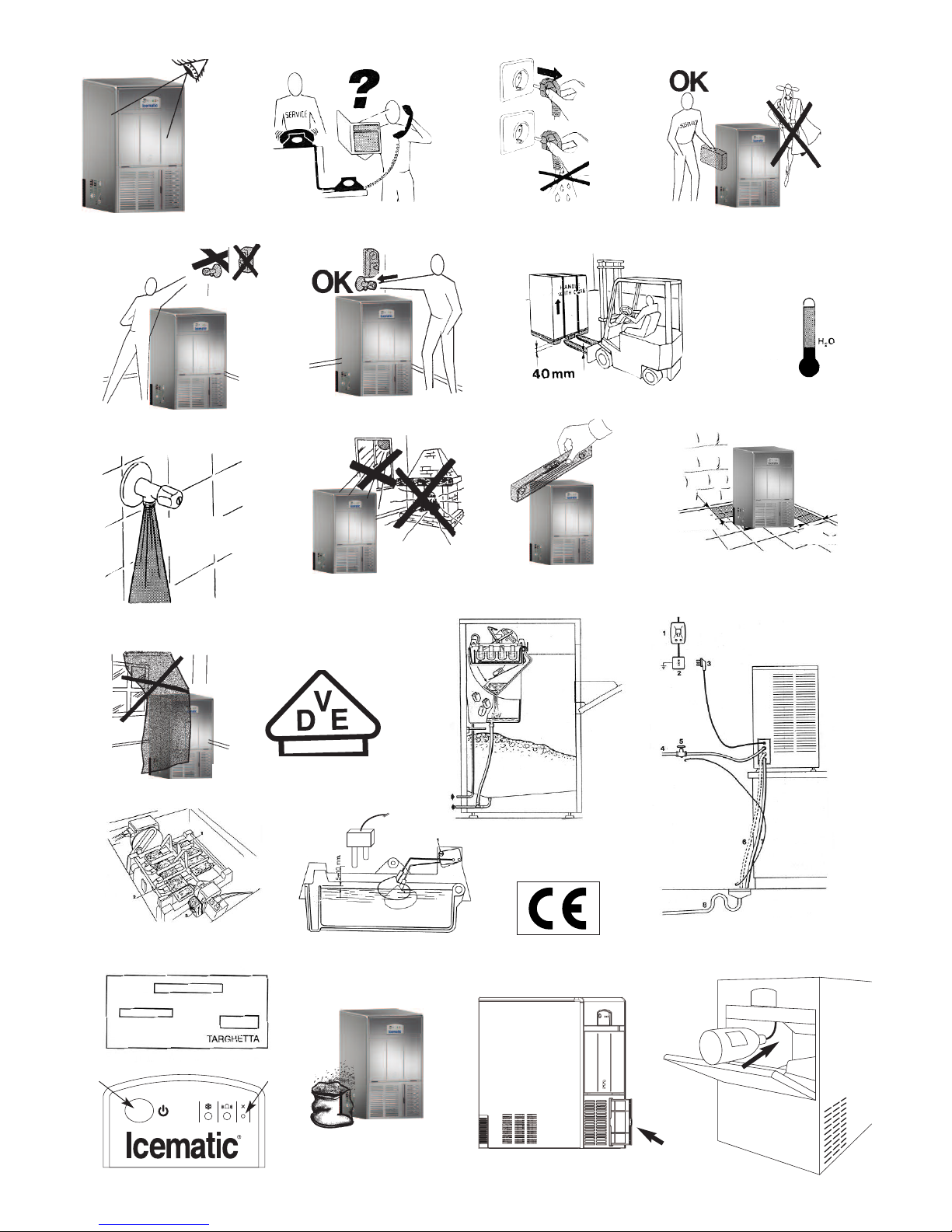
1) Controllare che il rubinetto della rete idrica di alimenta-
zione sia aperto, quindi inserire la spina di alimentazione
elettrica della macchina nella presa e accendere l’interrut-
tore di linea predisposto; la macchina inizia in funziona-
mento automatico (fig. 14) dopo aver premuto il pulsante
ON/OFF di avviamento (fig. 22).
2) Controllare che l’acqua arrivi alla vaschetta, che il sensore
e/o il galleggiante arresti l’entrata prima del trabocco e che
non esistano perdite nell’impianto e nei condotti idrici. Il
normale livello d’acqua all’interno della vaschetta è a circa
5./.10 mm. dai bordi superiori. (fig. 17)
La regolazione del livello acqua può avvenire ruotando il
micro galleggiante o il sensore acqua sull’apposita feritoia
prevista sul supporto relativo, previo allentamento della
vite di fissaggio 1 (fig. 17). Tale regolazione deve avvenire
con alimentazione elettrica disinserita.
3) Verificare che non si producano vibrazioni anormali a
causa di viteria allentata.
4)
Nel caso di necessità di intervento per perdite d’acqua, ser-
raggio viteria od altro, arrestare sempre prima il produttore.
5) Controllare un ciclo di produzione ghiaccio verificando che
i cubetti vengano scaricati nel deposito.
6) Verificare la funzionalità della sonda deposito: appoggiando
un cubetto di ghiaccio sul bulbo all’interno del contenitore il
produttore dovrebbe arrestarsi entro 1 minuto e ripartire au-
tomaticamente dopo averlo tolto, in tempo poco superiore.
7) Rimontare il coperchio tolto in precedenza.
PUL Z A E MANUTENZ ONE
Per la pulizia della carrozzeria, é sufficiente usare un panno
inumidito con un prodotto specifico, privo di cloro, per acciaio
inossidabile.
N.B. Tutte le operazioni di pulizia e manutenzione devono es-
sere eseguite previo disinserimento dell’alimentazione elet-
trica dell’apparecchio.
PUL Z A DEL CONDENSATORE AD AR A
Per valorizzare al meglio il vostro produttore in termini di resa
e durata è necessario effettuare ogni settimana la pulizia del
filtro aria posizionato nella parte frontale del produttore (vedi
fig. 23). Per la rimozione del filtro è sufficiente estrarlo e la-
varlo con un getto di acqua tiepida e asciugarlo prima del ri-
montaggio.
Non utilizzare spazzole o oggetti contundenti per la pulizia del
filtro.
È assolutamente vietato far funzionare il produttore senza il fil-
tro dell’aria per evitare il malfunzionamento.
PUL Z A DEL F LTRO ENTRATA ACQUA
Chiudere il rubinetto d’intercettazione d’acqua all’apparecchio,
staccare il tubo entrata acqua e sfilare con una pinza la retina
filtrante situata sull’elettrovalvola entrata acqua. Pulire la re-
tina con getto d’acqua e rimontarla nella propria sede.
PUL Z A DEL CONTEN TORE
Estrarre il ghiaccio dal deposito. Pulire l’interno con una spu-
gna inumidita in acqua tiepida unita ad un poco di bicarbonato
di soda; sciacquare con acqua pura ed asciugare accurata-
mente.
l C CLO D LAVAGG O E SAN F CAZ ONE.
Per ovviare ai problemi dati dalla durezza dell’acqua di ali-
mentazione e quindi la formazione di impurità sulle parti e com-
ponenti a contatto con l’acqua, la macchina e’ stata dotata di
una funzione “Self Cleaning”. Tale funzione, grazie all’azione
pulente di un prodotto specifico, una bustina di prodotto in pol-
vere e la bottiglia dosatrice, permette di mantenere pulita e
igienizzata la macchina dal calcare e dalle incrostazioni.
Per garantite una buona pulizia del fabbricatore di ghiaccio si
consiglia di eseguire il ciclo di lavaggio almeno 3-4 volte al-
l’anno in funzione della durezza dell’acqua di alimentazione.
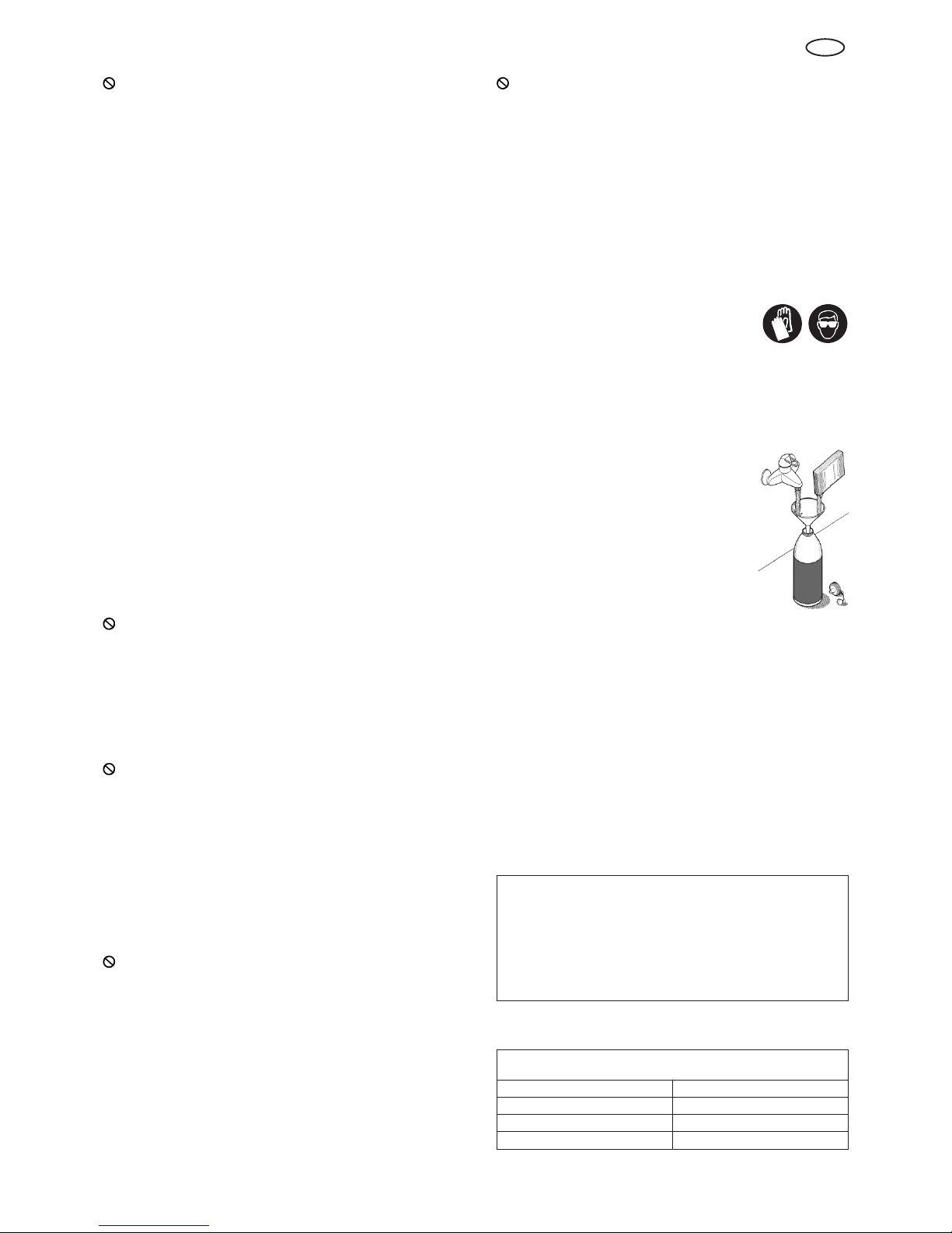
COME ESEGU RE L C CLO D LAVAGG O E SAN F CAZ ONE
.
Prendere le dovute precauzioni nel maneggiare l’acido citrico
mentre si prepara la soluzione (acqua+acido
citrico, vedi tabella) indossando guanti e oc-
chiali protettivi.
Spegnere la macchina. Togliere tutto il ghiaccio dal conteni-
tore. Servendosi del prodotto specifico e della bottiglia in pla-
stica, preparare la soluzione sciogliendo la polvere in acqua
tiepida (max. 40°C) secondo le quantità riportate nella tabella
allegata. Mescolare il tutto facendo attenzione che non si ve-
rifichino dei grumi. Accendere la macchina, premendo il pul-
sante ON/OFF e tenendo contemporanea-
mente premuto anche il pulsante di RESET
(fig. 22). Per premere il pulsante di RESET
utilizzare una spina di diametro adeguato al
foro sul quadro comandi.
Entrambi i leds lampeggiano velocemente.
Aprire lo sportello del deposito, attendere che
la bacinella ritorni in posizione di chiusura. In-
trodurre la canula nella bottiglia in tutta la sua
lunghezza nell’apposito foro (vedi fig. 24) e
scaricare tutta la miscela precedentemente
preparata, facendo pressione con le mani sulla bottiglia. Chiu-
dere lo sportello e ripremere il pulsante Reset per avviare il
ciclo di LAVAGGIO.
Una volta avviato il ciclo di lavaggio il lampeggio dei leds sarà
più lento. urante la funzione lavaggio provvedere a riscia-
quare abbondantemente il deposito.
La durata del ciclo di lavaggio e di circa 3 ore.
Una volta avviata la funzione anticalcare non è possibile in-
terrompere il ciclo di lavaggio. In caso di mancanza di ten-
sione, la macchina riprende da dove si era fermata.
Al termine del ciclo di lavaggio e risciacquo la macchina ri-
parte in ciclo freddo.
Per tutti gli interventi di manutenzione straordinaria e/o ripa-
razione (parti meccaniche, frigorifere, elettriche) che compor-
tino la regolazione e/o sostituzione di componenti, rivolgersi
sempre a un centro servizi autorizzato.
opo un lungo periodo di inattività si consiglia di eseguire un
ciclo di pulizia prima di iniziare la produzione di ghiaccio.
Quantitativi di acido citrico da miscelare con acqua
nella bottiglia per ottenere la miscela
MODELLO Q.T ACIDO CITRICO
E21-E25 200 gr.
E35 250 gr.
E45-E55 500 gr.
Se l’apparecchio dovesse rimanere inutilizzato per lunghi
periodi:
- disattivare la macchina
- togliere tutto il ghiaccio dal contenitore
- scaricare tutta l’acqua
- eseguire un’accurata pulizia
- lasciare lo sportello del contenitore leggermente aperto.

6
T
1. FUNZ ON SCHEDA ELETTRON CA
- controllo del livello del ghiaccio con sonda
- controllo della temperatura di condensazione con sonda
(stop macchina con temperatura > 60°C versione acqua; > di 70°C aria).
- Controllo della manutenzione. Si può programmare l’avviso della manutenzione dopo un numero di ore di funzionamento.
- Controllo del ciclo di lavaggio / pulizia da farsi periodicamente con comando manuale.
2. NGRESS E USC TE DELLA SCHEDA ELETTRON CA
Sonda Condensatore: con temperatura condensatore < 24°C la scheda fa ciclare il ventilatore in modo da garantire una condi-
zione ottimale della condensazione e della resa della macchina.
Errore sonda temperatura condensatore: +70°C versione condensazione Aria, +60°C versione condensazione acqua.
Quando la temperatura della sonda condensatore scende di 10°C sotto i valori massimi (vedi sopra) la macchina riparte auto-
maticamente.
Nel caso si verifichino 3 errori entro le 6 ore, la macchina si arresta definitivamente. Questo sta ad indicare che c’è un problema
funzionale grave.
Valori di resistenza delle sonde di temperatura (sonda deposito e sonda condensatore) riferiti alla temperatura ambiente:
RESET DELLA CHEDA M CROPROCESSOR
Premendo il pulsante ON/OFF .
3. CARATTER ST CHE D FUNZ ONAMENTO
All’avviamento la macchina va in brinamento e scarica l’acqua della bacinella.
Il ciclo di produzione si avvia con due minuti di ritardo che permettono un corretto bilanciamento dell’impianto frigorifero e quindi
un miglior rendimento e una migliore produzione.
urante il funzionamento della macchina, al termine di ogni sbrinamento, il carico acqua avviene con 80 secondi di ritardo, per
permettere il sottoraffreddamento dell’evaporatore.
Quando il deposito è pieno di ghiaccio, la sonda viene a contatto con i cubetti e la scheda elettronica arresta la macchina solo al
termine del ciclo di sbrinamento. Questo per avere sempre dei cubetti completamente formati e delle stesse dimensioni.
Segnalazione di allarme per i modelli versione aria/acqua:
- surriscaldamento del condensatore: la macchina va in allarme e riparte automaticamente una volta che la causa è stata ri-
mossa e/o la temperatura è rientrata nel range di funzionamento stabilito;
- errore di mancanza acqua di alimentazione: in caso di mancanza acqua di alimentazione la macchina riparte automatica-
mente dopo 60 minuti dal ripristino dell’allarme.
4. C CLO D LAVAGG O
Una volta avviata la macchina, non è possibile uscire dal ciclo di lavaggio anche se si spegne e riaccende il produttore
poiché lʼelettronica mantiene in memoria il ciclo.
Tempo di un ciclo completo di lavaggio: 3 ore
l ciclo di lavaggio è formato da: 90 minuti di lavaggio più 5 risciaqui di 15 minuti ciascuno.
Al termine del ciclo di lavaggio la macchina riparte automaticamente in ciclo freddo.
l sensore livello acqua nella bacinella lavora in presenza di acque con conducibilità compresa tra i 20 e i 1000
micro-siemens per centimetro.
l sensore di livello acqua può essere sostituito da un micro galleggiante. Lʼattacco è uguale per entrambi.
Nel caso la macchina sia alimentata con acqua addolcita (demineralizzata) si consiglia di installare il kit galleggiante
(fig. 17).
DAT TECN C PER L SERV CE
ngressi in bassa tensione 12V ngressi in alta tensione 230V/ 50HZ
Sonda condensatore Compressore
Sonda deposito Motore di Ribaltamento
Sensore livello acqua Elettrovalvola gas caldo
Micro nizio sbrinamento Elettrovalvola Acqua
Micro fine sbrinamento Motoriduttore Palette
Elettroventilatore
Scheda Elettronica
Temperatura °C Resistenza sensore Ohm
20 2762,034556
Temperatura °C Resistenza sensore Ohm
25 2200,000000
Temperatura °C Resistenza sensore Ohm
30 1765,531939

5. CARATTER ST CHE DELLʼ MP ANTO FR GOR FERO GAS FREON R404a
Medio e massimo assorbimento elettrico macchine a palette serie “E” a temperatura ambiente di 32°C.
Pressione di condensazione e temperatura di evaporazione a inizio e fine ciclo a temperatura ambiente di 32°C.
* Potenza assorbita a temperatura evaporatore di -15°C
** Espresso in litri d’acqua per ora a temperatura acqua di 15°C e ambiente di 21°C
6. AVV SO D MANUTENZ ONE PROGRAMMATA.
Il tempo di manutenzione programmata viene settato in fabbrica a 0 ore.
Per modificare questo tempo e/o azzerare la funzione di richiamo manutenzione , procedere al settaggio dei dip- switch come
da tabella allegata.
Nel caso di manutenzione programmata, per resettare e ripristinare la programmazione al valore iniziale premere il pulsante
RESET per almeno 5 secondi.
IP NOTE
1 2
1OFF Intervallo di manutenzione a 0 ore
ON
2OFF Intervallo di manutenzione a 2000 ore
ON
3OFF Intervallo di manutenzione a 6000 ore
ON
4OFF Intervallo di manutenzione a 3500 ore
ON
7
T
MMAACCCCHHIINNAA
TTIIPPOO DDII GGAASS
AASSSSOORRBBIIMMEENNTTOO MMAAXX..
AAMMPPEERREE
AASSSSOORRBBIIMMEENNTTOO
MMEEDDIIOO AAMMPPEERREE
PPRREESSSSIIOONNEE DDII
CCOONNDDEENNSSAAZZIIOONNEE
AALLLL’’AAVVVVIIAAMMEENNTTOO
((BBAARRSS))
TTEEMMPPEERRAATTUURRAA DDII
EEVVAAPPOORRAAZZIIOONNEE
AALLLL’’AAVVVVIIAAMMEENNTTOO
((°°CC))
PPRREESSSSIIOONNEE DDII
CCOONNDDEENNSSAAZZIIOONNEE
FFIINNEE CCIICCLLOO ((BBAARRSS))
TTEEMMPPEERRAATTUURRAA DDII
EEVVAAPPOORRAAZZIIOONNEE
FFIINNEE CCIICCLLOO
((°°CC))
CCOONNSSUUMMOO EELLEETTTTRRIICCOO
2244 HHRRSS//KKWW **
CCUUBBEETTTTII PPEERR CCIICCLLOO EE
PPEESSOO DDII UUNN CCUUBBEETTTTOO
CCOONNSSUUMMOO AACCQQUUAA ****
EE2211134 A 2 A 1 8 A 11 5 -3 3 9 -17 7 5 15/19 GR 6
EE2255134 A 1 6 A 1 4 A 11 -2 9 -13 5 8 15/179 GR 2 8
EE3355134 A 2 7 A 2 1 A 14 -2 10 -15 8 6 20/17 GR 4 7

8
T
7. CONNESS ONE DE CAV ELETTR C E DE COMPONENT ALLA SCHEDA ELETTRON CA
ATTENZ ONE: R SPETTARE LE CONNESS ON CON COLOR DE CAV ELETTR C .
8. K T LAVAGG O
Il kit è composto da una bottiglia in plastica con
tubo in gomma, una confezione di acido citrico da 1 kg.
e le istruzioni per il ciclo di lavaggio.
Sensore livello galleggiante
Micro ribaltamento
Cumune micro
Micro sbrinamento
Sonda deposito ghiaccio
Sonda condensatore
Azzurro
Marrone
Arancio
Nero
Bianco
Rosso
ip. Switch
per set ore
manutenzione

GB
ATTENT ON!!!!
THE FOLLOW NG OPERAT ONS AND THOSE H GHL GHTED BY THE SYMBOL AT THE S DE
ARE STR CTLY FORB DDEN FOR WHOEVER USES THE MACH NE
SUCH OPERAT ONS MUST BE PERFORMED EXCLUS VELY BY QUAL F ED PERSONNEL
1. ELECTR CAL CONNECT ONS
2. WATER CONNECT ONS
3. MACH NE NSTALLAT ON
4. MACH NE TEST NG
5. REPA R NG MACH NE COMPONENTS
AND PARTS
6. D SASSEMBL NG THE MACH NE
AND/OR TS COMPONENTS
7. ADJUSTMENTS AND SETT NGS
8. MACH NE CLEAN NG AND
MA NTENANCE RELAT VE TO THE
FOLLOW NG PARTS AND
COMPONENTS:
ELECTR CAL
ELECTRON C
MECHAN CAL
COOL NG
9
GENERAL NFORMAT ON
The ice making machines approved by V E bear the symbol
shown in fig. 13 on the packing, the serial number plate and
the machine structure.
This appliance is not intended to be used by persons -
including children - with reduced physical, sensory or mental
capabilities, or with no experience and knowledge, unless they
have been instructed on how to use the appliance and are
supervised by a person who is responsible for their safety.
Children should be supervised to ensure that they do not play
with the appliance
NSTALLAT ON
Implement the following operations before activating the ice
maker:
1) Verify that the ice maker has not been damaged during
transport (fig. 1).
2) Remove all the material provided from the container:
supply pipe, drain pipe, documentation and any
accessories.
3) Clean inside the container with a sponge dampened with
warm water and a little sodium bicarbonate; rinse with
clean water and dry carefully.
4) Place the ice maker in its definite location and ensure that
it is perfectly level (fig. 10).
5) Use the new set of mobile junctions (water pipe) supplied
with the appliance. The old set of junctions must not be
reused.
6) Install the water connections before the electrical
connections.
7) Connect the 3/4’’ supply pipe (supplied) to the machine
and to the cold drinking water supply line.
For practical and safety purposes, it is advisable to install
a shut-off valve (not supplied by CastelMac) (fig. 15: 1.
switch; 2. socket; 3. electrical plug; 4. water supply; 5.
valve; 6. water drain from the condenser: water-cooled
version; 7. water drain from the container; 8. water drain
with open siphon).
8) Apply the flexible pipe (supplied) with a 20 mm inner
diameter and of adequate length (not more than 1 metre
from the machine) to the water drain fitting of the machine
in order to reach the drain well (fig. 15).
CONNECT NG THE APPL ANCE TO THE MA NS
f the power supply cable is damaged, it must be replaced
by qualified personnel to prevent any hazards to persons
THERE MUST BE A D FFERENT AL SW TCH
(CUT-OUT) N THE ELECTR CAL SYSTEM.
- Install the machine in a position that the ventilation of the
cooling unit is not obstructed in any way (only for air-
cooled machines) (fig. 11).
- o not install the machine in a dusty room as the
condenser of the cooling unit can be easily clogged (only
for air-cooled machines) (fig. 20).
- If the machine is installed in an area where the drinking
water has a high content of salt solutions, follow the
manufacturer's instructions in order to minimise the
problem.
- To prevent the ice from absorbing bad smells and tastes,
never store food, bottles, etc. in the container.
- o not leave the ice container door open during normal
operation.
ATTENT ON:
Connect only to the drinking water mains
NOTE
When choosing where to install the appliance, make sure
that:
a) the room temperature never drops below 10°C (50°F)
and does not exceed 40°C (100° F).
b) the water pressure must be no less than 15°C (50°F)
and no more than 32°C (90°F) (fig. n° 7).
c) the supply water pressure must be no less than 0,1
MPa (1 bar) and no more than 0,5 MPa (5 bar).
Should the pressure exceed 0,5 MPa, install a
pressure reducer on the machine water supply (fig. 8).
d) the machine is away from heat sources and in a well-
ventilated area (fig. 9).
ATTENT ON:
o not start the appliance before the technician intervenes
(fig. 4).
EC
OUR PRODUCTS COMPLY W TH D RECT VES
2006/95/EC - 2004/108/EC THEREFORE THEY ALSO
BEAR THE MARK NG ON THE MANUAL COVER.

ACT VAT NG THE MACH NE
Implement the following operations before activating the ice
maker:
1) look at the pictures:
a) remove the cover by loosening the relative fastening
screws.
b) release the gear motor, the blades and the float (where
applicable) by removing the factory-set stops 1, 2 and
3, which have been fixed to prevent damage during
transport (fig. 16). For the water-cooled models
connect also the second fitting to the water outlet,
which conveys the water coming from the condenser.
Implement a minimum inclination of 3% to the pipes for
perfect water flow from the appliance, ensuring that these
have no narrowing sections and are not siphoned. It is
advisable that the pipes drain into an open siphon (fig. 15).
2) Connect the machine to the power supply after having
verified that the mains voltage corresponds to that on the
serial number plate on the rear panel of the appliance.
The maximum voltage variation tolerance allowed is ±
10% of the rated value.
Provide a power supply circuit to the machine, with its
own bipolar main switch and a minimum of 3 mm contact
opening. The machine should also have its own fuse or
automatic protection and an earthed plug. All must be
sized according to the amperage indicated on the serial
number plate (fig. 19). The socket must be easily
accessible.
OPERAT ON
Simply press the ON/OFF button to start and stop the
machine.
Alarm signals for air / water models
- Overheating condenser: the machine restarts
automatically once the alarm has been resolved. The
cause may be due to: clogged air filter, faulty fan, room
temperature too high, no water (only in the water
version).
- Water error: if there is no water, the machine restarts
automatically 60 minutes after the alarm is triggered.
N.B.: You can exit from the alarm status after having
disconnected / connected the power supply
(ON/OFF button).
The machine stops when the container is full. The sensor
of the container is controlled by the control board and
stops the machine when the ice comes in contact with it.
The machine stops at the end of the defrosting cycle.
The Icematic ice cube makers can be easily adapted to the
furnishing of every room.
The ice cubes are formed around the fingers of the evaporator,
inside a tray filled with water and continuously moved by
revolving blades.
The level of the water in the tray is kept constant by a float
connected to a microswitch that controls the opening and
closing of a water inlet electrovalve of the water supply.
When the ice cubes reach the required dimensions, they come
in contact with the revolving blades that cause the relative
gear motor to swing, which stresses a micro switch and
simultaneously causes the following through a relay:
- the delivery of hot gas to the evaporator by an electrovalve
opening, which leads to the cubes gradually dropping off
the fingers of the evaporator.
- the tilting of the water tray connected by means of a lever
to a gear motor.
The cubes drop and slide on a slanting grid inside the tray and
are conveyed into the container beneath.
The remaining water in the tray is collected into the relative
pan on one side of the container and conveyed towards the
drain. The tray automatically returns to its horizontal position
after about a minute and fills with water till the pre-set level. In
the meantime, the hot gas valve closes and the ice forming
cycle proceeds smoothly; a complete cycle can vary from
about 15’ to about 25’ depending on the water and room
temperatures.
The quantity of ice inside the container is controlled by the
electronic sensor fixed on one side of the container itself;
when the ice cubes reach the level of the bulb, the machine
stops completely. After removing enough ice from the
container for no cubes to be in contact with the bulb, the
appliance will resume its normal production.
The RESET button has the following functions (X):
1. Reset maintenance alert
2. Reset the start of the wash cycle (refer to instructions)
CONTROL PANEL S GNALS
Start stand-by
LL= flashing slowly • LV= flashing quickly
LA= alternate flashing
NOTE: After removing the ice cubes, remove any remai-
ning ice on the control bulb for production to resume quic-
ker.
10
GB
Function Sta-
tus
Led 1
Green
Led 2
Red Notes
Machine on ON OFF
Applicable to all condi-
tions that are not in
alarm/error or full contai-
ner status
Full
Container LL OFF Machine stopped
Container and
condenser
temperature
sensor error
OFF LL “Out of range” tempera-
ture sensor
Condenser
overheating
error
OFF ON
No water
error LL ON The signal is triggered
after attempting to restart
Maintenance
warning LA LA
The pre-set number of
operating hours has been
reached. The mainte-
nance alert has priority
over the signalling of:
start cycle, machine on
and full container
Wash / clean LV LV Signalled during the wash
routine
LV OFF Waits to start after
switch-off

11
GB
SERV CE NFORMAT ON
THE FOLLOW NG OPERAT ONS MUST BE
MPLEMENTED SOLELY BY OUR “ CEMAT C” QUAL F ED
PERSONNEL N YOUR AREA (fig. 2).
1) Verify that the water supply valve is open, then plug in the
machine and switch on the main switch; the appliance
starts-up in automatic mode (fig. 14) after having pressed
the ON/OFF start button (fig. 22).
2) Verify that the water reaches the tray, the float stops the
water before the overflow and that there are no leaks in
the system and in the water channels. The normal level of
water inside the tray is about 5/10 mm from the upper
edge (fig. 17).
The level of water can be adjusted by rotating the
microfloat or the water sensor on the slot on the relative
support after having loosened fastening screw 1 (fig. 17).
This adjustment must be implemented after having
disconnected the power supply.
3) Verify that there is no abnormal vibration due to loose
screws.
4)
Always stop the appliance before implementing any
operations to resolve water leaks, tighten screws, etc.
5) Verify an ice production cycle ensuring that the cubes are
conveyed into the container.
6) Verify that the container sensor functions properly: place
an ice cube on the bulb inside the container; the appliance
should stop within 1 minute and restart automatically
shortly after removing it.
7) Replace the cover previously removed.
CLEAN NG AND MA NTENANCE
Use a cloth dampened with a specific chlorine-free product for
stainless steel to clean the structure.
N.B. isconnect the electrical power supply from the
appliance to perform maintenance and cleaning operations.
CLEAN NG THE A R CONDENSER
To make the most of your appliance in terms of efficiency and
durability, the air filter at the front of the machine must be
cleaned every week (refer to fig. 23). The filter is removed by
simply extracting it (refer to fig. 22). Simply wash the filter with
a water jet of warm water and dry it before setting it back in
place.
o not use brushes or blunt objects to clean the filter.
It is absolutely forbidden to operate the producer without the
air filter to prevent malfunctioning.
CLEAN NG THE WATER NLET F LTER
Close the water shut-off valve of the appliance, disconnect the
water inlet pipe and remove the filter screen that is on the
water inlet electrovalve with a pair of pliers. Clean the screen
with a water jet and reassemble it into its place.
CLEAN NG THE CONTA NER
Remove the ice from the container. Clean inside the container
with a sponge dampened with warm water and a little sodium
bicarbonate; rinse with clean water and dry carefully.
THE WASH AND SAN TAT ON CYCLE
The machine has been equipped with a “Self Cleaning”
function in order to remedy the problems deriving from the
hardness of the supply water and therefore, the formation of
impurities on the components and parts that are in contact
with the water.
Thanks to the cleaning action of a specific product, which
comes in the form of powder in a sachet and a dosing bottle,
this function keeps the machine clean and sanitised from
limescale and deposits.
To guarantee proper cleaning of the ice maker one
recommends carrying out the wash cycle at least 3-4 times a
year, according to the hardness of the water supply.
MPLEMENT NG THE WASH AND SAN TAT ON CYCLE.
Adopt proper precautions when handling
citric acid whilst preparing the solution
(water+ citric acid, see the table). Wear
protective gloves and goggles.
Turn the machine off. Remove all ice from the container. Using
the specific product and the plastic bottle, prepare the solution
by dissolving the powder in warm water (max. 40°C),
according to the quantities shown on the attached table.
Mix well whilst ensuring that no lumps are
formed.
Switch the machine on by pressing the
ON/OFF button whilst keeping the RESET
button pressed (see img. 22). Press the reset
button using a pin of suitable diameter to
enter the appropriate hole.
Both LE s will flash quickly. Open the
deposit hatch, wait for the tray to go back into
closing position. Insert the cannula into the
bottle throughout its length in the appropriate
hole (see img. 24) and drain all the previously prepared
descaling mixture, applying pressure with your hands on the
bottle. Close the hatch and repress the Reset button to start
the WASHING cycle.
Once the wash cycle is started, LE flashing will slow down.
uring the wash function, rinse the container thoroughly.
The duration of the washing cycle is of approximately 3 hours.
Once the descaling function has started it is not possible to
interrupt the washing cycle. In case of a power-cut, the
machine resumes from where it had stopped.
At the end of the washing and rinsing cycle the machine
restarts in the cold cycle.
For all extraordinary maintenance and/or repairs (mechanical,
cooling and electrical parts) that require adjustments and/or
components to be replaced, always refer to an authorised
service centre.
After a long period of inactivity one recommends to perform a
cleaning/descaling cycle before commencing ice production.
Quantities of citric acid to be mixed with water
in the bottle to obtain the mixture
MODEL C TR C AC D Q.TY
E21-E25 200 gr.
E35 250 gr.
E45-E55 500 gr.
If the appliance should not be used for long periods of time:
- disable the machine
- remove all the ice from the container
- drain all the water
- thoroughly clean the machine
- leave the door of the container ajar

12
GB
1. ELECTRON C BOARD FUNCT ONS
- ice level check with probe
- condensing temperature check with probe (machine stop with temperature > 60°C water version; > of 70°C air).
- Maintenance check. The maintenance alert can be programmed after a certain number of hours of functioning.
- Wash/cleaning cycle check to be carried out periodically with manual control.
2. ELECTRON C BOARD NPUTS AND OUTPUTS
Condenser probe: with condenser temperature < 24°C, the board makes the fan turn guaranteeing optimal condition of conden-
sation and machine yield.
Condensing temperature probe failure: +70°C air cooling version , +60°C water cooling version.
When the sensor temperature drop below than 10°C under the maximum values (see above) the machine re-start automatically.
In case of 3 errors occur within 6 hours running period, the machine stop definitively.
This mean that there is a serious functional problem.
Resistance values of the temperature probes (deposit probe and condenser probe) with reference to the room temperature:
PCB M CROPROCESSOR RESET
Pressing the ON/OFF button.
3. OPERAT ON CHARACTER ST CS
On the starting the machine goes into defrosting and discharge the water pan.
The production cycle start with two minutes of delay that allow a correct balancing of the refrigeration system and therefore a
good output and a best production.
uring the machine operation, at the end of every defrosting , the water load happens with 80 seconds of delay, this to allow the
evaporator subcooling.
When the bin is full of ice, the probe comes in contact with the ice and the electronic card stop the machine only on the end of
defrosting time. This to always have the cubes completely formed and at the same dimensions.
Signalling of alarms for the models air and water version:
- condenser overheating : the machine goes to alarm and it restart again automatically once that the cause has been remo-
ved and / or the temperature has re-entered in the range of established operation;
- error of not water feeding: in case of lack of water the machine automatically start again after 60 minutes from the alarm
reset .
4. WASH NG CYCLE
Once the machine is started, it is not possible to exit the washing cycle even if the ice maker is switched on and off, as
the electronic keeps the cycle in the memory.
Time of complete washing cycle: 3 hours
The washing / cleaning cycle is formed of: 90 minutes of washing plus 5 rinsing of 15 minutes each.
At the end of the washing cycle the machine automatically start again in cold cycle.
The water level sensor inside the basin works with waters with conductivity between 20 and 1000 micro-siemens per
centimetre.
The water level sensor can be replaced by a microfloat. Connection is the same for both.
f the machine is supplied with softened water (demineralised), float kit installation is recommended (fig. 17)
TECHN CAL SERV CE DATA
Low voltage inputs 12V High voltage inputs 230V/50HZ
Condenser probe Compressor
Container Probe Tilting Motor
Water level sensor Hot gas electrovalve
Defrosting start micro Water electrovalve
Defrosting end micro Blades gear motor
Electric fan
Electronic board
Temperature °C Sensor resistance Ohm
20 2762,034556
Temperature °C Sensor resistance Ohm
25 2200,000000
Temperature °C Sensor resistance Ohm
30 1765,531939

13
GB
5. FEATURES OF THE GAS REFR GERATOR PLANT FREON R404a
Medium and maximum series "E" blade machines absorption at room temperature of 32°C.
Condensing pressure and evaporator temperature cycle start and end at room temperature of 32°C.
* Absorbed power at evaporator temperature of -15°C
** Expressed in water litres per hour at water temperature of 15°C and room temperature of 21°C
6. PROGRAMMED MA NTENANCE WARN NG.
The programmed maintenance time is set at 0 hour by the manufacturer.
In order to modify this time and/or reset the maintenance
recall function; proceed with dip-switch set-up, as shown in the attached table.
In case of programmed maintenance, to reset and to restore the programming to the initial value it's necessary to press the
RESET button for at least 5 seconds.
IP NOTE
1 2
1OFF Interval of maintenance to 0 hour
ON
2OFF Interval of maintenance to 2000 hours
ON
3OFF Interval of maintenance to 6000 hours
ON
4OFF Interval of maintenance to 3500 hours
ON
MMAACCHHIINNEE
GGAASS
MMAAXX.. AAMMPPEERREE
MMEEDDIIUUMM AAMMPPEERREE
CCOONNDDEENNSSIINNGG
PPRREESSSSUURREE
SSTTRRAARRTTIINNGG CCYYCCLLEE
((BBAARRSS))
EEVVAAPPOORRAATTIIOONN
TTEEMMPPEERRAATTUURREE
SSTTAARRTTIINNGG CCYYCCLLEE ((°°CC))
CCOONNDDEENNSSIINNGG
PPRREESSSSUURREE EENNDD
CCYYCCLLEE ((BBAARRSS))
EEVVAAPPOORRAATTIIOONN
TTEEMMPPEERRAATTUURREE EENNDD
CCYYCCLLEE ((BBAARRSS))
EELLEECCTTRRIICCAALL
CCOONNSSUUMMPPTTIIOONN
OONN 2244 HHRRSS//KKWW **
CCUUBBEESS FFOORR CCYYCCLLEESS
AANNDD WWEEIIGGHHTT SSIINNGGEELL
CCUUBBEE IINN GGRR
WWAATTEERR
CCOONNSSUUMMPPTTIIOONN ****
EE2211134 A 2 A 18 A 11 5 -3 3 9 -17 75 15/19 GR 6
EE2255134 A 1 6 A 1 4 A 11 -2 9 -13 5 8 15/179 GR 2 8
EE3355134 A 2 7 A 2 1 A 14 -2 10 -15 8 6 20/17 GR 4 7

14
GB
8. CLEAN NG K T
the kit is composed of a plastic bottle with rubber pipe,
one confection of acid citric (1 kg.),
and instructions for the cleaning procedure.
7. CONNECT ON OF ELECTR CAL CABLES AND COMPONENTS TO THE PC BOARD
CAUT ON: OBSERVE THE CONNECT ON W TH THE COLORS OF ELECTR C CABLES.
Float level sensor
Micro tip
Cumun micro
Micro defrost
Probe deposit ice
Condenser probe
Blue
Brown
Orange
Black
White
Red
ip. Switch
to set the
maintenance hours

DE
ACHTUNG!!!!!!
FOLGENDE ARBE TSGÄNGE, UND D E DURCH E N NEBENSTEHENDES SYMBOL
GEKENNZE CHNETEN, DÜRFEN AUF KE NEN FALL VOM BED ENUNGSPERSONAL DER MASCH NE
VORGENOMMEN WERDEN, SONDERN AUSSCHL EßL CH VON AUTOR S ERTEM NSTALLAT ONS-
TECHN SCHEN PRSONAL.
1. ELEKTR SCHER ANSCHLUSS
2. WASSERANSCHLUSS
3. NSTALLAT ON
4. MASCH NENTEST
5. REPARATUR ALLER TE LEN UND
WERKTE LE DES GERÄTES
6. DEMONTAGE DES GERÄTES BZW.
SE NER BAUTE LE
7. REGUL ERUNG UND E CHUNG DES
GERÄTES
8. WARTUNG UND RE N GUNG DES GE-
RÄTES ENTSPRECHEND HRER
TE LE UND KOMPONENTEN:
ELEKTR SCHE,
ELEKTRON SCHE,
MECHAN SCHE,
GEFR ER-.
15
ALLGEME NE NFORMAT ONEN
ie Eismaschinen sind durch V E und GS zugelassen und
tragen das in Abb. 13 dargestellte Symbole auf der Verpa-
ckung, auf dem Typenschild und auf der Karosserie.
ieses Gerät ist nicht dafür bestimmt, von Personen (ein-
schließlich Kindern) benutzt zu werden, die aufgrund ihrer
physischen, sensorischen oder geistigen Fähigkeiten oder
ihrer Unerfahrenheit und Unkenntnis nicht in der Lage sind,
das Gerät sicher zu bedienen, es sei denn sie werden durch
eine für ihre Sicherheit zuständige Person beaufsichtigt und
erhielten von ihr Anweisungen, wie das Gerät zu benutzen ist.
Kinder sollten beaufsichtigt werden, um sicherzustellen, dass
sie nicht mit dem Gerät spielen.
NSTALLAT ON
Vor der Inbetriebnahme folgende Hinweise für die Aufstellung des
Gerätes beachten:
1) Gerät auf Transportschäden untersuchen (Abb. 1).
2) Zubehör aus dem Vorratsbehälter entnehmen: Versorgungs- und
Abflussschläuche, Unterlagen und eventuelles Zubehör.
3) Vorratsbehälter mit einem Schwamm, warmem Wasser und
einem Sodabikarbonat auswaschen. Mit klarem Wasser nach-
spülen und gut austrocknen.
4) Gerät an dem vorgesehenen Platz aufstellen und waagerecht
ausrichten (Abb. 10).
5) Benutzen Sie den neuen Bausatz der mobilen Verbindun-
gen (Wasserleitung), der mit dem Gerät mitgeliefert wird.
er alte Bausatz darf nicht wiederverwendet werden.
6) ie hydraulischen Anschlüsse vor den elektrischen aus-
führen.
7) en beiliegenden Anschlussschlauch 3/4” am Gerät und
am Trinkwasseranschluss anschließen.
Aus praktischer Sicht und für die Sicherheit empfiehlt es
sich, ein Absperrventil vorzusehen (gehört nicht zum Lie-
ferumfang) (Abb. 15: 1. Schalter; 2. Steckdose; 3. Stecker;
4. Wassereinlass; 5. Absperrventil; 6. Wasserabfluss vom
Kondensator: wasserkühlende Ausführung; 7. Wasserab-
fluss vom Behälter; 8. offener Wasserabfluss).
8) Abflussstutzen über einen Plastikschlauch (nicht länger
als 1 Meter von der Maschine entfernt) von 20 mm lich-
tem urchmesser zu einem Ablauf (Abb. 15) führen.
ANSCHLUSS DES GERÄTES AN D E STROMVERSORGUNG
Bei einer eventuellen Beschädigung des elektrischen
Stromkabels muss es durch Fachpersonal ersetzt wer-
den, um jegliche Gefahr für Personen auszuschließen.
D E ELEKTR SCHE ANLAGE MUSS M T E NEM
D FFERENZ ALSCHALTER AUSGESTATTET SE N
(S CHERUNG).
- ie Maschine an einem Ort aufstellen, wo die Ventilation
der Kühleinheit nicht verdeckt wird (nur für luftgekühlte
Maschinen) (Abb. 11).
- ie Maschine nicht an staubigen Orten aufstellen, da sich
hier der Kondensator der Kühleinheit schnell verstopfen
kann (nur bei luftgekühlten Maschinen ) (Abb. 20)
- Sollte die Maschine an einem Ort aufgestellt sein, wo das
Trinkwasser einen hohen Salzgehalt haben, sollten die
Anweisungen der Herstellerfirma abgewartet werden,
damit Störungen minimal gehalten werden können.
- In dem Nahrungsmittelbehälter keine Flaschen oder ähn-
liches aufbewahren, damit das Eis keinen schlechten Ge-
ruch oder Geschmack annehmen kann.
- Während des normalen Betriebes die Klappe des Eisbe-
hälters nicht offen stehen lassen
ACHTUNG:
Anschluss nur an das Trinkwassernetz
CE
: UNSERE PRODUKTE ENTSPRECHEN DEN BE-
ST MMUNGEN 2006/95/CE - 2004/108/CE UND TRAGEN
DAHER DAS ZE CHEN AUF DEM UMSCHLAG DER BE-
D ENUNGSANLE TUNG.
ACHTUNG:
as Gerät nicht vor dem Eingriff des technischen Perso-
nals in Betrieb nehmen (Abb. 4)
W CHT G
Bei der Auswahl des Installationsraums des Gerätes muss
sichergestellt werden, dass:
a) die Raumtemperatur sinkt nicht unter 10°C (50°F) und
steigt nicht über 40°C (100°F)
b) die Wassertemperatur sollte nicht unter 10°C (50°F)
und nicht über 32°C (90°F) sein (Abb. 7).
c) der Wasserversorgungsdruck darf nicht unter 0,1 MPa
(1 bar) liegen und 0,5 MPa (5 bar) nicht überschreiten.
Sollte der Druck 0,5 MPa überschreiten muss ein
Druckminderer an die hydraulische Versorgung der
Maschine angebracht werden.
d) in der Nähe der Maschine dürfen keine Wärmequellen
vorhanden und Luftzirkulation muss gegeben sein
(Abb. 9).

NBETR EBNAHME
Vor der Inbetriebnahme folgende Hinweise für die Aufstellung
des Gerätes beachten:
1) Zeichnungen nachschauen.
a) eckel nach Lösen der beiden Schrauben abnehmen.
b) Transportblockierungen 1, 2, 3, von Paddelmotor, Pad-
deln und Schwimmer entfernen (Abb. 16) Bei Ausfüh-
rungen mit Wasserkühlung muss an den Abfluss auch
einen zweiten Anschluss haben, der das Wasser aus
dem Kondensator ableitet
Für einen richtigen Wasserabfluss muss eine Neigung der
Leitungen von min. 3% vorgesehen werden, wobei darauf
geachtet werden muss, dass diese keine Knicke oder Ver-
schlüsse aufweisen. Es ist angemessen, dass die Leitun-
gen durch einen offenen Siphon ableiten (Abb. 15).
2) Vor dem Netzanschluss der Maschine ist zu überprüfen,
dass die vorhandene Spannung mit den Angaben des Ty-
penschildes auf der Rückseite des Gerätes übereinstimmt.
Die maximale zugelassene Toleranz der Spannungsab-
weichung beträgt ± 10% vom Nennwert.
Für das Gerät muss ein elektrischer Versorgungskreis-
lauf mit einem doppelpoligen Hauptschalter, einer Unter-
brechung der Kontakte von min. 3mm sowie einer
Sicherung oder automatischen Schutz und einer geerde-
ten Steckdose vorhanden sein. Alles muss für die Strom-
stärke geeignet sein, die auf dem Schild der
Fabrikationsnummer verzeichnet ist (Abb. 19). Die Steck-
dose sollte einfach zu reichen sein.
ARBE TSWE SE
Zum Ein- und Ausschalten der Maschine ist lediglich der
ON/OFF-Schalter zu drücken .
Alarmmeldungen für die Modelle Ausführung Wasser / Luft
- Temperaturüberschreitung Kondensator: das Gerät
schaltet sich automatisch wieder ein sobald der Grund
der Alarmmeldung beseitigt wurde. Auslöser können
sein: Luftfilter verstopft, Ventilator defekt, Raumtem-
peratur zu hoch, Wasser fehlt (nur bei der Ausführung
mit Wasser).
- Fehler Wasser: sollte Leitungswasser fehlen, schaltet
sich das Gerät 60min nach der Alarmmeldung auto-
matisch wieder ein.
W CHT G: Es ist möglich die Alarmbedingungen abzu-
wenden ohne die Stromversorgen ab- und
wieder einzuschalten (Taste ON/OFF).
Ausschalten des Gerätes aufgrund eines vollen Behäl-
ters. Die Sonde des Behälters steuert von der elektroni-
schen Leiterplatte aus die Abschaltung des Gerätes,
sobald Eis mit ihr in Berührung kommt. Das Gerät schal-
tet sich am Ende des Entfrostungszyklus ab.
ie Eiswürfelerzeuger sind besonders kompakt. Sie lassen
sich daher leicht in jede Einrichtung einfügen.
ie Eiswürfel entstehen an den Fingern eines Verdampfer, die
in eine mit Wasser gefüllte Wanne hineinragen, welches durch
drehende Paddel ständig in Bewegung gehalten wird.
er Wasserstand wird durch einen Schwimmer konstant ge-
halten, der über einen Mikroschalter das Wasser-Magnetven-
til steuert.
Wenn die Eiswürfel die vorgesehene Größe erreicht haben
und die Paddel berühren, bewegt sich der Paddelmotor und
schaltet über einen Mikroschalter das Relais ein. adurch ge-
schieht Folgendes:
- heißes Gas strömt durch das geöffnete Magnetventil in
den Verdampfer. Er wird erwärmt und die Eiswürfel lösen
sich.
- der Wannenmotor läuft an und schwenkt die Wanne ab-
wärts.
ie Eiswürfel werden durch das Ablenkgitter in den Vorrats-
behälter gelenkt.
as in der Wanne verbliebene Wasser gelangt in den Was-
serbehälter an der Seite des Vorratsbehälters und von dort in
den Abfluss. ie Wanne bewegt sich nun automatisch nach
etwa einer Minute in die Horizontale zurück und füllt sich bis
zu dem eingestellten Wasserhöchststand. Inzwischen ist das
Heißgasventil geschlossen und der neue Gefriervorgang be-
ginnt. ie Zeit für einen kompletten Programmablauf liegt zwi-
schen 15’ und 25’ Minuten in Abhängigkeit von der Wasser-
und der Umgebungstemperatur.
ie Füllung des Vorratsbehälters wird durch einen Thermo-
statfühler überwacht, der an einer Seitenwand angebracht ist.
Sobald der Fühler von Eis berührt wird, wird die Eisproduk-
tion unterbrochen. Erst wenn soviel Eis entnommen wurde,
dass der Fühler wieder frei ist, arbeitet das Gerät automatisch
weiter.
ie Taste RESET hat folgende Funktionen (X):
1. Reset Hinweis Wartung
2. Reset Beginn Reinigungszyklus (siehe Anleitungen)
MELDUNGEN AUF DER SCHALTFLÄCHE
LL= langsames Aufleuchten • LV= schnelles Aufleuchten
LA= unterschiedliches Aufleuchten
W CHT G: Für eine schnelle Wiederaufnahme der Produk-
tion, nach der Entnahme den Kontrollfühler von eventuellen
Eisrückständen befreien.
16
DE
Statusfunktion LE 1 Grün LE 2 Rot Anmerkungen
Gerät eingeschaltet ON OFF
Gilt für alle Zustände, die
nicht Alarmen/Fehlern oder
einem vollen Behälter be-
treffen
Behälter voll LL OFF Gerät ausgeschaltet
Fehler Sonde
Temperatur
Behälter und
Kondensator
OFF LL Sonde Temperatur “out of
range”
Fehler
Temperaturüberschreitung
Kondensator
OFF ON
Fehler kein Wasser LL ON
ie Meldung wird angezeigt
nach Versuch Gerät wieder
einzuschalten
Hinweis
Wartung LA LA
Anzahl der vorgegebenen
Betriebsstunden erreicht.
ie Wartungsmeldung hat
Vorrang vor den Meldun-
gen: Start Zyklus, Gerät ein-
geschaltet, Behälter voll
Waschen / Reinigung LV LV
Es wird angezeigt wenn das
Gerät sich in Routinereini-
gung befindet
Warten Start LV OFF Warten auf Neustart nach
dem Ausschalten

H NWE SE FÜR DEN “SERV CE”
DE FOLGENDEN E NGR FFE DÜRFEN NUR VON FACH-
KRÄFTEN UNSERER “ CEMAT C” GEB ETSVERTRE-
TUNG AUSGEFÜHRT WERDEN (Abb. 2).
1) Wasserabsperrventil öffnen und Netzstecker einstecken.
as Gerät nimmt automatisch seinen Betrieb auf (Abb.
14), nachdem die Betriebstaste ON/OFF gedrückt wurde
(Abb. 22).
2) Sicherstellen, dass das Wasser an der Wanne angelangt,
dass der Sensor bzw. er Schwimmer den Eintritt vor dem
Überlaufen stoppt und das keine Leckagen an der Anlage
und an den Wasserleitungen vorliegen. as normale Was-
serniveau in der Wanne beträgt circa 5 / 10 mm an den
oberen Rändern (Abb. 17)
er Wasserstand kann nach dem Lösen der Schrauben 1
(Abb. 17) durch Schwenken des Schwimmschalters ver-
ändert werden. iese Einstellung nur mit abgeschalteter
Stromzufuhr vornehmen.
3) Prüfen, ob Nebengeräusche auftreten. iese werden
meist durch gelockerte Schrauben verursacht.
4)
Keine Arbeiten am Gerät durchführen während dieses unter
Spannung steht.
5) Arbeitsablauf des Gerätes kontrollieren. Prüfen, ob alle
Eiswürfel in den Vorratsbehälter gelangen.
6) ie Funktion der Sonde im Behälter prüfen: einen Eiswür-
fel an das Thermostat im Inneren des Behälters halten.
as Gerät sollte sich innerhalb von 1min abschalten und
automatisch wieder einschalten, nachdem das Eis entfernt
wurde, nach nicht mehr als einer weiteren Minute.
7) eckel wieder aufsetzen.
RE N GUNG UND WARTUNG
Für die Reinigung des Aufbaus ist ein mit einem spezifischem
Reinigungsmittel für rostfreien Stahl (ohne Chlor) befeuchte-
tes Tuch ausreichend.
W CHT G: Vor der urchführung von Wartungs- und Reini-
gungsoperationen muss die elektrische Versorgung abge-
trennt werden.
KONDENSATOR RE N GEN
Für eine längere Lebensdauer und höher Effizient des Gerä-
tes ist es notwendig eine wöchentliche Reinigung der Luftfil-
ter durchzuführen, die an der Vorderseite angebracht sind
(siehe Abb. 23). Um den Filter zu entfernen ist es ausreichend,
ihn herauszuziehen und mit einem lauwarmen Wasserstrahl
zu reinigen und ihn vor dem Wiedermontieren abzutrocknen.
Für die Reinigung des Filters keine Bürsten oder stumpfe Ge-
genstände benutzen.
Um Funktionsstörungen zu vermeiden, ist es absolut verbo-
ten, den Erzeuger ohne Luftfilter zu betreiben.
RE N GEN DES ZUFLUSSWASSERF LTERS
Wasserabsperrventil schließen. Anschlussschlauch am Gerät
abschrauben und Filter mit einer Zange aus seinem Sitz am
Eingang des Wassermagnetventil nehmen. Unter fließendem
Wasser reinigen und wieder einsetzen.
RE N GEN DES VORRATSBEHÄLTERS
Eis entnehmen. Behälter mit einem Schwamm auswaschen.
Hierzu warmes Wasser und ein mildes Reinigungsmittel ver-
wenden. Mit klarem Wasser nachspülen und austrocknen.
WASCH-UND STER L SAT ONSZYKLUS.
Um Probleme zu beheben, die durch die Härte des Wassers ver-
ursacht werden, wie die Unreinheiten an Wänden und Kompo-
nenten, die mit Wasser in Berührung kommen, wurde das Gerät
mit der Funktion “Self Cleaning” ausgestattet.
ieser Funktion ermöglicht es, unter Hilfe eines entsprechenden
Reinigungsmittels in Pulver oder flüssig, das Gerät sauber und hy-
gienisch zu halten und es vor Kalk und Ablagerungen zu schützen.
Für eine gute Reinigung des Eisbereiters empfehlen wir, den min-
destens Waschzyklus mindestens 3-4 Mal pro Jahr je nach der
Härte des Versorgungswasser durchführen.
W E DER WASCH-UND STER L SAT ONSZYKLUS DURCH-
GEFÜHRT W RD.
Für das Umgehen mit der Zitronensäure während der Lösungs-
zubereitung (Wasser und Zitronensäure, siehe
Tabelle) müssen die entsprechenden Vor-
sichtsmaßnahmen getroffen werden, d.h. es
müssen Handschuhe und Schutzbrillen getragen werden. ie
Maschine abschalten. as gesamte Eis aus dem Behälter ent-
nehmen. as entsprechende Mittel mit warmem Wasser in
einer Plastikflasche auflösen (max. 40°C). Für die so zube-
reitete Entkalkungslösung müssen die Mengenangaben auf
der beigelegten Tabelle befolgt werden. Alles
gut vermissen, damit keine Klübchen entste-
hen. as Gerät mit der Taste ON/OFF ein-
schalten, wobei gleichzeitig die Taste RESET
gedrückt gehalten werden muss. (Abb. 22).
Reset-taste drücken, dazu einen stecker von
geeignetem durchmesser verwenden, um in die
entsprechende bohrung einzutreten. Beide
LE s blinken schnell. ie Tür des Fachs öff-
nen, abwarten, dass die Wanne wieder die
Schließposition einnimmt. ie Kanüle in die
Flasche über die gesamte Länge in die entsprechende Bohrung
(siehe Abb. 24) einführen und die ganze kalklösende Mischung,
die zuvor zubereitet wurde; einfüllen; dabei üben Sie mit den
Händen einen ruck auf die Flasche aus. ie Tür schließen und
erneut die Taste Reset drücken, um den WASCH-Zyklus zu star-
ten. er Waschzyklus dauert circa 3 Stunden
Nach dem Start des Spülzyklus blinken die LE s langsamer.
Während der Spülfunktion den Vorratsbehälter mit reichlich Was-
ser nachspülen. Wenn der Entkalkungszyklus erst einmal ge-
startet wurde, kann der Waschzyklus nicht mehr unterbrochen
werden. Bei Spannungsausfall, nimmt das Gerät den Betrieb an
der Stelle wieder auf, an der es gestoppt wurde.
Am Ende des Wasch- und Nachspülzyklus, startet das Gerät er-
neut im Kaltzyklus.
Für alle außerordentlichen Wartungs- oder/und Reparaturarbei-
ten (mechanisch und elektrische Teile sowie Gefrierkomponen-
ten), die zum Austausch oder/und der Einstellung von
Bestandteilen führen, sollte sich immer an ein autorisiertes Ser-
vicecenter gewandt werden.
Nach einem langen Gerätestillstand, empfehlen wir, einen Reini-
gungs-/Entkalkungszyklus durchzuführen, bevor man mit der Eis-
produktion beginnt.
Sollte das Gerät längere Zeit ausgeschaltet sein:
- das Gerät abschalten
- Eis aus dem Behälter entfernen
- Wasser ablassen
- ein gründliche Reinigung vornehmen
- die Klappe des Behälters einen spaltbreit geöffnet lassen
DE
Zitronensäurenmenge, die mit Wasser für Zubereitung der
Lösung in einer Plastikflasche gemischt werden muss.
MODELL MENGE Z TRONENSÄURE
E21-E25 200 gr.
E35 250 gr.
E45-E55 500 gr.

18
DE
1. FUNKT ONEN DER ELEKTRON SCHEN LE TERPLATTE
- Kontrolle der Eismenge durch Sonde
- Kontrolle der Kondensationstemperatur durch Sonde (bei Temperaturen > 60°C Ausführung Wasser; > 70°C Ausführung Luft
Abschaltung des Geräts).
- Kontrolle der Wartung. Es ist möglich Wartungshinweise zu programmieren, die nach einer bestimmten Anzahl von Betriebs-
stunden erscheinen.
- Kontrolle der regelmäßig auszuführenden Reinigungszyklen, die manuell gestartet werden.
2. E NGÄNGE UND AUSGÄNGE DER ELEKTRON SCHEN LE TERPLATTE
Kondensatorsonde: mit Kondensatortemperatur < 24°C arbeitet der Ventilator so, dass optimale Konditionen gegeben sind für
Kondensation und die Leistungsfähigkeit des Geräts.
Fehler des Fühlers von Kondensatortemperatur: +70° C fuer lufgekuehlte Ausfuehrung , +60° C fuer wassergekuehlte Ausfuehrung
Wenn die Temperatur des Kondensatorfuehler von 10° C unterhalb der maximalen Werte (siehe oben) stiegt, laeuft die Ma-
schine automatisch wieder
Wenn 3 Fehlern innerhalb 6 Stundenproduktion auftreten, stoppt die Maschine endeutig . as bedeutet, dass es ein schwer-
wiegendes funktionelles Problem gibt.
Widerstandswerte der Temperatursonden (die Ablagerungssonde und die Kondensersonde) in Bezug auf die Raumtemperatur:
RESET DER M KROPROZESSORPLAT NE
Den Schalter ON/OFF betätigen.
3. BETR EBSE GENSCHAFTEN
Nach dem Start die Maschine lauft einen Abtauungszyklus mit Ablauf des Wanneswassers.
ie Eiswürfelproduktionszyklus fängt mit zwei Minuten Verspätung um eine Verbesserung der Kältekreis und die Funktion des
Geräts zu optimieren.
Während des Betyriebszyklus, nach jeder Abtauung, die Wasserfüllung fängt nach 80 Sekunden Verspätung um den Verdamp-
fer kühlen zu lassen.
Wann den Vorratsbehälter voll ist, der Fühler halt die Maschine nur nach den Abtauungszyklus um die Würfel immer von der-
selbe Größe zu kriegen.
Alarmliste für die Luft/Wassergekühlte Versionen:
- Überheizung des Kondensators: die Maschine bericht ein Alarm und kommt wieder im Betrieb nach der Kondensatorstempe-
ratur nochmal stabil ist;
- Wassermangel: die Maschine kommt wieder im Betrieb nach 60 Minuten der Auflösung des Alarms.
4. Reinigungszyklus:
Sobald das Gerät gestartet hat, kann der Reinigungszyklus nicht unterbrochen werden. Auch wenn dieses aus- und
wieder eingeschaltet wird, bleibt der Zyklus von der Elektronik gespeichert.
Dauer einer Reinigungszyklus: 3 stunden
Der Reinigungszyklus ist so eingestellt: ein Waschen für 90 Minuten, dann 5 Spülenszyklen von 15 Minuten je.
Nach der Reinigung, die Maschine kommt wieder im Betrieb.
Der Wasserstandssensor in der Wanne arbeitet, wenn Wasser vorhanden, mit einem elektrischen Leitwert zwischen 20
und 1000 Mikro Siemens pro Zentimeter.
Der Wasserstandssensor kann durch schwimmenden Mikroschalter ersetzt werden. Der Anschluss ist für beide gleich.
Falls die Maschine mit weichem (entmineralisiertem) Wasser versorgt wird, empfiehlt es sich, das das Set mit dem
Schwimmer zu installieren. (fig.17)
TECHN SCHE DATEN FÜR DEN SERV CE
Eingänge mit Niedrigspannung 12V Eingänge mit Hochspannung 230V/ 50HZ
Kondensatorsonde Verdichter
Behältersonde Schwenkungsmotor
Wasserstandssonde Magnetventil Heißgas
Mikroschalter Abtauungsstart Magnetventil Wasser
Mikroschalter Abtauungsstopp Getriebemotor Paddel
Elektroventilator
Elektronische Leiterplatte
Temperatur °C Sensorwiderstand Ohm
20 2762,034556
Temperatur °C Sensorwiderstand Ohm
25 2200,000000
Temperatur °C Sensorwiderstand Ohm
30 1765,531939

19
DE
5. E GENSCHAFTEN DER'KÜHLANLAGE GAS FREON R404a
urchschnittliche und maximale Aufnahme der Geräte mit Paddeln der Serie “E” bei einer Raumtemperatur von 32°C.
Kondensationsdruck und Temperatur des Verdampfers Zyklusbeginn und -ende bei einer Raumtemperatur vom 32°C.
* Aufgenommene Leistung bei einer Temperatur des Verdampfers von -15°C
** In Litern pro Stunde bei einer Wassertemperatur von 15°C und einer Raumtemperatur von 21°C
6. PROGRAMM ERTER WARTUNGSH NWE S
ie programmierte Wartungszeit wird in der Fabrik auf 0 Stunden eingestellt.
Um diese Zeitspanne zu verändern und/oder die Wartungshinweisfunktion auszuschießen, muss das Set-up der ip-Switch
nach der beigelegten Tabelle durchgeführt werden.
Im Fall von Vorprogrammierte Wartung, um den Wert zu löschen, den RESET Tasten für 5 Sekunden drücken.
IP NOTE
1 2
1OFF Wartungsintervall 0 Stunden
ON
2OFF Wartungsintervall von 2000 Stunden
ON
3OFF Wartungsintervall von 6000 Stunden
ON
4OFF Wartungsintervall von 3500 Stunden
ON
GGEERRÄÄTTEE
GGAASS
MMAAXX.. AAMMPPEERR
DDUURRCCHHSSCCHHNNIITTTT
AAMMPPEERR
KKOONNDDEENNSSAATTIIOONNSSDDRRUU
CCKK ZZYYKKLLUUSSSSTTAARRTT
((BBAARRSS))
VVEERRDDAAMMPPFFUUNNGGSSTTEEMM
PPEERRAATTUURR
ZZYYKKLLUUSSSSTTAARRTT ((°°CC))
KKOONNDDEENNSSAATTIIOONNSS
DDRRUUCCKK ZZYYKKLLUUSSEENNDDEE
((BBAARRSS))
VVEERRDDAAMMPPFFUUNNGGSS
TTEEMMPPEERRAATTUURR
ZZYYKKLLUUSSEENNDDEE ((BBAARRSS))
SSTTRROOMMVVEERRBBRRAAUUCCHH
BBEEII 2244 hh//kkWW **
WWÜÜRRFFEELL FFÜÜRR ZZYYKKLLUUSS
UUNNDD GGEEWWIICCHHTT EEIINNEESS
EEIINNZZEELLNNEENN WWÜÜRRFFEELLSS
IINN gg
WWAASSSSEERRVVEERRBBRRAAUUCCHH
****
EE2211134 A 2 A 1 8 A 11 5 -3 3 9 -17 7 5 15/19 g 6
EE2255134 A 1 6 A 1 4 A 11 -2 9 -13 5 8 15/179 g 2 8
E
E3
35
5134 A 2 7 A 2 1 A 14 -2 10 -15 8 6 20/17 g 4 7

20
GB
7. ZUSAMMENSTECKEN DER ELEKTR SCHEN LE TUNGEN UND KOMPONENTEN FÜR D E PC BOARD
ACHTUNG: D E VERB NDUNG M T DEM COLORS VON ELEKTR SCHEN KABELN.
8. RE N GUNGSK T
er Kit wird mit eine Flasche aus Kunstoff,
ein Rohr aus Gummi, eine Zitronensäure
Verpackung von 1 Kg und Bedienungen geliefert.
Niveau-Sensor
Micro Spitze
Cumün gruppieren Accounts
Micro Abtauung
Probe Kaution Eis
Verflüssigungsfühler
Blue
Brown
Orange
Schwarz
Weiß
Red
ip. Switch
zur Einstellung der
Wartungsstunden
Table of contents
Languages:
Other Icematic Ice Maker manuals

Icematic
Icematic M Series User manual

Icematic
Icematic E Series User manual

Icematic
Icematic E21 User manual

Icematic
Icematic F 125C User manual

Icematic
Icematic N 132M User manual

Icematic
Icematic DX 40 User manual

Icematic
Icematic N 132M Operating instructions

Icematic
Icematic N 120 M User manual

Icematic
Icematic E Series User manual

Icematic
Icematic N25S User manual
Popular Ice Maker manuals by other brands

Manitowoc
Manitowoc S model Installation, use & care manual

KitchenAid
KitchenAid KUIS185JBL1 Use & care guide

Whirlpool
Whirlpool GI15NDXZQ0 Use & care guide

Manitowoc
Manitowoc QuietQube Indigo Series Technician's handbook

NutriChief
NutriChief Pyle PICEM75 user manual

Hoshizaki
Hoshizaki KM-280MAE parts list