iCharger 4010DUO User manual

iCharger
iCharger
iCharger
iCharger Synchronous
Synchronous
Synchronous
Synchronous Balance
Balance
Balance
Balance Charger/Discharger
Charger/Discharger
Charger/Discharger
Charger/Discharger 4010DUO
4010DUO
4010DUO
4010DUO
- 1 -
4010DUO
4010DUO
4010DUO
4010DUO User
User
User
User '
'
'
' s
s
s
s Manual
Manual
Manual
Manual (V 2.0 )
Index
Index
Index
Index
Use Notice ................................................................................................................... - 3 -
Safety Notes ................................................................................................................................... - 3 -
Copyright ..................................................................................................................................... - 3 -
4010DUO Special Features ......................................................................................................... - 4 -
Appearance Parameters ................................................................................................................ - 4 -
Specification s ............................................................................................................................... - 4 -
Device Introduction ................................................................................................ - 5 -
4010DUO Parts & Interface Introduction ................................................................................... - 5 -
4010DUO Buttons F unction & Icon s D escription ........................................................................ - 5 -
4010DUO Standard Accessories ................................................................................................. - 7 -
4010DUO Optional Accessories .................................................................................................... - 7 -
iCharger Charge/Discharge Setup & Use ............................................................... - 8 -
Power Supply Setup ....................................................................................................................... - 8 -
Program Add & Manage ................................................................................................................ - 9 -
Run Program for Charger ............................................................................................................ - 9 -
Program Running Status ............................................................................................................ - 1 0 -
Error Message s .......................................................................................................................... - 1 1 -
Program Edit .............................................................................................................................. - 1 2 -
LiXX Battery Charge/Discharge Setup ................................................................................... - 1 2 -
LiXX Battery Charge Setup ................................................................................................ - 1 3 -
LiXX Battery Storage Setup .............................................................................................. - 1 5 -
LiXX Battery Discharge Setup .......................................................................................... - 15 -
LiXX Battery Cycle Setup ................................................................................................. - 16 -
LiXX Battery Only Balance Feature ................................................................................. - 16 -
NiXX Battery Charge/Discharge Setup ................................................................................... - 17 -
NiXX Battery Charge Setup .............................................................................................. - 17 -
NiXX Battery Discharge Setup ......................................................................................... - 18 -
NiXX Battery Cycle Setup ................................................................................................ - 18 -
Pb Battery Charge/Discharge Setup ........................................................................................ - 19 -
Pb Battery Charge Setup .................................................................................................... - 19 -
Pb Battery Discharge Setup ............................................................................................... - 19 -
Pb Battery Cycle Setup ...................................................................................................... - 19 -
4010DUO Parameters Setup ............................................................................ - 20 -
4010DUO Parameters Setup ...................................................................................................... - 20 -
Charger Setup ........................................................................................................................ - 20 -
Temp. & Fans Setup .......................................................................................................... - 20 -
Beep Tone Setup .................................................................................................................. - 21 -

iCharger
iCharger
iCharger
iCharger Synchronous
Synchronous
Synchronous
Synchronous Balance
Balance
Balance
Balance Charger/Discharger
Charger/Discharger
Charger/Discharger
Charger/Discharger 4010DUO
4010DUO
4010DUO
4010DUO
- 2 -
LCD Setup ......................................................................................................................... - 21 -
Output Power Setup ........................................................................................................... - 21 -
Power Supply Setup ........................................................................................................... - 22 -
Save & Load Configuration S etup ....................................................................................... - 22 -
Calibration ........................................................................................................................... - 23 -
Extra Function ....................................................................................................................... - 24 -
Log F iles M anage .............................................................................................................. - 24 -
Servo Test .......................................................................................................................... - 24 -
Pulse Measurement ............................................................................................................ - 25 -
USB & SD Card Use ................................................................................................................. - 26 -
Warranty & Service ..................................................................................................................... - 26 -
4010DUO Firmware Upgrades ................................................................................. - 2 7 -
Use LogView for 4010DU O ..................................................................................... - 2 9 -
Important Notes ........................................................................................................ - 3 1 -
Channel Mode .............................................................................................................................. - 3 1 -
Channel Asynchronous Mode .................................................................................................. - 3 1 -
Channel Synchronous Mode .................................................................................................... - 3 1 -
The P ower I nput G round c annot be C ommunicated W ith the O utput G round ........................... - 3 2 -
Reflex Charge Mode .................................................................................................................... - 3 2 -
Power Regenerative Mode ........................................................................................................... - 3 2 -
Channel Regenerative Mode ....................................................................................................... - 3 3 -
Lithium Battery Extra Discharge Mode ...................................................................................... - 3 3 -
Appendix ................................................................................................................... - 3 4 -
Status I ndication of R unning C hannel ....................................................................................... - 3 4 -
Status Indication of Channel Control ........................................................................................ - 3 4 -
Error Messages ............................................................................................................................ - 3 5 -

iCharger
iCharger
iCharger
iCharger Synchronous
Synchronous
Synchronous
Synchronous Balance
Balance
Balance
Balance Charger/Discharger
Charger/Discharger
Charger/Discharger
Charger/Discharger 4010DUO
4010DUO
4010DUO
4010DUO
- 3 -
Use
Use
Use
Use Not
Not
Not
Not ice
ice
ice
ice
●
●
●
● Safety
Safety
Safety
Safety Notes
Notes
Notes
Notes
Please
Please
Please
Please read
read
read
read the
the
the
the entire
entire
entire
entire Manual
Manual
Manual
Manual completely
completely
completely
completely before
before
before
before using,
using,
using,
using, to
to
to
to make
make
make
make sure
sure
sure
sure you
you
you
you can
can
can
can use
use
use
use this
this
this
this device
device
device
device better
better
better
better and
and
and
and more
more
more
more
safely
safely
safely
safely .
.
.
.
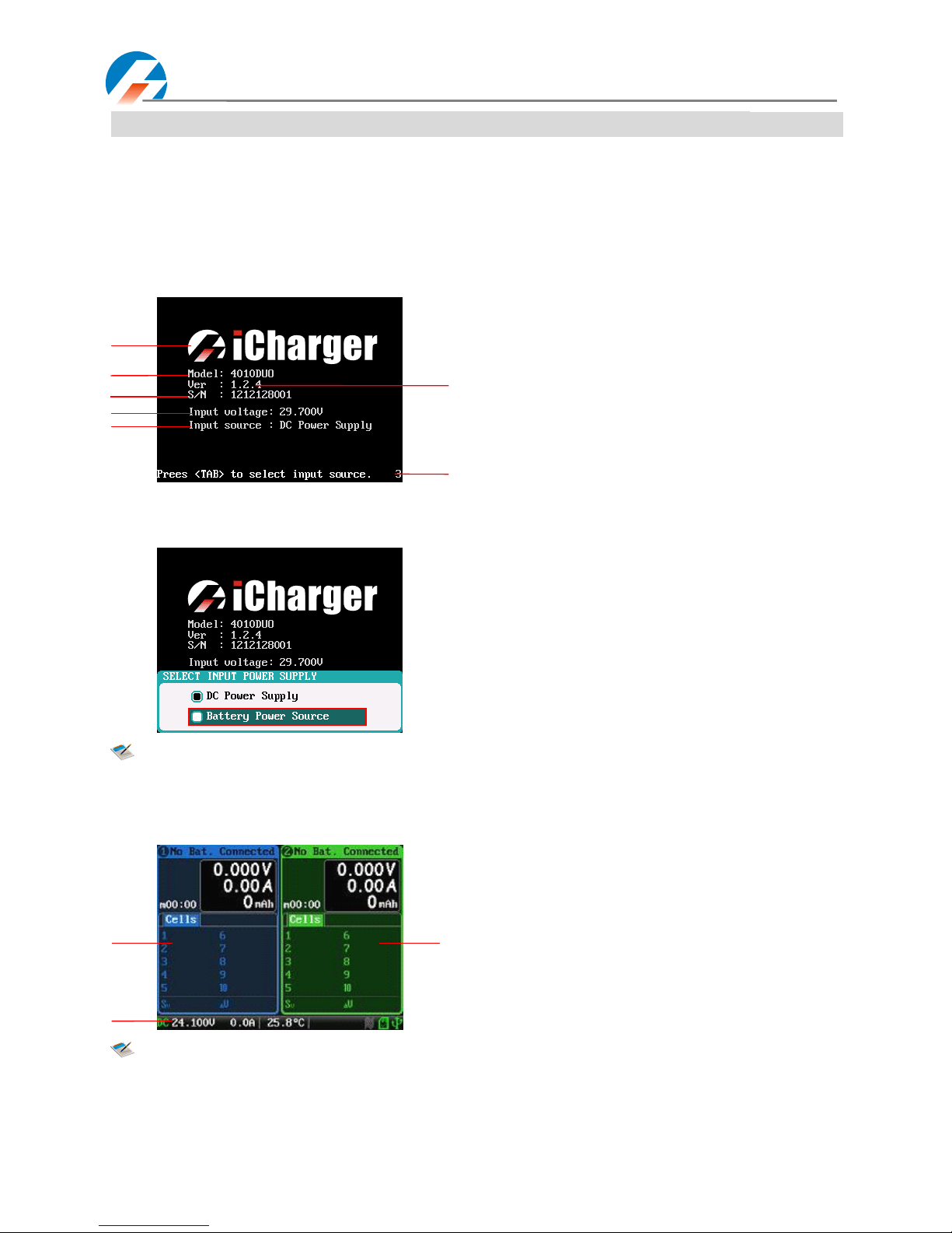
1. 4010DUO is a dual port charger, does not mean can charge/discharge for any configuration of the
two sets of batteries! Must follow: two battery packs have not any external electrical connection,
otherwise it will burn the charger or batteries. For example: charging 12S battery pack, must split
into two separate 6S, and absolutely prohibit to charg e with two 6S battery packs in series via
connecting with CH-1, CH-2 respectively.
2. 4010DUO input power cannot have fast fluctuations, which may cause output over current, and will
burn the charger or the batteries and input power in extreme cases. For example: setting the input
protection current and voltage is necessary according to the specifications of the input supply, in
order not to cause power overload. Some power overload protection will produce substantial
fluctuations for the voltage .
3. Keep the charger away from children and pets at all times.
4. Never leave the charger unsupervised when charging or discharging. If you leave, disconnect the battery to
prevent any unexpected dangers or damage.
5. Ensure the charger program and settings match the battery pack otherwise the battery will be damaged and a
dangerous situation may arise, especially for Lithium batteries, which may cause a fire.
6. Do not mix batteries of different types, different capacities or from different manufacturers.
7. Do not disassemble the charger.
8. Do not place the charger or any battery on a flammable surface or near a combustible material while in use. Do
not charge or discharge on a carpet, cluttered workbench, paper, plastic, vinyl, leather or wood, inside an R/C
model or inside a full-sized automobile.
9. Never block the air intake holes and never use in a refrigerated or high temperature environment. If used in such
an environment, the internal temperature protection may result in abnormal charging/discharging that could be
dangerous.
10. Do not allow water, moisture, metal wires or other conductive material into the charger.
11. Never charge or discharge any battery having evidence of leaking, expansion/swelling, damaged outer cover or
case, color-change or distortion.
12. Do not try to charge “ non-rechargeable ” dry cells.
13. Do not exceed the battery manufacturer
’
s suggested maximum charge rates.
14. Carefully follow the battery pack manufacturer
’
s recommendations and safety advice.
●
●
●
● Copyright
Copyright
Copyright
Copyright
Copyright@
Copyright@
Copyright@
Copyright@ Shenzhen
Shenzhen
Shenzhen
Shenzhen New
New
New
New Junsi
Junsi
Junsi
Junsi Electronic
Electronic
Electronic
Electronic Co.,
Co.,
Co.,
Co., Ltd.
Ltd.
Ltd.
Ltd. All
All
All
All rights
rights
rights
rights reserved.
reserved.
reserved.
reserved.
Without prior written consent by Shenzhen New Junsi Electronic Co., Ltd, any units or individual extract and copy
parts or entire contents of this manual, and transmission in any form is illegal and strictly prohibited.
The product described in this manual, may include copyright software ownership belonged to Shenzhen New Junsi
Electronic Co. Ltd and its licensee, except getting the permission from relevant rights holders, otherwise,
any copy, distribute, modify, excerpt, decompile, disassemble, decrypt, reverse engineering, lease, transfer, sub-license,
as well as other acts of infringement of software copyright is strictly prohibited, but apart from the restrictions
prohibited by applicable law.

iCharger
iCharger
iCharger
iCharger Synchronous
Synchronous
Synchronous
Synchronous Balance
Balance
Balance
Balance Charger/Discharger
Charger/Discharger
Charger/Discharger
Charger/Discharger 4010DUO
4010DUO
4010DUO
4010DUO
- 4 -
●
●
●
● 4010DUO
4010DUO
4010DUO
4010DUO Special
Special
Special
Special Features
Features
Features
Features
1. The 4010DUO uses advanced Synchronous buck-boost DC/DC converter technology , h igh power, and high current
and high-performance power conversion circuit. The maximum charge power capacity up to 2000W , the maximum
charge/discharge current of channel up to 40A, and two channels in Synchronous Mode up to 70A.
2. Channel S upport s 10s LiPo , Lilo , LiFe, with maximum 1.2A balance current, adopt s unique balance calculation of
internal resistance correct ion .
3. Intelligent fan control. Sensing internal temperature via the internal temperature sensor, to thereby control the fan
speed .
4. Internal temperature protection. When the internal temperature exceeds the reduce temperature, the output power is
automatically reduced; and the charger will shut down when temperature exceeds the cut- temperature.
5. 64 parameters sets can be saved, without repeat setting when use, just import/ export via SD card.
6. TFT LCD screen that provide s rich information including current, voltage, power, capacity, internal resistance,
control status, time-consuming and temperature, etc.
7. Multi-discharge features: discharge-self, regenerative to input discharge, regenerative to channel discharge, and
l ithium battery extra expanding discharge.
8. Support measurement for internal resistance of battery offline and online. Can measure not only the internal
resistance of the entire battery pack, but also measure the per-cell internal resistance of lithium battery.
9 . The iCharger has protection for reversed polarity (input or output), input voltage /current , battery temperature,
charging capacity , time overrun and maximum power etc .
10. Support s upgrading the hardware program by USB port. The iCharger also support s the “ L ogview ” software and
can display, plot and analyze the charge and discharge data by it. (See detail information about L ogview in the
following website: http://www.logview.info )
●Appearance
Appearance
Appearance
Appearance P
P
P
P arameters:
arameters:
arameters:
arameters:
● Net weight : 1.47kg
● Dimension : 210.0 × 140.1 × 80.2 ± 0.5mm
●Specifications
Specifications
Specifications
Specifications :
:
:
:
● Input voltage range : 9.0 — 50.0VDC
● Maximum input current limit: <65A
● Maximum charge/discharge current: 70A@Syn . Mode 40A@Asyn. Mode
● Maximum charge power capacity: 2000W (Channel 1400W @input > 23.5V)
● Maximum discharge power capacity: 200W (Channel 130W)
● Maximum regenerative discharge power capacity : 2000W (Channel 1400W)
● Maximum ext ra discharge power capacity: 3200W (Channel 1600W @40V/40A)
● Maximum c urrent drain for balancing: 2.4A@Syn . Mode 1.2A@Asyn. Mode

iCharger
iCharger
iCharger
iCharger Synchronous
Synchronous
Synchronous
Synchronous Balance
Balance
Balance
Balance Charger/Discharger
Charger/Discharger
Charger/Discharger
Charger/Discharger 4010DUO
4010DUO
4010DUO
4010DUO
- 5 -
Device
Device
Device
Device Introduction
Introduction
Introduction
Introduction
●
●
●
● 4010DUO
4010DUO
4010DUO
4010DUO Parts
Parts
Parts
Parts &
&
&
& Interface
Interface
Interface
Interface Introduction
Introduction
Introduction
Introduction
●
●
●
● 4010DUO
4010DUO
4010DUO
4010DUO Buttons
Buttons
Buttons
Buttons Function
Function
Function
Function &
&
&
& Icon
Icon
Icon
Icon s
s
s
s Description
Description
Description
Description
Part buttons allow to quick access to certain features when using 4010DUO, familiar with the icons on the interface
can understand better the working status of the charger, as shown in following chart:
Name
Name
Name
Name Function
Function
Function
Function s
s
s
s &
&
&
& Use
Use
Use
Use
KNOB
KNOB
KNOB
KNOB
Press: confirm
Counterclockwise rotation : up Clockwise rotation : down
Long press: pop up manage menu via long press on
BATTERY
MEMORY SELECTION
interface
exit the program after saving via long press on
BATTERY SETUP
interface
TAB/SYS
TAB/SYS
TAB/SYS
TAB/SYS
Long press: e nter
SYSTEM MENU
via long press on initial
interface , and r eturn to the previous menu via long
press on the rest interface
Click: can act as backspace when editing memory name on
MEMORY SETUP
, and return to the previous menu via
clicking on the rest interface
(
1
)
OUTPUT-1
﹣
(2)OUTPUT-1 ﹢
(3)TEMP-1
(4)BALANCE PORT-1
(5)BALANCE PORT-2
(6)TEMP-2
(7)OUTPUT-2 ﹢
(8)OUTPUT-2 ﹣
(9)LCD
(10 )STOP/START-1
(11 )STATUS-1
(12 )TAB/SYS
(13 )KNOB
(14 )STA TUS-2
(15 )STOP/START-2
(16 )J1,J2 PORT
(17 )USB
(18 )POWER OUTPUT LINE
(19 )FAN
(20 )BUZZER
(21 )SD CARD SLOT
19
17
20
21
15
16
13
14
12
11
9
10
54
2
7
1
8
3
6
18

iCharger
iCharger
iCharger
iCharger Synchronous
Synchronous
Synchronous
Synchronous Balance
Balance
Balance
Balance Charger/Discharger
Charger/Discharger
Charger/Discharger
Charger/Discharger 4010DUO
4010DUO
4010DUO
4010DUO
- 6 -
STATUS-1
STATUS-1
STATUS-1
STATUS-1
Long press: measure internal resistance of CH-1 via long press on
initial interface, and to pop up the parameters setup
interface via long press when running program
Click: switch to the information display of CH-1
STATUS-2
STATUS-2
STATUS-2
STATUS-2
Long press: measure internal resistance of CH-2 via long press on
the initial interface, and to pop up the parameters
setup interface via long press when running program
Click: switch to the information display of CH-2
STOP/START-1
STOP/START-1
STOP/START-1
STOP/START-1
Click: Click on the initial interface to enter
CH-1 - BATTERY
MEMORY SELECTION
, and click again to return the
initial interface
Long press: long press on the initial interface to enter the last
running program of
Run Program
on CH-1, and long
press again to run the selected program
STOP/START-2
STOP/START-2
STOP/START-2
STOP/START-2
Click: Click on the initial interface to enter
CH- 2- BATTERY
MEMORY SELECTION
, and click again to return the
initial interface
Long press: long press on the initial interface to enter the last
running program of
Run Program
on CH-2, and long
press again to run the selected program
STATUS-1+STOP/START
STATUS-1+STOP/START
STATUS-1+STOP/START
STATUS-1+STOP/START -1
-1
-1
-1
Press simultaneously on initial interface to enter
CH-1-MONITOR
SETTINGS
on CH- 1
STATUS-2+STOP/START
STATUS-2+STOP/START
STATUS-2+STOP/START
STATUS-2+STOP/START -2
-2
-2
-2
Press simultaneously on initial interface to enter
CH-2-MONITOR
SETTINGS
on CH- 2
STOP/START
STOP/START
STOP/START
STOP/START -1+STOP/START
-1+STOP/START
-1+STOP/START
-1+STOP/START -2
-2
-2
-2
Long press simultaneously on
Run Program
interface, two
channels will run the same program simultaneously
Fan status: a. Grey shows no running
b. Green shows running (the higher the green shows,
the faster the fan runs, and vice versa)
SD card status: a. Grey for the SD card is not inserted
b. Green for the SD card has been inserted and
can be used normally
USB status: a. Grey for not connecting USB
b. Green for has connected USB

iCharger
iCharger
iCharger
iCharger Synchronous
Synchronous
Synchronous
Synchronous Balance
Balance
Balance
Balance Charger/Discharger
Charger/Discharger
Charger/Discharger
Charger/Discharger 4010DUO
4010DUO
4010DUO
4010DUO
- 7 -
●
●
●
● 4010DUO
4010DUO
4010DUO
4010DUO Standard
Standard
Standard
Standard Accessories
Accessories
Accessories
Accessories
USB
USB
USB
USB data
data
data
data line
line
line
line #1
#1
#1
#1
700m
700m
700m
700m m
m
m
m
Power
Power
Power
Power cable
cable
cable
cable #1
#1
#1
#1
600m
600m
600m
600m m
m
m
m
Standard
Standard
Standard
Standard mini
mini
mini
mini USB
USB
USB
USB data
data
data
data line
line
line
line Power
Power
Power
Power input
input
input
input cable
cable
cable
cable
Balance
Balance
Balance
Balance c
c
c
c onnector
onnector
onnector
onnector c
c
c
c onversion
onversion
onversion
onversion b
b
b
b oard
oard
oard
oard #2
#2
#2
#2
70X44mm
70X44mm
70X44mm
70X44mm
Output
Output
Output
Output cable
cable
cable
cable #2
#2
#2
#2
320m
320m
320m
320m m
m
m
m
Suit
Suit
Suit
Suit for
for
for
for Align/Dualshy
Align/Dualshy
Align/Dualshy
Align/Dualshy battery
battery
battery
battery etc.
etc.
etc.
etc. Banana
Banana
Banana
Banana gold
gold
gold
gold plug
plug
plug
plug power
power
power
power output
output
output
output cable
cable
cable
cable (single
(single
(single
(single
channel)
channel)
channel)
channel) )
Balance
Balance
Balance
Balance wire
wire
wire
wire for
for
for
for b
b
b
b alance
alance
alance
alance board
board
board
board #2
#2
#2
#2
150
150
150
150 mm
mm
mm
mm
CD-ROM
CD-ROM
CD-ROM
CD-ROM #1
#1
#1
#1
Suit
Suit
Suit
Suit for
for
for
for Align/Dualshy
Align/Dualshy
Align/Dualshy
Align/Dualshy battery
battery
battery
battery etc.
etc.
etc.
etc. User
User
User
User
’
’
’
’
s
s
s
s manual
manual
manual
manual &
&
&
& Software
Software
Software
Software
●
●
●
● 4010DUO
4010DUO
4010DUO
4010DUO Optional
Optional
Optional
Optional Accessories
Accessories
Accessories
Accessories
Temperature
Temperature
Temperature
Temperature sensor
sensor
sensor
sensor lead
lead
lead
lead #2
#2
#2
#2
350m
350m
350m
350m m
m
m
m
Dual
Dual
Dual
Dual balance
balance
balance
balance wires
wires
wires
wires for
for
for
for balance
balance
balance
balance board
board
board
board #2
#2
#2
#2
15
15
15
15 0m
0m
0m
0m m
m
m
m
XP2.54
XP2.54
XP2.54
XP2.54 interface
interface
interface
interface temperature
temperature
temperature
temperature sensor
sensor
sensor
sensor lead
lead
lead
lead 11Pin-11Pin
11Pin-11Pin
11Pin-11Pin
11Pin-11Pin dual
dual
dual
dual balance
balance
balance
balance wire
wire
wire
wire
Dual
Dual
Dual
Dual channel
channel
channel
channel output
output
output
output cable
cable
cable
cable #1
#1
#1
#1
350m
350m
350m
350m m
m
m
m
Banana
Banana
Banana
Banana gold
gold
gold
gold plug
plug
plug
plug power
power
power
power output
output
output
output cable
cable
cable
cable (two
(two
(two
(two
channels)
channels)
channels)
channels)

iCharger
iCharger
iCharger
iCharger Synchronous
Synchronous
Synchronous
Synchronous Balance
Balance
Balance
Balance Charger/Discharger
Charger/Discharger
Charger/Discharger
Charger/Discharger 4010DUO
4010DUO
4010DUO
4010DUO
- 8 -
iCharger
iCharger
iCharger
iCharger Charge/Discharge
Charge/Discharge
Charge/Discharge
Charge/Discharge Setup
Setup
Setup
Setup &
&
&
& Use
Use
Use
Use
4010DUO iCharger can charge/discharge LiPo, Lilo, LiFe, NiHM, NiCd , Pb batteries, this manual divides into three
parts to introduce features and use for LiXX, NiXX, Pb batteries.
●
●
●
● Power
Power
Power
Power Supply
Supply
Supply
Supply Setup
Setup
Setup
Setup
The charger boots automatically when power on and the initial interface will display LOGO, charger relevant
information, power source and message etc.
System will delay
5S
5S
5S
5S
after booting, during this period, press
TAB
TAB
TAB
TAB /
/
/
/ SYS
SYS
SYS
SYS
button to change the input source type, while
press any other buttons to enter the initial interface.
Note : Set type of input power supply in
SYSTEM MENU →Charger Setup →Power Supply
; see details in
Page20 4010DUO
4010DUO
4010DUO
4010DUO Parameters
Parameters
Parameters
Parameters Setup
Setup
Setup
Setup .
After selecting the input power supply, confirm and enter the initial interface .
Note: The specific display of each region can refer to the introduction in Page10 & Page11 Program
Program
Program
Program
Running
Running
Running
Running Status
Status
Status
Status &Error
Error
Error
Error Messages
Messages
Messages
Messages .
Booting I nterface
1: Logo 2: Model
3: Version 4: Series number
5: Input power voltage
6: Input power source
7: Hint message
1
2
4
3
5
7
6
1
3
2
Initial I nterface
1: CH-1Channel I nfo rmation D isplay
2: CH-2Channel I nfo rmation D isplay
3: Status D isplay

iCharger
iCharger
iCharger
iCharger Synchronous
Synchronous
Synchronous
Synchronous Balance
Balance
Balance
Balance Charger/Discharger
Charger/Discharger
Charger/Discharger
Charger/Discharger 4010DUO
4010DUO
4010DUO
4010DUO
- 9 -
●
●
●
● Program
Program
Program
Program Add
Add
Add
Add &
&
&
& Manage
Manage
Manage
Manage
Click
STOP/START-
STOP/START-
STOP/START-
STOP/START- x
x
x
x
button on the initial interface to pop up the
BATTERY MEMORY SELECT
window .
4010DUO has 6 built-in programs before it enters to the market (shown in following picture) , which cannot be deleted
and limit for editing. The built-in program with underline is distinguished from the customized program by users.
Click " " ( or long press
KNOB
KNOB
KNOB
KNOB
)
)
)
)to pop up the
MANAGE
after exiting focus via pressing
TAB/SYS
TAB/SYS
TAB/SYS
TAB/SYS
, and click
" " to enter
MEMORY SETUP
to edit the program, and click " " to add new program
and enter its editing interface at the same time.
Note: If the program selected is a built-in program,
"Copy From
… " and "
Delete"
options are shown in
inactive status, and unable to be set.
●
●
●
● Run
Run
Run
Run Program
Program
Program
Program for
for
for
for Charger
Charger
Charger
Charger
After selecting program on
BATTERY MEMORY SELECTION ,
click to enter
Run Program
interface (long press
STOP/START-
STOP/START-
STOP/START-
STOP/START- x
x
x
x
button on the initial interface to enter
Run Program
of the last running program directly), as below:
Note:1. The built-in program is saved by default automatically to the running program, while the
program customized by users can set in
MEMORY SETUP →MEMORY OPTION →Auto save before
the program runs.
2. After setting the "capacity", the C-rate will appear behind the current, and when the C-rate
exceeds the certain value, the system will alarm beeps and warn (shown in following picture).
The specific value of battery is:LiXX battery :> 3C, NiXX battery :> 2C, Pb battery : > 0.3C
1: Run Program Selection
2: Common Pa rameter s S etup
3. Auto- save Hint
1
2
3

iCharger
iCharger
iCharger
iCharger Synchronous
Synchronous
Synchronous
Synchronous Balance
Balance
Balance
Balance Charger/Discharger
Charger/Discharger
Charger/Discharger
Charger/Discharger 4010DUO
4010DUO
4010DUO
4010DUO
- 10 -
A fter selecting the program to run , click confirmation to pop up
RUN PROGRAM
window, as below:
Click
Yes
Yes
Yes
Yes
to run the program , click
No
No
No
No
to cancel.
●
●
●
● Program
Program
Program
Program Running
Running
Running
Running Status
Status
Status
Status
Press
STATUS-x
STATUS-x
STATUS-x
STATUS-x
button when running program to switch to multipage information d isplay, as below:
32
1
2
1
1: Running program name 2: Battery type
3: Running channel status
4: Channel control status/external temperature
5: Running program time
6: Multipage information
7: Output voltage 8: Output current
9: Output capacity 10: Power source
11: Input voltage 12: Input current
13: Internal temperature 14: Fan status
15: SD card status 16: USB status
See d etails in Page34 Status
Status
Status
Status I
I
I
I ndication
ndication
ndication
ndication of
of
of
of R
R
R
R unning
unning
unning
unning
C
C
C
C hannel
hannel
hannel
hannel &Status
Status
Status
Status Indication
Indication
Indication
Indication of
of
of
of Channel
Channel
Channel
Channel Control
Control
Control
Control .
3
2
1
4
6
7
8
9
10
11
12
13
14
15
16
5
Cells voltage i nfo rmation
1: Cells voltage
2: Cells voltag e sum
3: Maximum cells v oltage
difference
4: Balance current indicat ion
IR information
1: Cell internal resistance
2: Pack internal resistance
3: Line resistance3

iCharger
iCharger
iCharger
iCharger Synchronous
Synchronous
Synchronous
Synchronous Balance
Balance
Balance
Balance Charger/Discharger
Charger/Discharger
Charger/Discharger
Charger/Discharger 4010DUO
4010DUO
4010DUO
4010DUO
- 11 -
Note: Different types of battery and program have different multipage information display, see detai ls
as below :
Press
STATUS-
STATUS-
STATUS-
STATUS- x
x
x
x
button for
2S
2S
2S
2S
when running program to pop up
MODIFY
interface , to modify the current , discharge
voltage, parameter s on line , as below :
Press
STOP
STOP
STOP
STOP /
/
/
/ START-x
START-x
START-x
START-x
button when running program to stop running , and press
STOP/START-x
STOP/START-x
STOP/START-x
STOP/START-x
button again to return
to the initial interface.
●
●
●
● Error
Error
Error
Error Message
Message
Message
Message s
s
s
s
When the 4010DUO is running, the system will stop the channel immediately and pop up the red dialog box and the
buzzer alarms if it detects an error, as below:
Types of battery Cells IR Info Cycle
LiXX √ √ √ √
NiXX × × √ √
Pb × × √ √
1
3
5
2
4
6
1
2
Information page
1: Power
2: End voltage
3:Lowest input voltage
4: Safety time
5: Temp. cutoff
6: End charge capacity
1
C ycle charge status
1: C ycle charge status
Error Messages Status
1: Error number
2: Error message
See all details in Page35 Error
Error
Error
Error Messages
Messages
Messages
Messages in
Appendix

iCharger
iCharger
iCharger
iCharger Synchronous
Synchronous
Synchronous
Synchronous Balance
Balance
Balance
Balance Charger/Discharger
Charger/Discharger
Charger/Discharger
Charger/Discharger 4010DUO
4010DUO
4010DUO
4010DUO
- 12 -
●
●
●
● Program
Program
Program
Program Edit
Edit
Edit
Edit
After adding new program or editing saved program, system will enter
MEMORY SETUP
interface, users can set or
modify the program on this interface .
Note:1.When editing program name, the character can be selected by turning
Knob
Knob
Knob
Knob
,
,
,
,and clicking the
Knob
Knob
Knob
Knob
to confirm the selected character, and clicking
TAB/SYS
TAB/SYS
TAB/SYS
TAB/SYS
button to delete the character;If
the program name is empty, the system will name automatically.
2.If the Editing program is the built-in program, program name and the types of battery
parameters cannot be changed.
After setting the basic parameters of battery, click " "to enter
MEMORY OPTION
interface , after setting click
“ ” to return
MEMORY SETUP
, and click “ ” to save.
Note: 1. Channel Mode has asynchronous, synchronous available, see more details in Page31
Important
Important
Important
Important Notes
Notes
Notes
Notes .
2. If select synchronous mode, the maximum current setting will change from 40A to 70A.
3. For built-in program, the
Auto save before the program runs
option is ticked by default.
■
■
■
■LiXX
LiXX
LiXX
LiXX Battery
Battery
Battery
Battery Charge/Discharge
Charge/Discharge
Charge/Discharge
Charge/Discharge Setup
Setup
Setup
Setup
After adding program, it will switch to LiXX battery in
Type
option on the
MEMORY SETUP
interface, and set the
number of
cells
and
capacity
, if not setting for the number of cells, the charger will set
A u to
by default , after editing
all parameters for program, click " " to save and return to the previous interface.
As shown in above picture, the program of Li Po, LiIo, LiFe battery has:
Charge, Storage, Discharge, Cycle and
Balance Only .
MEMORY SETUP Interface
1: Program name 2: Types of battery
3: Number of cells
4: Battery capacity 5: Available program
1
5
2
3
4
MEMORY OPTION Interface
Channel Mode: A synchronous ( default);
Synchronous
Run Counter: 0-999; default : 0
Log Interval: 0.5-60Sec; default : 1Sec

iCharger
iCharger
iCharger
iCharger Synchronous
Synchronous
Synchronous
Synchronous Balance
Balance
Balance
Balance Charger/Discharger
Charger/Discharger
Charger/Discharger
Charger/Discharger 4010DUO
4010DUO
4010DUO
4010DUO
- 13 -
①LiXX
LiXX
LiXX
LiXX Battery
Battery
Battery
Battery Charge
Charge
Charge
Charge Setup
Setup
Setup
Setup
Select
Program →Charg e
to enter
Charge
setup interface .
Note: 1.The charger first charges with constant current (CC) according to the user setting then turns
to constant voltage (CV) when the charging voltage reaches the peak point. In the CV phase
the current gradually falls, and the charger will terminate charging when the current falls
below than percent of the configured charge current.
2.Charge mode has
Balance, Not Balance
two modes available, when choose
Balance
mode,
balance board must be connected except for connecting 1S battery. The balance charge
mode is for balancing the voltage of battery cells while charging. In this mode the battery
balance lead must be connected to the balance port, and the charger can monitor the
voltage of individual cells and adjust the input current fed into each cell to normalize the
voltage.
3.Tick
Show
Show
Show
Show
to display this program on
MEMORY SETUP
, and the built-in program is ticked by
default.
4. When the value of charge cells voltage exceeds the recommended value (LiPo
4.2V,
LiIo
4.1V,
LiFe 3.6V), there will alarm and beep tones .As long as the users change the value, the main
charging interface, "battery types" and "cells voltage" setting value will displayed alternately.
Switch to
Balance
mode on
Chg Mode
to active " " button and click to enter
Balance
mode setup interface.
Switch to
User
mode on
Balance Speed
to active
Balance Diff , Balance Set Point , Balance Over Charge , Balance
Done Delay
setting , after setting click " " to return to the previous interface .
LiXX Battery Charge Program Setup
Chg Current:
0.05A-40A ; default : 2A
Chg Mode:
Balance (default), Not Balance
Chg End Current:
1%-50%; default : 10%
Chg Cell
Volt:
3.85V/Cell-4.35V/Cell ;
Default : 4.2V/Cell
LiXX Battery Balance S etup
Balance Start:
CV,
CV-0.1V--1V , Always
Default: CV -0.2 V
Balance Speed:
User , Fast ,
Normal (default ), Slow
LiXX Battery Charge Balance Setup
Balance Diff : 1mV-10mV ; default : 5mV
Balance Set Point: 1mV-50mV ; default : 5mV
Balance Over Charge : 0mV-10mV ; default : 0mV
Balance Done Delay : 0Min-20Min ; default : 1Min

iCharger
iCharger
iCharger
iCharger Synchronous
Synchronous
Synchronous
Synchronous Balance
Balance
Balance
Balance Charger/Discharger
Charger/Discharger
Charger/Discharger
Charger/Discharger 4010DUO
4010DUO
4010DUO
4010DUO
- 14 -
Note: If
Balance Diff
value is smaller , the voltage difference between batteries will be smaller and
time-consuming will be more when program ends.
If
Balance Set Point
value is smaller , the battery will be closer to the setting cut-off voltage and
time-consuming will be more when program ends.
Balance Over Charge
, the maximum overcharge compensation voltage acts as accelerated
charge, and the larger the value, the more obvious of accelerated charge.
For example: Charge Lipo with Vstd, set
Balance Over charge
to Vboc,the cells internal
resistance
detected is Ri, when the charge current is Ia, the actual CV value of cells is
Va
IF Ri*Ia > Vboc THEN
Va
= Vstd + Vboc
ELSE
Va
= Vstd+Ri*Ia
Please set this parameter after understanding fully, or keep the default value of 0. The value of
Balance Done Delay
is larger; the battery is closer to the setting cut-off voltage when program
ends.
Click " " to enter
LIXX ADVANCED SETUP
, after setting click " " to return to the previous interface.
Note:1.When the battery over-discharges, the charger will charge it with smaller current at the
beginning then turns to normal charging program when the battery voltage reaches the normal
value, otherwise the program will stop running.
2.After charging, the battery may not be completely filled; tick
Keep charging after the done
to
charge the battery with small er current when charging ends.
Click " " to enter
CHARGE SAFETY SETUP
, after setting click " " to return to the previous interface.
Note:
Cut-Temp.
is the maximum safety temperature of the battery and the program will stop running
when the temperature the sensor detected reaches this value, in order to protect the battery
from being damage by the high temperature.
LiXX B attery C harge Advanced Setup
Restore Lowest Voltage :
0.5V/Cell-2.5V/Cell ;
Default : 1V/Cell
Restore Charge Time :
1Min-5Min ; default : 3Min
Restore Charge Current :
0.02A-0.5A ; default : 0. 1 A
LiXX Battery Charge Safety Setup
Cut-Temp
:20 ℃-80 ℃; default : 45 ℃
Max Capacity:
50%-200%; default : 120 %
Safety Timer:
0Min-9999Min; default : off

iCharger
iCharger
iCharger
iCharger Synchronous
Synchronous
Synchronous
Synchronous Balance
Balance
Balance
Balance Charger/Discharger
Charger/Discharger
Charger/Discharger
Charger/Discharger 4010DUO
4010DUO
4010DUO
4010DUO
- 15 -
②LiXX
LiXX
LiXX
LiXX Battery
Battery
Battery
Battery Storage
Storage
Storage
Storage Setup
Setup
Setup
Setup
This mode is for storaging LiXX battery that is not to be used for an extended period. The charger determines whether
to charge or discharge the battery based on the configured target voltage. If the battery voltage exceeds the target
storage voltage it will start to discharge, while lower than the target storage voltage it will start to charge.
Select
Program →Storage
to enter
Storage
setup interface .
Note:1.
Accelerated storage:
accelerated storage via internal resistance correction. Tick
Accelerated
storage
to accelerated storage.
2 .
Storage Compensation
is the compensation for the battery voltage fallback: for storage charge,
the actual storage voltage=Storage Cell Voltage + Storage Compensation; for storage discharge,
the actual storage voltage=Storage Cell Voltage - Storage Compensation.
③LiXX
LiXX
LiXX
LiXX Battery
Battery
Battery
Battery Discharge
Discharge
Discharge
Discharge Setup
Setup
Setup
Setup
Select
Program →Discharge
to enter
Discharge
setup interface.
Note: 1.The charger first discharges with constant current (CC) according to the user setting then
turns to constant voltage (CV) when reaches the discharged voltage. In the CV phase the
current gradually falls, and the charger will terminate discharging when the current falls
below than percent of the configured discharge current.
For example: the default value of Discharge Current is 2A, the default value of End
Current is 50%: End Current=2A*50%=1A.
2. Regenerative mode has
OFF ,
To
input,
To
channel
three modes available, see more details
in Page32 Important
Important
Important
Important Notes
Notes
Notes
Notes .
When switch to
To
channel
on
Regenerative Mode
, “ " button changes to the operational state, click to enter
To
channel
setup interface , after setting click " " to return to the previous interface.
Note: This setting is mainly in charge of controlling the regenerative voltage and current, to prevent the
charger from being damaged by regenerative charge.
Storage Cell V oltage
:3.7V/Cell-3.9V/Cell ;
Default : 3.85V/Cell
Storage Compensation
:0V/Cell-0.2V/Cell;
Default : 0. 01 V/Cell
LiXX B attery Discharge setup
Discharge Current :
0.05A-40A ; default : 2A
Discharge V oltage
:3V/Cell-4.1V/Cell ;
Default : 3.5V/Cell
End Current
:1%-100% ; default : 50%
Regenerative Mod e:
OFF (default),
To
input,
To
channel
LiXX
LiXX
LiXX
LiXX Battery
Battery
Battery
Battery Channel
Channel
Channel
Channel Regenerative
Regenerative
Regenerative
Regenerative Setup
Setup
Setup
Setup
Channel Joi n:
Not available
Voltage Limit :
0.1V-40V ; default : 12V
Current Limit :
0.05A-40A ; default : 1A

iCharger
iCharger
iCharger
iCharger Synchronous
Synchronous
Synchronous
Synchronous Balance
Balance
Balance
Balance Charger/Discharger
Charger/Discharger
Charger/Discharger
Charger/Discharger 4010DUO
4010DUO
4010DUO
4010DUO
- 16 -
Click " " to enter
LiXX DISCHARGE ADVANCED SETUP
interface, after setting click " " to return to
the previous interface.
Note: 1.Tick
Extra Discharge Enable
to active extra discharge enable, see more details in Page33
Extra
Extra
Extra
Extra Discharge
Discharge
Discharge
Discharge .
2. Tick
Balance enable
to active balance discharge; when discharge enters the CV phase, it
starts to balance for the cell voltages.
Click " " to enter
DISCHARGE SAFETY SETUP
interface, see details about setting in Page13 LiXX
LiXX
LiXX
LiXX Battery
Battery
Battery
Battery
C
C
C
C harge
harge
harge
harge S
S
S
S etup
etup
etup
etup .
④LiXX
LiXX
LiXX
LiXX Battery
Battery
Battery
Battery Cycle
Cycle
Cycle
Cycle Setup
Setup
Setup
Setup
Select
Program →Cycle
to e nter
Cycle
setup interface, after setting click " " to return to the previous interface .
⑤LiXX
LiXX
LiXX
LiXX Battery
Battery
Battery
Battery Only
Only
Only
Only Balance
Balance
Balance
Balance Feature
Feature
Feature
Feature
Select
Program →Balance Only
to e nter
Balance Only
setup interface, after setting click " " to return to the
previous interface.
Note:
Only Bal
is the program to perform balance feature, cannot charge/discharge the Battery.
LiXX Battery Cycle Setup
Cycle Mode
:CHG → DCHG (default);
DCHG → CHG
Cycle Count :
1-99; default : 3
Delay Time :
0Min-9999Min; default : 3Min

iCharger
iCharger
iCharger
iCharger Synchronous
Synchronous
Synchronous
Synchronous Balance
Balance
Balance
Balance Charger/Discharger
Charger/Discharger
Charger/Discharger
Charger/Discharger 4010DUO
4010DUO
4010DUO
4010DUO
- 17 -
■
■
■
■NiXX
NiXX
NiXX
NiXX Battery
Battery
Battery
Battery Charge/Discharge
Charge/Discharge
Charge/Discharge
Charge/Discharge Setup
Setup
Setup
Setup
After adding program, it will switch to NiXX battery in
Type
option on the
MEMORY SETUP
interface, and set the
capacity, the number of cells for NiXX battery cannot be set , and the charger sets
Auto
by default , after editing all
parameters for program, click " " to save and return to the previous interface.
As shown in above picture, the program of NiMH , NiCd have:
Charge, Discharge
and
Cycle
.
①NiXX
NiXX
NiXX
NiXX Battery
Battery
Battery
Battery Charge
Charge
Charge
Charge Setup
Setup
Setup
Setup
Select
Program →Charge to
enter
Charge
setup interface.
Note: Charge Mode has
Normal , Reflex
two modes available; use the reflex mode to charge battery
can reduce heat of battery; please see charging principle in Page32 Important
Important
Important
Important Notes
Notes
Notes
Notes .
.
.
.
Click " " to enter
NiXX CHARGE OPTION SETUP
interface, after setting click " " to return to the
previous interface.
Note: Tick
Allow 0V Charging
to allow charge with
0V.
Allow 0V Charging
suits for some applications (such as charge the battery pack in the
transmitter, the circuit in series with a diode).
Tick
Trickle Enable →Enable
to active trickle charge and set the parameters, after setting click " " to return to the
previous interface.
Note: Tick
Enable
to active trickle charge.
Trickle charge is based on a smaller current to charge the battery for a period, to reduce
battery consumption and extend battery usage time.
NiXX B attery Charge Setup
Chg Current :
0.05A-40A ; default : 2A
Chg Mode :
Normal (default) , Reflex
NiXX Battery C harge Advanced Setup
Sensitivity :
1mV-20mV; default : 3mV
Delay time :
0Min-20Min ; default : 3Min
NiXX Battery Trickle Charge Setup
Trickle current :
0. 0 2A-1A ; default : 0. 0 5A
Trickle timeout :
1Min-999Min;
default : 5Min

iCharger
iCharger
iCharger
iCharger Synchronous
Synchronous
Synchronous
Synchronous Balance
Balance
Balance
Balance Charger/Discharger
Charger/Discharger
Charger/Discharger
Charger/Discharger 4010DUO
4010DUO
4010DUO
4010DUO
- 18 -
Click " " to enter
CHARGE SAFETY SETU
interface, see details about setting in Page13 L
L
L
L iXX
iXX
iXX
iXX Battery
Battery
Battery
Battery C
C
C
C harge
harge
harge
harge
S
S
S
S etup
etup
etup
etup .
②NiXX
NiXX
NiXX
NiXX Battery
Battery
Battery
Battery Discharge
Discharge
Discharge
Discharge Setup
Setup
Setup
Setup
Select
Program →Discharge
to enter
Discharge
setup interface .
Note: 1. Regenerative mode has
OFF ,
To
input,
To
channel
three modes available, see more details in
Page33 Important
Important
Important
Important Notes
Notes
Notes
Notes .
2
.
To
channel
Setup please see Page12 LiXX
LiXX
LiXX
LiXX Charge/Discharge
Charge/Discharge
Charge/Discharge
Charge/Discharge Setup
Setup
Setup
Setup .
Click " " to enter
DISCHARGE SAFETY SETUP
interface, see details about setting in Page13 L
L
L
L iXX
iXX
iXX
iXX B
B
B
B attery
attery
attery
attery
C
C
C
C harge
harge
harge
harge S
S
S
S etup
etup
etup
etup .
③NiXX
NiXX
NiXX
NiXX Battery
Battery
Battery
Battery Cycle
Cycle
Cycle
Cycle Setup
Setup
Setup
Setup
Select
Program →Cycle to
enter
Cycle
setup interface, see details about setting in Page16 LiXX
LiXX
LiXX
LiXX B
B
B
B attery
attery
attery
attery Cycle
Cycle
Cycle
Cycle S
S
S
S etup
etup
etup
etup .
LiXX Battery Discharge Setup
Discharge Current :
0.05A-40A ; default : 2A
Discharge Voltag e
:0.1V-40V ; default : 0.1V
End Current :
1%-100% ; default : 50%
Regenerative Mode
:OFF (default) ,
To
input,
To
channel
l s

iCharger
iCharger
iCharger
iCharger Synchronous
Synchronous
Synchronous
Synchronous Balance
Balance
Balance
Balance Charger/Discharger
Charger/Discharger
Charger/Discharger
Charger/Discharger 4010DUO
4010DUO
4010DUO
4010DUO
- 19 -
■
■
■
■Pb
Pb
Pb
Pb Battery
Battery
Battery
Battery Charge/Discharge
Charge/Discharge
Charge/Discharge
Charge/Discharge Setup
Setup
Setup
Setup
After adding program, it will switch to Pb battery in
Type
option on the
MEMORY SETUP
interface, and set the
number of
cells
and
capacity
, after editing all parameters for program, click " " to save and return to the previous
interface.
As shown in above picture, the program of Pb battery has:
Charge, Discharge and Cycle .
①Pb
Pb
Pb
Pb Battery
Battery
Battery
Battery Charge
Charge
Charge
Charge Setup
Setup
Setup
Setup
Select
Program →Charge
to enter
Charge
setup interface.
Note: 1.The charger first charges with constant current (CC) according to the user setting then turns
to constant voltage (CV) when the charging voltage reaches the peak point. In the CV phase
the current gradually falls, and the charger will terminate charging when the current falls
below than percent of the configured charge current.
2.Charge mode has
Normal, Reflex
two modes available, about the
Reflex
mode (Reflex) please
see Page32 Important
Important
Important
Important Notes
Notes
Notes
Notes ;
;
;
;
Click " " to enter
PB ADVANCED SETUP
interface, see details about setting in Page13 LiXX
LiXX
LiXX
LiXX B
B
B
B attery
attery
attery
attery
C
C
C
C harge
harge
harge
harge S
S
S
S etup
etup
etup
etup .
Click " " to enter
CHARGE SAFETY SETUP
interface, see details about setting in Page13 LiXX
LiXX
LiXX
LiXX B
B
B
B attery
attery
attery
attery
C
C
C
C harge
harge
harge
harge S
S
S
S etup
etup
etup
etup .
②Pb
Pb
Pb
Pb Battery
Battery
Battery
Battery Discharge
Discharge
Discharge
Discharge Setup
Setup
Setup
Setup
Select
Program →Discharge to
enter
Discharge
setup interface, see details about setting in Page15 LiXX
LiXX
LiXX
LiXX B
B
B
B attery
attery
attery
attery
Discharge
Discharge
Discharge
Discharge S
S
S
S etup
etup
etup
etup .
③Pb
Pb
Pb
Pb Battery
Battery
Battery
Battery Cycle
Cycle
Cycle
Cycle Setup
Setup
Setup
Setup
Select
Program →Cycle
to enter
Cycle
setup interface, see details about setting in Page16 LiXX
LiXX
LiXX
LiXX B
B
B
B attery
attery
attery
attery Cycle
Cycle
Cycle
Cycle S
S
S
S etup
etup
etup
etup .
LiXX Battery Charge Setup
Chg Current :
0.05A-40A ; default : 2A
Chg Mode :
Normal (default) , Reflex
Chg End Current :
1%-50%; default : 10%
Chg Cell
Volt
:
2 V/Cell- 2.6 V/Cell ;
Default : 2.4 V/Cell

iCharger
iCharger
iCharger
iCharger Synchronous
Synchronous
Synchronous
Synchronous Balance
Balance
Balance
Balance Charger/Discharger
Charger/Discharger
Charger/Discharger
Charger/Discharger 4010DUO
4010DUO
4010DUO
4010DUO
- 20 -
4010DUO
4010DUO
4010DUO
4010DUO Parameter
Parameter
Parameter
Parameter s
s
s
s Setup
Setup
Setup
Setup
●
●
●
● 4010DUO
4010DUO
4010DUO
4010DUO Parameter
Parameter
Parameter
Parameter s
s
s
s Setup
Setup
Setup
Setup
Press
TAB/SYS
TAB/SYS
TAB/SYS
TAB/SYS
button for
2S
2S
2S
2S
on the initial interface to enter
SYSTEM MENU
interface, set ting and test ing of the
system parameter s , storage and servo can be completed on this interface.
■
■
■
■Charger
Charger
Charger
Charger Setup
Setup
Setup
Setup
After setting all parameters, click “ ” to save and return to the previous interface.
①Temp.
Temp.
Temp.
Temp. &
&
&
& Fans
Fans
Fans
Fans Setup
Setup
Setup
Setup
Select
SYSTEM MENU →Charger Setup →Temperature&Fans to
enter the setup interface, after setting click “ ” to
save and return to the previous interface.
Note:
When the charger internal temperature reaches to the
ON Temperature
, the fan will boot
automatically to dissipate heat, and adjust speed automatically depends on the temperature
increasing or decreasing. When the temp. exceeds (
Shut Down – Power Reduce
), the charger will
stop increasing(temp. shown in orange) via reducing the largest power limit. When the
temp.reaches (Shut Down) temperature, the charger will shut down. [ when temp. > (Shut Down-3 ) ,
the temp. shown in red flashing ]
.
When the temp. is lower than the
ON Temperature
, the fan will
keep running within the setting time of OFF Delay Time.
1 : Charger Setup M enu
2: Temp. & Fans Setup 3: Beep
T
one S etup
4: LCD S etup 5: Output P ower S etup
6: Power S upply S etup
7: Save & Load Configuration S etup
8: Calibration
9 : Extra- Function
10: Log F iles M anage 11: Servo Test
12: Pulse Test
1 : Temperature setup
Unit :
Celsius (default), Fahrenheit
Shut Down :
60 ℃-75 ℃; default : 75 ℃
Power Reduce :
5℃-20 ℃;default:10 ℃
2 : Cooling Fans setup
ON Temperature :
30 ℃-50 ℃;default:40 ℃
OFF Delay Time :
0Min-10Min;default:2Min
1
2
12
11
10
9
8
7
6
5
3
2
1
4
Other manuals for 4010DUO
2
Table of contents
Other iCharger Batteries Charger manuals

iCharger
iCharger 1010B User manual

iCharger
iCharger 106B+ User manual

iCharger
iCharger 456DUO User manual

iCharger
iCharger 3010B User manual

iCharger
iCharger 4010DUO User manual

iCharger
iCharger 4010DUO User manual

iCharger
iCharger 458DUO User manual

iCharger
iCharger Battery Charger User manual

iCharger
iCharger DX8 User manual

iCharger
iCharger 308DUO User manual