5
WARNINGS continued
Hazardous fluid or toxic fumes can cause serious in-
jury or death if splashed in eyes or on skin, inhaled or
swallowed. Know the hazards of the fluid you are us-
ing. Store & dispose of hazardous fluids according
to manufacturer, local, state & national guidelines.
ALWAYS wear protective eyewear, gloves, clothing
and respirator as recommended by fluid manufacturer.
TOXIC FLUID HAZARD
HIGH PRESSURE SPRAY CAN CAUSE EXTREMELY SERIOUS INJURY. Handle as you would a
loaded firearm. Follow PRESSURE RELIEF PROCEDURE on page 6. Observe all warnings.
MEDICAL ALERT -Airless Spray Wounds
If any fluid appears to penetrate your skin, get
EMERGENCY MEDICAL CARE AT ONCE.
DO NOT TREAT AS A SIMPLE CUT.
Tell the doctor exactly what fluid was injected.
NOTE TO PHYSICIAN: Injection in the skin is a trau-
matic injury. It is important to treat the injury surgi-
cally as soon as possible. DO NOT DELAY treat-
menttoresearchtoxicity.Toxicity is a concern with some
exotic coatings injected directly into the blood stream. Con-
sultation with a plastic surgeon or reconstructive hand sur-
geon may be advisable.
GENERAL PRECAUTIONS
NEVER alter equipment in any manner.
NEVER smoke while in spraying area.
NEVER spray highly flammable materials.
NEVER use around children.
NEVER allow another person to use sprayer unless
he is thoroughly instructed on its' safe use and given
this operators manual to read.
ALWAYS wear a spray mask, gloves and protective
eye wear while spraying.
ALWAYS ensure fire extinquishing equipment is
readily available and properly maintained.
NEVER LEAVE SPRAYER UNATTENDED WITH PRES-
SURE IN THE SYSTEM. FOLLOW PRESSURE RELIEF
PROCEDURES ON PAGE 6.
Fluids under high pressure from spray or leaks can
penetrate the skin and cause extremely serious
injury, including the need for amputation.
NEVER
point the spray gun at anyone or any part of
the body.
NEVER
put hand or fingers over the spray tip. Do not
use rag or other materials over your fingers. Paint will
penetrate through these materials and into the hand.
NEVER
try to stop or deflect leaks with your hand or
body.
ALWAYS
have gun tip guard in place when spraying.
ALWAYS lock gun trigger when you stop spraying.
ALWAYS remove tip from the gun to clean it.
NEVER try to "blow back" paint, this is not an air spray
sprayer.
ALWAYS follow the PRESSURE RELIEF PROCE-
DURE, as shown on page 6, before cleaning or remov-
ing the spray tip or servicing any system equipment.
Be sure equipment safety devices are operating prop-
erly before each use.
Tighten all fluid connections before each use.
MEDICAL TREATMENT
If any fluid appears to penetrate your skin, get EMER-
GENCY CARE AT ONCE. DO NOT TREAT AS A
SIMPLE CUT.
* Go to an emergency room immediately.
* Tell the doctor you suspect an injection injury.
* Tell him what kind of material you were spraying with
and have him read NOTE TO PHYSICIAN above.
INJECTION HAZARD ALWAYS INSPECT SPRAYING AREA
Keep spraying area free from obstructions.
Make sure area has good ventilation to safely remove
vapors and mists.
NEVER keep flammable material in spraying area.
NEVER spray in vicinity of open flame or other
sources of ignition.
Spraying area must be at least 20 ft. away from spray
unit.
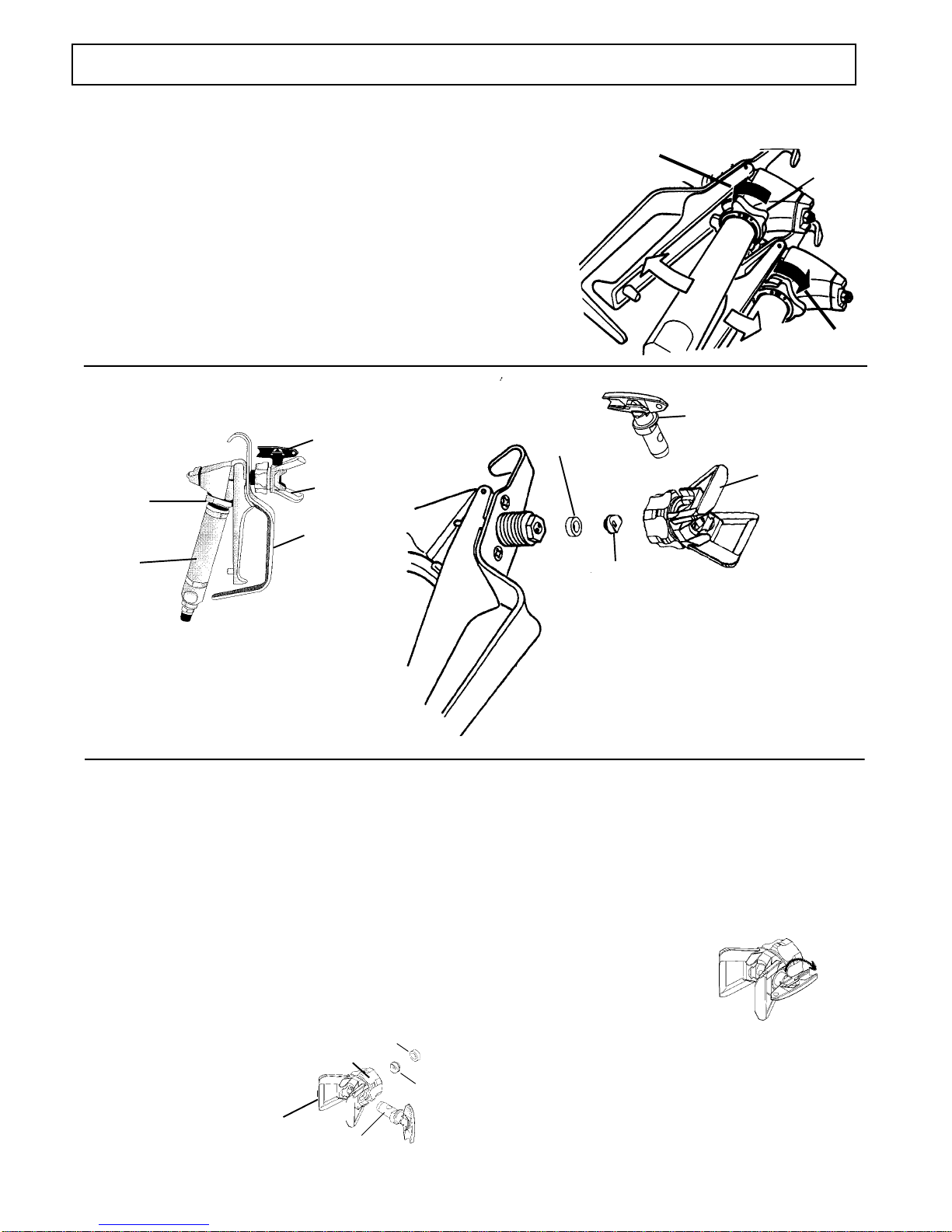
SPRAY GUN SAFETY
ALWAYS set safety lock on the gun in "LOCKED" posi-
tion when not in use and before servicing or cleaning.
DO NOT remove or modify any part of gun.
ALWAYS REMOVE SPRAY TIP when cleaning. Flush
unit with LOWEST POSSIBLE PRESSURE.
CHECK operation of all gun safety devices before each
use.
Be very careful when removing the spray tip or hose
from gun. A plugged line contains fluid under pressure.
If the tip or line is plugged, follow thePRESSURE RE-
LIEF PROCEDURE as outlined on page 6.
TIP GUARD
ALWAYS have the tip guard in place on the spray gun
while spraying. The tip guard alerts you to the injection
hazard and helps prevent accidentally placing your fin-
gers or any part of your body close to the spray tip.
SPRAY TIP SAFETY
Use extreme caution when cleaning or changing spray
tips. If the spray tip clogs while spraying, engage the
gun safety latch immediately. ALWAYS follow the
PRESSURE RELIEF PROCEDURE and then remove
the spray tip to clean it.
NEVER wipe off build up around the spray tip.
ALWAYS remove tip & tip guard to clean AFTER
pump is turned off and the pressure is relieved by fol-
lowing the PRESSURE RELIEF PROCEDURE.