manuals.online logo
Brands
  1. Home
  2. •
  3. Brands
  4. •
  5. ICM Controls
  6. •
  7. Controllers
  8. •
  9. ICM Controls ICM330 User manual

ICM Controls ICM330 User manual

Other ICM Controls Controllers manuals

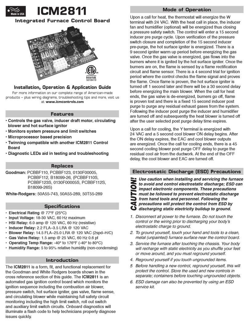
ICM Controls ICM2811 General instructions

ICM Controls

ICM Controls ICM2811 General instructions

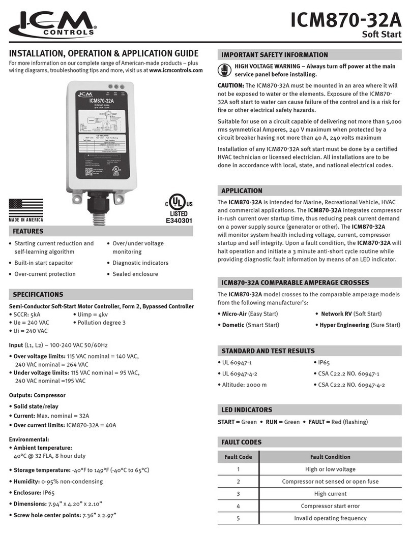
ICM Controls ICM870-32A General instructions

ICM Controls

ICM Controls ICM870-32A General instructions

ICM Controls ICM271 General instructions

ICM Controls

ICM Controls ICM271 General instructions

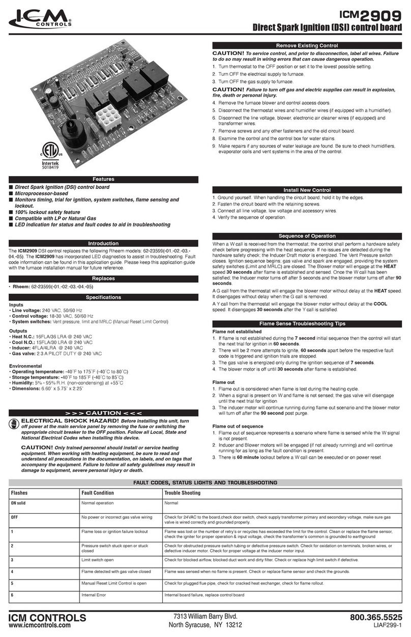
ICM Controls ICM2909 User manual

ICM Controls

ICM Controls ICM2909 User manual

ICM Controls ICM2812ж ICM2812-KIT General instructions

ICM Controls

ICM Controls ICM2812ж ICM2812-KIT General instructions

ICM Controls ICM325HNV General instructions

ICM Controls

ICM Controls ICM325HNV General instructions

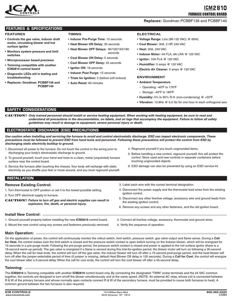
ICM Controls ICM2810 User manual

ICM Controls

ICM Controls ICM2810 User manual

ICM Controls ICM550 User manual

ICM Controls

ICM Controls ICM550 User manual

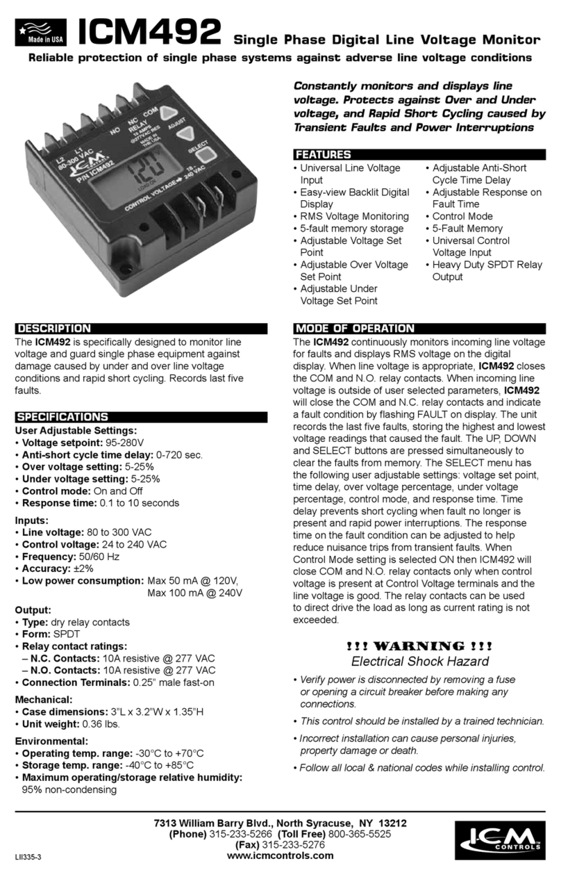
ICM Controls ICM492 User manual

ICM Controls

ICM Controls ICM492 User manual

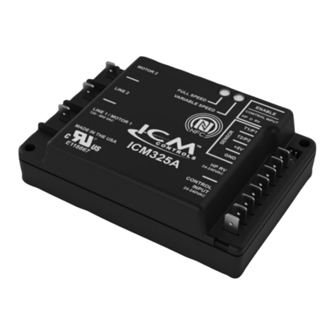
ICM Controls ICM325A General instructions

ICM Controls

ICM Controls ICM325A General instructions

ICM Controls ICM1511 Series User manual

ICM Controls

ICM Controls ICM1511 Series User manual

ICM Controls ICM2909 User manual

ICM Controls

ICM Controls ICM2909 User manual

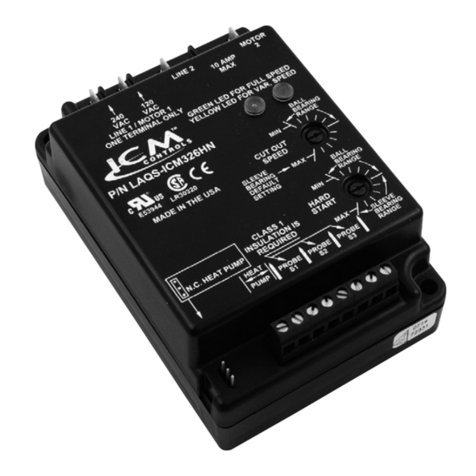
ICM Controls ICM326HN Manual

ICM Controls

ICM Controls ICM326HN Manual

ICM Controls ICM325A General instructions

ICM Controls

ICM Controls ICM325A General instructions

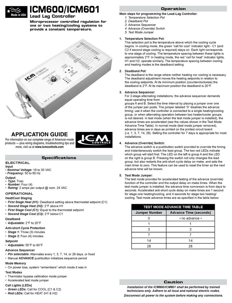
ICM Controls ICM600 User guide

ICM Controls

ICM Controls ICM600 User guide

ICM Controls ICM271 User manual

ICM Controls

ICM Controls ICM271 User manual

Popular Controllers manuals by other brands

Sunricher SR-ZV9003T3-RGBW-US Installation

Sunricher

Sunricher SR-ZV9003T3-RGBW-US Installation

Ksenia intro Installation and configuration manual

Ksenia

Ksenia intro Installation and configuration manual

Inovance CAN200 Series manual

Inovance

Inovance CAN200 Series manual

Gauzy LC6 FLEX Controller Installation and operation guide

Gauzy

Gauzy LC6 FLEX Controller Installation and operation guide

Viking SLP-1 Technical practice

Viking

Viking SLP-1 Technical practice

CKD KBX-30E-U Series instruction manual

CKD

CKD KBX-30E-U Series instruction manual

Sharp Energy Sun Flux User manual & installation guide

Sharp Energy

Sharp Energy Sun Flux User manual & installation guide

Yamaha RCX40 user manual

Yamaha

Yamaha RCX40 user manual

AB Quality PowerFlex 400 Frames D-H Service bulletin

AB Quality

AB Quality PowerFlex 400 Frames D-H Service bulletin

Yamaha MJC8 owner's manual

Yamaha

Yamaha MJC8 owner's manual

AL-KO ATC operating instructions

AL-KO

AL-KO ATC operating instructions

Savant SmartControl 2 Deployment guide

Savant

Savant SmartControl 2 Deployment guide

GameSir T3S user manual

GameSir

GameSir T3S user manual

Kostal inveor operating manual

Kostal

Kostal inveor operating manual

Emerson Yarway 20-55 Operating and safety instructions

Emerson

Emerson Yarway 20-55 Operating and safety instructions

CoCo ACM-LV24 Quick installation guide

CoCo

CoCo ACM-LV24 Quick installation guide

Brooks SLA5810/20 Installation and operation manual

Brooks

Brooks SLA5810/20 Installation and operation manual

SIGMA TEK SR 011 Technical manual

SIGMA TEK

SIGMA TEK SR 011 Technical manual

manuals.online logo
manuals.online logoBrands
  • About & Mission
  • Contact us
  • Privacy Policy
  • Terms and Conditions

Copyright 2025 Manuals.Online. All Rights Reserved.

Installation, Operation &
Application Guide
For more information on our complete
range of American-made products – plus
wiring diagrams, troubleshooting tips and
more, visit us at www.icmcontrols.com
Installation of the ICM330 shall be performed by trained technicians only. Adhere to all local and
national electric codes.
Disconnect all power to the system before making any connections.
Caution!
• Line voltage:120,208,240,277,and480VAC
• Control voltage:18-30VAC
• Current:4ampsmaximum
• Frequency:50-60Hz
• Operating temperature:-40ºFto+176ºF(-40°Cto+75°C)
• Probes:
–Temperature:Thermistor,10Kohmat77°F(25°C)
–Pressure:ICM380(orderedseparately)
• Heat pump override:24VACN.C.orN.O.
• Weight:12ounces(341grams)
Note:TheICM330shouldbeappliedtomotorsandequipmentthathavebeendesignatedbytheir
respectivemanufacturersascapableofbeingspeedcontrolled.
• Mounting:
 – Surfacemountusing(2)#8screws
 – ItisrecommendedthattheICM330bemountedawayfromthecondenserexhaustairinorderto
maintainloweroperatingtemperatures
Specifications
ICM330
Head Pressure Control with
Optional Heat Pump Override
Regulates head pressure via temperature or pressure input
Connections for ICM330 at 120/208/240/277 VAC
1. Removepowerfromsystem.
2. FieldinstallawirefromLine 1wireto120/280 VACterminal.
3. CutLine 2wire;afxmotorsidetoMotor 2terminalandlinesidetoLine 2terminal.
4. Make24VAC,probeandHPconnections.
5. Verifywiringiscorrect.
6. Powerupsystemandcheckoperation.
FieldInstalledWire
1. Removepowerfromsystem.
2. FieldinstallawirefromLine 1wireto480 VACterminal.
3. CutLine 2wire;afxmotorsidetoMotor 2terminalandlinesidetoLine 2terminal.
4. Make24VAC,probeandHPconnections.
5. Verifywiringiscorrect.
6. Powerupsystemandcheckoperation.
Connections for ICM330 at 480 VAC
Field
Installed
Wire
Connections for Heat Pump System at 480 VAC
1.Removepowerfromsystem.
2.FieldinstallawirefromLine 1wireto480 VACterminal.
3.CutLine 2wire;afxthecommonfromthedefrost
board’sfanrelaytotheMotor 2terminalandtheLine
fromthecontactortotheLine 2terminal.
4.Make24VAC,probeandHPconnections.
5.Verifywiringiscorrect.
6.Powerupsystemandcheckoperation.
Connections for Heat Pump System at 120/208/240/277 VAC
1.Removepowerfromsystem.
2.FieldinstallawirefromLINE 1wireto120/280VACterminal.
3.CutLine 2wire;afxthecommonfromthedefrostboard’s
fanrelaytotheMotor 2terminalandtheLinefromthe
contactortotheLine 2terminal.
4.Make24VAC,probeandHPconnections.
5.Verifywiringiscorrect.
6.Powerupsystemandcheckoperation.
Example
1.Onlyoneprobetypecanbeusedatatime,temperatureORpressure.
2.AtypicalinstallationisshowninAppendixsection.Thetemperatureprobecan
beattachedtotheU-bend.Usetheprovidedthermo-tapetosecuretheprobe
totheplaceofattachment.
3.Whenusingapressureprobe,installitonthedischargelinetransducertting.
4.AtemperatureorpressureprobeisconnectedtoICM330asshowninthe
respectivewiringdiagrambelow.
Installing and Connecting the Probe
TemperatureProbe
BLUEWHITEGREENREDBLACK
PRESSURE TRANSDUCER
Field Installed Wire
PSC
Fan
Motor
Run
Capacitor
Fan
Relay
COM NC
Defrost Board
Field Installed Wire
PSC
Fan
Motor
Run
Capacitor
Fan
Relay
COM NC
Defrost Board
1.For non-heat pump applications,theheatpumpselectjumpermustbeintheDefault(N.O.)
position,andtheHPterminalsmustbeleftunconnected.
2.SettheCutoutSpeedandtheHardStartTimetotheappropriatepositionsforthetypeofmotoryou
have(seebelow).
Connections for Air Conditioning Only
Mode of Operations
Whenusingatemperatureprobe,thecontrolwillmaintaincondensertemperaturebetween7°Fabove
and7°FbelowdialedTemperatureSetpoint.ThedialTemperatureSetpointrangeis70°Fto140°F.
Whenusingapressureprobe,thecontrolwillmaintaincondenserpressurebetween20psigaboveand
20psigbelowdialedPressureSetpoint.ThedialPressureSetpointrangeis35psigto465psig.
Theisnocorrelationbetweendialtemperatureandpressurescalesonthecontrol.
Whenthemotorstartsrunningitwillhard startforthelengthoftimedictatedbythehard startdial
setting.Afterthehard starttimehaselapsed,themotorspeediscontrolledbytheprobereading,
temperatureorpressure.Thegreenlightturnsonwhenthemotorrunsatfullspeed.
Asthesensedtemperature/pressuredecreases,theoutputvoltagedecreases.Theyellowlightturnson
duringmotorvariablespeed.Theoutputvoltagemaydecreasetotheminimumvoltagedictatedbythe
cutout speeddial.Astemperature/pressuredecreasesfurther,theoutputvoltagegoestozerovolts.
Theyellowlightturnsoff.
Thecutoutspeeddialadjuststhemotorvoltagerange.Setthecutout
voltagedialaccordingtothetypeofmotoryouhave.
Sleeve Bearing Motors: Setthecutoutspeeddialtothemiddleof
thesleevebearingrange.Inthisrange,
themotorcanrundownapproximately40-
50%ofthefulllinevoltage,whichallows
sufcientRPMsforcoolingandlubrication.
CAUTION!:

Withsleevebearingmotors,itisimportantnotto
adjustoutsidethesleevebearingrangeorbearingfailuremayresult.
Ball Bearing Motors:SetthecutoutspeeddialtotheMINpositionintheballbearingrange.This
positionoffersthegreatestrangeofspeedcontrol.AttheMINsettingthemotor
canrundowntoapproximately20-30%ofthefulllinevoltage.
Note:Afterstartingattherecommendedsettingsforeithersleeveorballbearingmotors,youcanne
tunethecutoutspeedtoachievethedesiredresults.
Setting the Cutout Speed
DuringtheHard Startmode,fullvoltageisappliedtothemotor
duringstartuptoovercomewindmillingandtolubricatethebearings.
Thepositionofthehardstartdialdeterminesthetimeperiodofthe
hardstartmode.Thedialcanbeadjustedbetween0.2secondsand
approximately4seconds.
Setthehardstartdialaccordingtothetypeofmotoryouhave.If
youhaveaball bearing motor,setthehardstartdialtotheMIN
position.Ifyouhaveasleeve bearing motor,setthehardstartdial
tothemiddleofthesleevebearingrange.
Afteryoubeginattherecommendedsetting,youcannetunethehardstarttimewithinthe
recommendedrangeforthetypeofmotoryouhave.
Itisrecommendedthatyouusetheminimumpossiblehardstarttimetoavoidblowingtoomuchcoldair
overthecondenser.
Thehardstartmodeappliesfullvoltagetothemotorforthesettimeperiod.Afterwards,themotorspeed
isdictatedbythetemperature/pressuresensor.
Setting the Hard Start Speed
Appendix A
°C °F Resistance (KΩ)
0° 32° 32.7
5° 41° 25.4
10° 50° 19.9
15° 59° 15.7
20° 68° 12.5
25° 77° 10.0
30° 86° 8.1
35° 95° 6.5
40° 104° 5.3
45° 113° 4.4
50° 122° 3.6
Temperature vs. Probe Resistance
Appendix B
Pressure (psig) Voltage (Vdc)
0 0.5
50 0.9
100 1.3
150 1.7
200 2.1
250 2.5
300 2.9
350 3.3
400 3.7
450 4.1
500 4.5
Pressure vs. Voltage
ICM330 Typical Installation
Condenser
Sensor
Sensor
ReversingValveforHeat
Pump
T-Stat
Control
Transformer
Terminaltobe
usedfor480VAC
Line1
Line2
LineVoltage Motor1
Motor2
Symptom Problem
Unitfailstostart UsinganACvoltmeter,measurethevoltagebetweenthe24VACterminals.It
shouldreadapproximately24volts.
MeasurethelinevoltagebetweenLINE1andLINE2toconrmthatline
voltageispresent.Checkwiringtothefanmotor.
Iflightsareashingalternativelythennoprobeisconnectedormalfunctioning
probe.
Whenusingatemperatureprobe,disconnectitanduseanohmmeterto
measuretheresistancebetweenthewires.Itshouldmatchthechartin
AppendixA.
Whenusingapressureprobe,withpowerappliedtothecontrolusea
voltmetertomeasurevoltsDCbetweenGNDandVout.Thereadingshould
beaccordingtothechartinAppendixB.
Thefuseisblownand/
orsignsofdamageon
theunit
Theunithasbeenmiswiredandmaybepermanentlydamaged.
Thefancyclesfrom
ONtoOFFwith
littleornospeed
modulation
Reducehard startstettingtominimumneededtoacceleratethefanmotor.
Excessivehard startcauseslargepressuredropsbyrunningtoomuchcold
airoverthecondenser.
Reducecutoutsettingtominimumneededforthemotorinuse.
Shouldthecyclingpersist,relocatethetemperatureprobeupthecondenser
toincreasesensitivitytotemperaturechangeand/oradjustthetemperature
setpoint.
Thehighpressure
switchtripsoff
See“Unitfailstostart”above
Checkthesetpointandreduceitifneeded
Troubleshooting
1.TheHeat Pumpterminalsacceptthe24VACsignalfromthereversingvalveholdingcoil.Makea
parallelconnectionfromthereversingvalvetotheHEAT PUMPterminals.
 Note:Do not apply a voltage higher than 30 VAC to the HEAT PUMP terminals.
2.IftheHeat PumpisintheHeatingmodeandthereversingvalve
isenergized,thentheHeat Pump Selectjumpermustbeinthe
Default(N.O.)position.
3.IftheHeat PumpisintheHeatingmodeandthereversingvalveisnot
energized,thentheHeat Pump SelectjumpermustbeintheN.C.position.
Connections for Heat Pump Systems
N.O.
N.C.
LIAF069-1
7313 William Barry Blvd., North Syracuse, NY 13212
(Toll Free) 800-365-5525 (Phone) 315-233-5266 (Fax) 315-233-5276
www.icmcontrols.com
ONE-YEAR LIMITED WARRANTY
TheSellerwarrantsitsproductsagainstdefectsinmaterialorworkmanshipforaperiodofone(1)year
fromthedateofmanufacture.TheliabilityoftheSellerislimited,atitsoption,torepair,replaceorissue
anon-casecreditforthepurchasepricesofthegoodswhichareprovidedtobedefective.Thewarranty
andremediessetforthhereindonotapplytoanygoodsorpartsthereofwhichhavebeensubjected
tomisuseincludinganyuseorapplicationinviolationoftheSeller’sinstructions,neglect,tampering,
improperstorage,incorrectinstallationorservicingnotperformedbytheSeller.Inordertopermitthe
Sellertoproperlyadministerthewarranty,theBuyershall:1)NotifytheSellerpromptlyofanyclaim,
submittingdatecodeinformationoranyotherpertinentdataasrequestedbytheSeller.2)Permitthe
Sellertoinspectandtesttheproductclaimedtobedefective.Itemsclaimedtobedefectiveandare
determinedbySellertobenon-defectivearesubjecttoa$30.00perhourinspectionfee.Thiswarranty
constitutestheSeller’ssoleliabilityhereunderandisinlieuofanyotherwarrantyexpressed,implied
orstatutory.Unlessotherwisestatedinwriting,Sellermakesnowarrantythatthegoodsdepictedor
describedhereinaretforanyparticularpurpose.