Icom ID-RP2010V User manual

S-15801XZ-C1
August 2021
VHF REPEATER
ID-RP2010V
SERVICE
MANUAL

INTRODUCTION
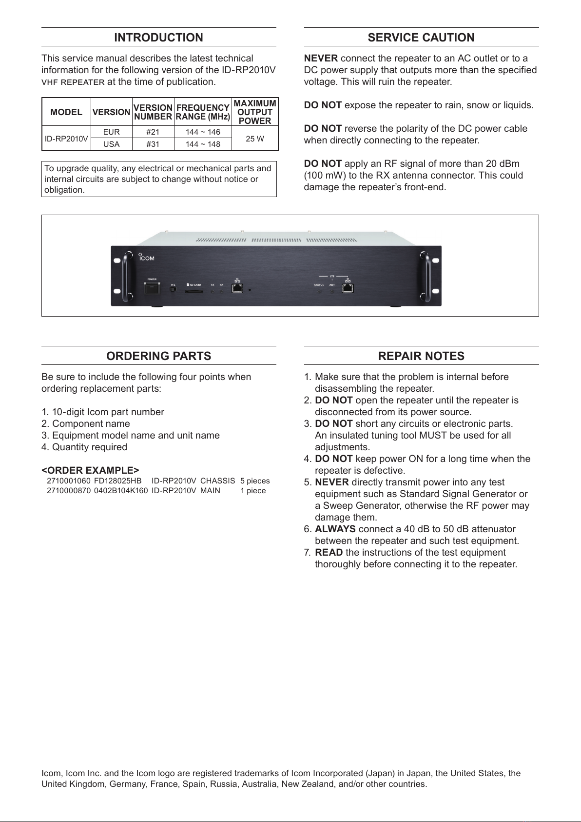
This service manual describes the latest technical
information for the following version of the ID-RP2010V
at the time of publication.
To upgrade quality, any electrical or mechanical parts and
internal circuits are subject to change without notice or
obligation.
ORDERING PARTS
Be sure to include the following four points when
ordering replacement parts:
1. 10-digit Icom part number
2. Component name
3. Equipment model name and unit name
4. Quantity required
<ORDER EXAMPLE>
2710001060 FD128025HB ID-RP2010V CHASSIS 5 pieces
2710000870 0402B104K160 ID-RP2010V MAIN 1 piece
REPAIR NOTES
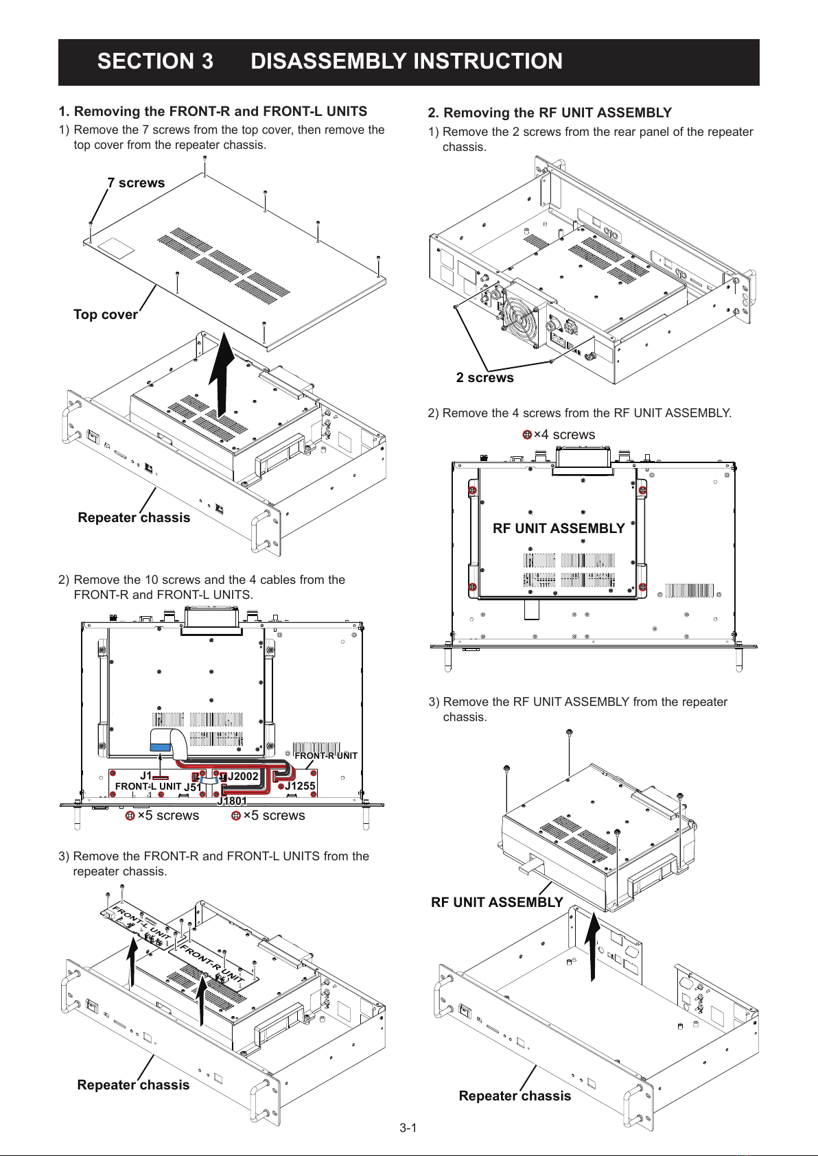
1. Make sure that the problem is internal before
disassembling the repeater.
2. DO NOT open the repeater until the repeater is
disconnected from its power source.
3. DO NOT short any circuits or electronic parts.
An insulated tuning tool MUST be used for all
adjustments.
4. DO NOT keep power ON for a long time when the
repeater is defective.
5. NEVER directly transmit power into any test
equipment such as Standard Signal Generator or
a Sweep Generator, otherwise the RF power may
damage them.
6. ALWAYS connect a 40 dB to 50 dB attenuator
between the repeater and such test equipment.
7. READ the instructions of the test equipment
thoroughly before connecting it to the repeater.
Icom, Icom Inc. and the Icom logo are registered trademarks of Icom Incorporated (Japan) in Japan, the United States, the
United Kingdom, Germany, France, Spain, Russia, Australia, New Zealand, and/or other countries.
MODEL
VERSION
VERSION
NUMBER
FREQUENCY
RANGE (MHz)
MAXIMUM
OUTPUT
POWER
ID-RP2010V EUR #21 144 ~ 146 25 W
USA #31 144 ~ 148
SERVICE CAUTION
NEVER connect the repeater to an AC outlet or to a
DC power supply that outputs more than the specified
voltage. This will ruin the repeater.
DO NOT expose the repeater to rain, snow or liquids.
DO NOT reverse the polarity of the DC power cable
when directly connecting to the repeater.
DO NOT apply an RF signal of more than 20 dBm
(100 mW) to the RX antenna connector. This could
damage the repeater’s front-end.

TABLE OF CONTENTS
SECTION 1 SPECIFICATIONS
SECTION 2 INSIDE VIEWS
SECTION 3 DISASSEMBLY INSTRUCTION
SECTION 4 OPTIONAL PRODUCT INSTALLATION
4-1 INSTALLING THE LTE MODULE (UX-262)……………………………………………………………………… 4-1
4-2 CONNECTING A GATEWAY SERVER ………………………………………………………………………… 4-7
4-3 REPEATER SETTINGS …………………………………………………………………………………………… 4-8
SECTION 5 INTERFACE INFORMATION
SECTION 6 ADJUSTMENT PROCEDURE
6-1 PREPARATION …………………………………………………………………………………………………… 6-1
6-2 TRANSMIT ADJUSTMENTS AND VERIFICATIONS ………………………………………………………… 6-6
6-3 FREQUENCY VERIFICATION …………………………………………………………………………………… 6-7
6-4 RECEIVE VERIFICATIONS ……………………………………………………………………………………… 6-7
6-5 RESTARTING THE REPEATER ………………………………………………………………………………… 6-7
SECTION 7 PARTS LIST
SECTION 8 MECHANICAL PARTS
SECTION 9 BOARD LAYOUTS
SECTION 10 WIRING DIAGRAM
SECTION 11 BLOCK DIAGRAM
SECTION 12 VOLTAGE DIAGRAM

1-1
SECTION 1 SPECIFICATIONS
GENERAL
• Operating frequency range: USA
EUR
144 ~ 148 MHz
144 ~ 146 MHz
• Type of emission: ID
FM
DV
F2A
F3E
F7W
• Antenna impedance:
• Antenna connector type: N-Type
• Operating temperature range:
• Frequency stability: ±0.5 ppm
• Frequency resolution: 1 Hz
• Transfer rate: 4.8 kbps (DV mode)
• TX High
TX Low
Maximum AF output
9.0 A or less
4.0 A or less
1.8 A or less
• Power supply voltage:
• Dimensions:
(Projections not included)
19 (W) × 3.5 (H) × 10.8 (D) inches
• Weight (Approximate):
TRANSMITTER
• Output power:
• Modulation system: FM
DV
Digital reactance modulation
Digital GMSK modulation
• Maximum frequency deviation: FM narrow
FM wide
± 2.5 kHz
± 5.0 kHz
• Occupied bandwidth: 6 kHz or less (DV)
• Spurious emissions: Harmonics –63 dB or less
Out-of-band emission
–60 dB or less
RECEIVER
• Receive system: RF direct sampling
• Sensitivity: FM
DV
• Selectivity: FM (BW: 15 kHz)
DV
• Intermodulation: –60 dB or less
• Receive spurious: 2 nW (–57 dBm) or less
• Spurious & image rejection: More than 55 dB
• Audio output power:
• AF output impedance:
LMeasurements made without an antenna.
L

2-1
SECTION 2 INSIDE VIEWS
• FRONT-L UNIT
J2
J21 ([SD CARD])
ETHERNET ISOLATION
TRANSFORMER
(T10)
J31
J51
J1
• FRONT-R UNIT
J2002
J1801
J1951
J1255

2-2
• MAIN UNIT
TRIPLE INVERTER
(IC5108)
+5 V REGULATOR
(IC1221)
J9001
J3121
ADC SAMPLING CLOCK
OSCILLATING CIRCUIT
DV DSP CORE CLOCK
GENERATOR CIRCUIT
J7931
J8801
J5101 ([CONT I/O])
FPGA*
(IC7601)
ALC AMPLIFIER
(IC2601)
LAN DRIVER
(IC1901)
USB BRIDGE
(IC1551)
SUB CPU
(IC311)
MAIN CPU*
(IC101)
D/A CONVERTER
(IC2001)
A/D CONVERTER
(IC2101)
DC AMPLIFER
(IC2081)
OCTAL BUS BUFFER
(IC5101)
3.3 V REGULATOR
(IC1011)
DC–DC CONVERTER CIRCUIT
DV DSP
(IC502)
FLASH ROM*
(IC331)
J881
CPLD*
(IC8813)
ALC AMPLIFIER
(IC2541)
METER AMPLIFIER
(IC2621)
EXPANDER
(IC2801)
EXPANDER
(IC2821)
D/A CONVERTER
(IC2851)
EXPANDER
(IC2811)
BUFFER
(IC2861)
J3111
J3081
J8661
J3101
J302
J9501
AF AMPLIFER
CIRCUIT
J311
J101
J6451
J5201 ([RPT1/RPT2])
J1621
J301
J7402 ([SP])
J9151
J9401
J9101
LIMITTER AND
FILTER CIRCUIT
RF AMPLIFIER
CIRCUIT
*Mounted under the sheild cover

2-3
• RF-TX UNIT
FORWARD/REFLECTED WAVE
DETECTED VOLTAGE BUFFER
(IC691)
J1
DRIVE AMPLIFIER
(Q201)
PRE-DRIVE AMPLIFIER
(IC101)
POWER AMPLIFIER BIAS VOLTAGE
BUFFER
(IC211)
POWER AMPLIFIER
(Q301)
J101

2-4
• RF-RX UNIT
+5 V REGULATOR
(IC1162)
RF AMPLIFIER
(IC1161)
SCHOTTKY DIODE
(D22)
J1201
CURRENT DETECTOR
(IC51)
PRE AMPLIFIER SWITCH
(Q701)
POWER MOSFET
(Q31)
ZENER DIODE
(D23)
5 A FUSE
(F21)
J1 J41

3-1
SECTION 3 DISASSEMBLY INSTRUCTION
1. Removing the FRONT-R and FRONT-L UNITS
1)
Remove the 7 screws from the top cover, then remove the
top cover from the repeater chassis.
2) Remove the 10 screws and the 4 cables from the
FRONT-R and FRONT-L UNITS.
3) Remove the FRONT-R and FRONT-L UNITS from the
repeater chassis.
2. Removing the RF UNIT ASSEMBLY
1)
Remove the 2 screws from the rear panel of the repeater
chassis.
FRONT-L UNITFRONT-L UNIT
FRONT-R UNITFRONT-R UNIT
×5 screws ×5 screws
J1
J51
J1801
J1801
J1255
J2002
7 screws
Top cover
Repeater chassis
FRONT-L UNITFRONT-L UNIT
FRONT-R UNITFRONT-R UNIT
Repeater chassis
×4 screws
RF UNIT ASSEMBLY
2 screws
RF UNIT ASSEMBLY
Repeater chassis
2) Remove the 4 screws from the RF UNIT ASSEMBLY.
3) Remove the RF UNIT ASSEMBLY from the repeater
chassis.

3-2
(Continued on the right above)
3) Remove the 21 screws and disconnect the cables from
the RF-RX and RF-TX UNITS.
4) Remove the RF-RX and RF-TX UNITS from the chassis.
3.
Removing the RF-RX and RF-TX UNITS
1)
Remove the 15 screws from the top cover, then remove it.
2) Remove the DC cables from the RF-RX and RF-TX
UNITS, and unsolder the antenna connectors (ground).
15 screws
Top cover
Chassis
(RF UNIT ASSEMBLY)
9 screws
12 screws
RF-TX UNIT
RF-RX UNIT
Chassis
(RF UNIT ASSEMBLY)
RF-RX UNIT
RF-TX UNIT
EP22
EP62
EP63
EP301
EP302
EP21
Unsolder
×12 screws
×9 screws
from RF-RX UNIT from RF-TX UNIT
RF-RX UNIT RF-TX UNIT
J1
J41
J1201
J1
J101

3-3
MAIN UNIT
×15 screws
J2881
J8801
J9151
J9001 J9101
J3081
J3101
J9541
MAIN UNIT
4. Removing the MAIN UNIT
1) Turn the RF UNIT ASSEMBLY upside down.
Chassis
(RF UNIT ASSEMBLY)
2) Remove the 15 screws, and disconnect the 8 cables from the
MAIN UNIT.
3) Remove the MAIN UNIT from the chassis i
n the direc-
tion of the arrow
.

4-1
SECTION 4 OPTIONAL PRODUCT INSTALLATION
■SUPPLIED ACCESSORIES
4-1 INSTALLING THE LTE MODULE (UX-262)
LTE antennas*
(Cable length: 3 m, 9.8 ft)
*Includes a cleaning cloth
(7.5 × 80 mm, 0.3 × 3.1 in)
Coaxial cables
(Cable length: 30 cm, 11.8 in)
(For only the USA version)
DPreparation
The system with a single repeater:
Confirm the repeater is connected to a Gateway Server.
The system with multiple repeaters:
Install the unit to a repeater that is connected to a Gateway Server.
connected to other repeaters.
About the certication sticker:
CAUTION: DO NOT
NOTE: Place the repeater within reach of the antenna cables to paste the LTE antennas on a window glass.
NOTE: For the latest information, refer to the UX-262 SETTING GUIDE that is available from the Extranet.

4-2
■INSTALLING THE UNIT
1) Remove the screws, and then remove the top cover.
2)
Carefully remove three cables (123), as shown below.
1233) Remove the five screws.
Screws
4) Remove the PCB (FRONT-R UNIT: 1), and then attach
the unit (2).
125)
Secure the unit using the screws removed in step 3.
LFirmly tighten the screws in the order shown below.
235146) Reattach the cables removed in step 2.
Cables
7) Remove the two caps on the rear panel, as shown
below.
Cap
(Continued on the next page)

4-3
8) Remove the nuts and washers from the straight
connectors on the supplied coaxial cables.
Coaxial cable
Nut
Washer
9) Attach one end of the cables to the connectors on
the unit (1), and then attach the other ends through
2)where the
caps were located.
21Connectors
10) Secure the coaxial cables to the rear panel using the
nuts and washers removed in step 8.
LTorque the nuts to approximately 1.5 N•m.
Nut
Washer
1.5 N•m
(Approximate)
■INSTALLING THE UNIT (CONTINUED)

4-4
■INSTALLING THE SIM CARD
Install valid SIM cards, as shown below.
Caution for handling the nanoSIM cards:
•
or a metal window sash to remove any static electricity that may be accumulated
in your body before handling the nanoSIM cards.
• Never directly touch the IC part (metal sections) of the nanoSIM, or the unit's
• Observe the proper direction when installing the card.
• Always carefully install and remove the card.
• Do not apply too much force to the slot cover when removing or replacing a
nanoSIM card. If it is bent or damaged, it will not be usable.
LInstall the nanoSIM card to the SIM1 slot when using the unit with a single nanoSIM card.
IC (Metal sections)
1) Carefully slide the slot cover in the direction of the arrow
(1), and then open it (2).
LDo not apply too much force to the slot cover.
LDo not touch the metal contacts of the slot with your
1●2Slot cover
SIM2
SIM1 Metal contacts
2) Observe the angled corner of the nanoSIM card and
install the card as shown below.
Angle
3) Close the slot cover (1), and then slide it in the
2).
4) Do not apply too much force to the slot cover.
1●25) If you install a second nanoSIM card, repeat steps
1 ~ 3.
6) Reattach the top cover that you removed on page 2.

4-5
■VERIFICATION
Use the Utility for ID-RP3 to verify that the repeater recognizes the installed unit.
1) Connect the PC to the repeater with a unit
LSee the instruction manual included with the repeater
for details of USB driver settings, utility installation,
and connection instructions.
2) Turn ON the repeater.
3) Open the Utility.
4) Select the COM port that the USB cable is connected
to.
5)
menu to display the repeater information.
6)
L
you complete the LTE settings.
DTroubleshooting
The repeater does not turn ON:
Confirm the cable shown below is properly attached.
Cable
“None” is displayed in “Unit”:
Confirm the flat cable shown below is properly attached.
Flat cable
“Connection Error” is displayed in “Line Status”:
section 3.
If the problem is not solved, confirm the cable shown below
is properly attached.
L
L
panel. See the instruction manual included with the
repeater for details.
Cable

4-6
■PLACING ANTENNAS
DAttaching antennas
Attach the supplied antennas as shown below.
DSecuring antennas
Remove the protection sheet on the antenna surface, and
then paste antennas on the window glass.
LClean the window glass using the supplied cleaning cloth
before pasting.
LPlace the two antennas at a distance of at least 20 cm,
7.9 in apart.
LRelocate the antennas if the repeater has a poor
connection.
CAUTION:
• DO NOT use other than the supplied antennas.
• DO NOT forcibly bend or pull the coaxial cables. This may damage the cables.
• DO NOT step on the coaxial cables, place heavy objects on them, or pinch them. This may damage the cables.
• DO NOT touch the coaxial cables with wet hands. This may damage the cables.
• DO NOT apply too much force to the coaxial cable when removing it. This may damage the cables.
Protection sheet
(Red)
At least 20 cm,
7.9 in
Firmly secure by turning the nut in
the direction of the arrow.

4-7
4-2 CONNECTING A GATEWAY SERVER
■USING A GATEWAY SERVER
Trust
server
Internet
eth0
(To the LTE)
eth1 (To the repeater)
Gateway server
(Linux PC)

4-8
4-3 REPEATER SETTINGS
This section describes about the required IP address and LTE settings in the Utility for ID-RP3.
L
■USING A GATEWAY SERVER
Trust
server
Internet
Gateway server
(Linux PC)
eth0 (To the LTE)
10.0.0.200/8
GW: 10.0.0.201
eth1 (To the repeater)
172.16.0.20/24
[LAN 2]
10.0.0.201/8
[LAN 1]
172.16.0.1/24
Digital Network

4-9
■UTILITY FOR ID-RP3 SETTINGS (COMMON)
The settings shown below are the minimum required to use
the Digital Repeater function. See the Utility for ID-RP3
HELP for more details for other setting items.
DRX Frequency/TX Frequency
L×” is displayed when frequencies are set to default.
L
repeater.
DMode
L
ID-RP1200VD.
DCall Sign
Enter the repeater call sign assigned to it.
LAn Emergency Stop command provided through the LAN
is usable by setting the call sign.
DSquelch Level
Enter the squelch level at which the squelch just opens, and
the repeater starts operating.
DSelecting the output power
Select the output power using the [H/L] switch on the
L
Other manuals for ID-RP2010V
1
Table of contents
Other Icom Repeater manuals

Icom
Icom IC-RP1520 User manual

Icom
Icom IC-FR3000 Series User manual

Icom
Icom UHF IC-FR6000 Installation and operating instructions

Icom
Icom id- rp2 User manual

Icom
Icom IC-RP2210 Service manual

Icom
Icom X BAND 50 User manual

Icom
Icom IC-RP4520 User manual

Icom
Icom IC-FR5100 User manual

Icom
Icom IC-FR5100 Series User manual

Icom
Icom FR3000 User manual

Icom
Icom id- rp2000v User manual

Icom
Icom FR3000 02 User manual

Icom
Icom IC-RP4020 User manual

Icom
Icom ID-RP4000V User manual

Icom
Icom IC-UR8050 User manual

Icom
Icom IC-FR6000-L User manual

Icom
Icom IC-FR3000 Series User manual

Icom
Icom C RP1520 User manual

Icom
Icom IC-FR9020 User manual

Icom
Icom IC-FR6100 User manual