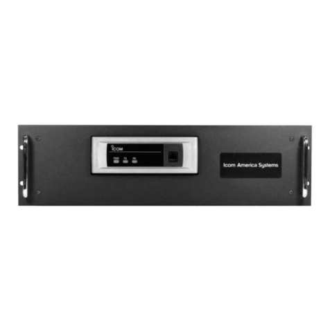
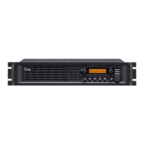
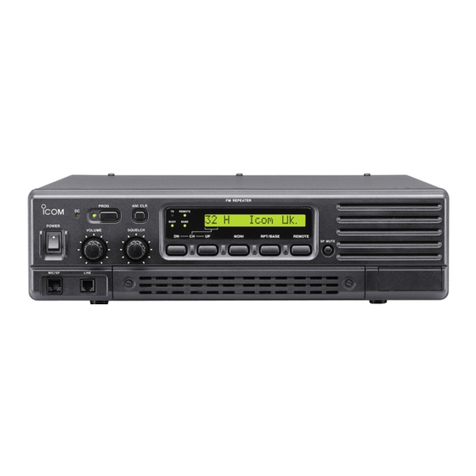
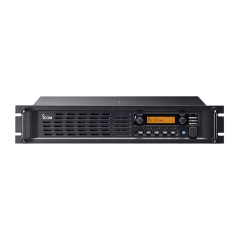
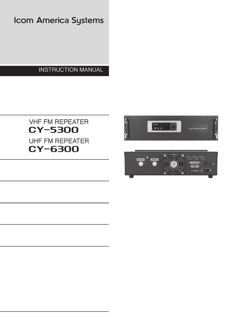
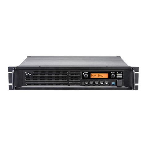
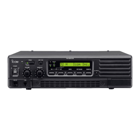
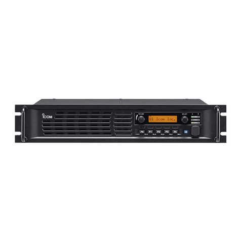
Icom CY-F121S User manual

INSTRUCTION MANUAL
VHF FM REPEATER
UHF FM REPEATER

IMPORTANT
READ THIS INSTRUCTION MANUAL
CAREFULLY
before attempting to operate the
repeater.
SAVE THIS INSTRUCTION MANUAL–
This
manual contains important safety and operating
instructions for the CY-F121S/F221S series.
EXPLICIT DEFINITIONS
WORD
DEFINITION
WARNING
Personal injury, re hazard or electric
shock may occur.
CAUTION
Equipment damage may occur.
NOTE
If disregarded, inconvenience only.
No risk of personal injury, re or
electric shock.
PRECAUTION
WARNING HIGH VOLTAGE! NEVER
attach an antenna or internal antenna connector
during transmission. This may result in an
electrical shock or burn.
WARNING HIGH VOLTAGE! NEVER
install the antenna at any place that person can
touch the antenna easily during transmission.
This may result in an electrical shock or burn.
NEVER
apply AC to the [BATTERY] terminals
on the repeater rear panel. This could cause a
re or damage the repeater.
NEVER
apply more than 16 V DC, such as a
24 V battery, to the [BATTERY] terminals on the
repeater rear panel. This could cause a re or
damage the repeater.
NEVER
let metal, wire or other objects touch
any internal part or connectors on the rear panel
of the repeater. This may result in an electric
shock.
NEVER
expose the repeater to rain, snow or
any liquids.
AVOID
using or placing the repeater in areas
with temperatures below –30°C (–22°F) or above
+60°C (+140°F). Be aware that temperatures
on a vehicleʼs dashboard can exceed 80°C
(+176°F), resulting in permanent damage to the
repeater if left there for extended periods.
AVOID
placing the repeater in excessively dusty
environments or in direct sunlight.
AVOID
putting anything on top of the repeater.
This will obstruct heat dissipation.
Place the repeater in a secure place to avoid
inadvertent use by children.
BE CAREFUL!
The heatsink will become hot
when operating the repeater continuously for long
periods.
BE CAREFUL!
If a linear ampli er is
connected, rst set the repeaterʼs RF output
power to less than the linear ampli erʼs maximum
input level, otherwise, the linear ampli er will be
damaged.
Use Icom microphones only (optional). Other
manufacturerʼs microphones have different pin
assignments, and connection to the C
Y-F121S/
CY-F221S
series may damage the repeater.
For U.S.A. only
CAUTION:
This repeater is intended for use
as a xed base station with the antenna located
outdoors on the rooftop or on antenna tower,
or indoors with the antenna located near the
repeater.
The Icom America Systems logo is a trademark
of Icom, Inc.
The Icom America Systems logo is a trademark
of Icom, Inc.
i

FORWARD
Thank you for purchasing this Icom America
Systems
CY-F121S/221S
VHF/UHF FM REPEATER.
With proper care, this product should provide
you years of trouble-free operation.
FEATURES
❍
20 W continuous full duty cycle operation
This repeater looks as good as it performs.
❍
Automatic battery backup system
A built-in backup system supports automatic
switching to an external power supply (13.6
V DC) if the AC power supply fails.
❍
Multiple CTCSS & DTCS tone memories
One CTCSS/DTCS tone (TX/RX tones
respectively) can be programmed in a
channel. Ideal for many different applications.
❍
Other features
- PC programmable
- 19 inch rack mount or desktop.
SUPPLIED ACCESSORIES
The following accessories are supplied with
CY-F121S/221S series
[AC120V version]
➀
AC power cable (OPC-510) ….............……… 1
Spare fuses (FGB 20A) ………..……….…… 1
➂
DC Power Cord ……..................……….…… 1
ii

➊
MICROPHONE/SPEAKER CONNECTOR
[MIC/SP]
This 8-pin modular jack accepts the optional
microphone.
➀
+8 V DC output (Max. 10 mA)
➁
CLO (output port for PC
programming)
➂
AFO
➃
M PTT (Input port for TX control)
➄
Microphone ground
➅
Microphone input
➆
Ground
➇
CLI (Input port for PC program-
ming and
monitor control)
➋
VOLUME CONTROL [VOLUME]
Adjusts the audio output level.
➌
DEALER PROGRAMMABLE KEYS
P0, P1, P2, P3
➍
POWER SWITCH [POWER]
Push to turn the power ON and OFF.
➎
INTERNAL SPEAKER
Monitors received signals.
➏
TRANSMITTER UNIT
➐
RECEIVER UNIT
➀➇
1
PANEL DESCRIPTION
■
Front Panel
➊
➋
➌
➍
➎
➎
1
➏
➏
➐

■
Front Panel
PANEL DESCRIPTION 1
➊
AF VOLUME CONTROL KNOB
Rotate the knob to adjust the audio output
level.
• Minimum audio level is pre-programmed.
➋
FUNCTION DISPLAY
Displays a variety of information, such as an
operating channel number/name.
NOTE:
The above functions depend on
pre-programming.
➌
POWER SWITCH [POWER]
Push to turn the power ON and OFF.
• The following functions are available at
power ON as options:
- Automatic scan start
-Password prompt
-Set mode
➍
DEALER-PROGRAMMABLE KEYS
[P0] to [P3]
Desired functions can be programmed
independently by your dealer.
➎
MICROPHONE CONNECTOR
Connect the supplied microphone or optional
DTMF microphone for SmarTrunk II™
operation here.
NEVER
connect non-speci ed microphones.
The pin assignments may be different and
the transceiver may be damaged.
➋
➋
➌
➌
➊
➊
➎
➎
➍
➍
■
Function LED
➋
TX/RX INDICATOR
➥
Lights red: while transmitting
➥
Lights green: while the channel is busy
➥
Blinks orange (green and red blink simultaneous-
ly): when the speci ed 2-tone, 5-tone call is received.
➥
Green and red blink alternately: cloning error
➌
ACTIVATED KEY INDICATOR (LP 0/1/2)
Indicates relative receive signal strength level.
NOTE
: When all function LEDs blink, check the DC
battery voltage is not too high.
➊
CHANNEL INDICATORS
➥
Indicates the operating channel.
➥
Blinks when receiving a signal during
scanning operation.
➥
All LEDs blink while entering the power
ON password.
2

➊
POWER SWITCH [POWER]
Toggles to turn the repeater power ON or
OFF. Located on the back panel of the
repeater.
➋
TRANSMIT ANTENNA CONNECTOR [TX/
TRANSMIT ANTENNA CONNECTOR [TX/ TRANSMIT ANTENNA CONNECTOR [TX/
TX•RX]
➥
Connects a transmit antenna (impedance:
50 Ω) and outputs transmit signals.
➥
When installing an optional internal
duplexer (supplied by third party), this
connects the transmit and receive to an antenna.
➌
ACCESSORY CONNECTOR [ACC]
Connects to a remote controller.
• See pgs. 3, 4 for accessory connector
information.
➍
RECEIVE ANTENNA CONNECTOR [RX]
➥
Connects a receive antenna (impedance: 50
Ω) and inputs receiving signals.
➥
When installing an internal duplexer
(supplied by third party), do not use this
connector.
➎
AC POWER SOCKET [AC]
Connects the supplied AC power cable to a
domestic AC outlet.
➏
GROUND TERMINAL [GND]
Ground the repeater through this terminal
to prevent electric shocks, TVI, BCI and other
problems.
➐
DC POWER INPUT TERMINALS [BATTERY
]
Connects a 12 V storage battery for
repeater backup when AC power is
interrupted. These terminals are also used
for DC power operation.
CAUTION: NEVER
short the (+) line of the
DC power cable to repeaterʼs chassis. There
is danger of electric shock and/or equipment
damage.
■
Rear Panel
PANEL DESCRIPTION 1
3
➊
➋
➌
➍
➎
➏
➐

■
Repeater Controller
Programming Mobile Radios
➀
Transmitter:
• Go to LMR>Memory CH>Free, Program the
TX and RX to the transmit frequency
•
Set the CTCSS/CDCSS Tone
•
Set RF Power to High
• Go to LMR>Common>Expert, Set EPTT/
• Go to LMR>Common>Expert, Set EPTT/ • Go to LMR>Common>Expert, Set EPTT/
FTSW to EPTT (to allow ExtPTT)
* Inside the TX radio, Short jumper D and solder
TXData to F
➁
Receiver:
•
Go to LMR>Memory CH>Free, Program the RX
frequency
•
Set the CTCSS/CDCSS Tone
•
Enable TX inhibit
•
Set RF Power to LOW2
•
Go to LMR>Common>Expert, set RX EXO to ON
(to enable Signal HORN, CSQ, and PL/DPL)
CABLE CONNECTORS
X1
Accessory Connector TX
X2
Accessory Connector RX
X3
FAN
X4
J6 Optional Connector RX
X5
J6 Optional Connector TX
JP2
Repeater Disable
JP3
Transmit On
JP4
Hang On Time
JP5
Hang On Time
JP6
Hang On Time
JP7
Hang On Time
JP8
Audio On
JUMPER SETTINGS
JP7
JP6
JP5
JP4
T sec.
1
1
1
1
0
0
1
1
1
0.5
1
0
1
1
1
1
0
1
1
1.5
1
1
0
1
2
0
1
0
1
2.5
1
0
0
1
3
0
0
0
1
3.5
1
1
1
0
4
0
1
1
0
4.5
1
0
1
0
5
0
0
1
0
5.5
1
1
0
0
6
0
1
0
0
6.5
1
0
0
0
7
0
0
0
0
7.5
HANG ON TIME CONFIGURATION
** 1 = ON; 0 = OFF
PANEL DESCRIPTION 1
4

5

6

Pin
No.
Pin Name
Description
Speci cation
6
Vcc TX
+15V DC Supply for External Controller, TX
Unit
Maximum 1 A
7
GND TX
DC Ground, TX Unit
8
Busy TX
Output Terminal for Busy Signal, TX Unit
Open
Open
Collector+OFF, 0V=ON
9
AFO TX
Audio Output, TX Unit
10
DISC TX
Discriminator Output, TX Unit
11
TXA TX
Transmit Audio, TX Unit
12
PTT TX
External PTT, TX Unit
13
TXD TX
Transmit Data Input, TX Unit
18
Vcc RX
+15V DC Supply for External Controller, RX
Unit
19
GND RX
DC Ground, RX Unit
20
Busy RX
Output Terminal for Busy Signal, RX Unit
21
AFO RX
Audio Output, RX Unit
22
DISC RX
Discriminator Output, RX Unit
23
TXA RX
Transmit Audio, RX Unit
24
PTT RX
External PTT, RX Unit
25
TXD RX
Transmit Data Input, RX Unit
■
Accessory connector
PANEL DESCRIPTION 1
DB25 Pin Outs Con guration
7

2
INSTALLATION AND CONNECTIONS
■
Unpacking
After unpacking, immediately report any damage
to the delivering carrier or dealer. Keep the
shipping cartons.
For a description and a diagram of accessory
equipment included with the CY-F121S/221S
series, see ʻSupplied accessoriesʼ of this
manual.
■
Selecting a location
Select a location for the repeater that allows
adequate air circulation, free from extreme
heat, cold, or vibrations, and away from TV
sets, TV antenna elements, radios and other
electromagnetic sources.
■
Antenna connection
For radio communications, the antenna is of
critical importance, along with output power and
sensitivity. Select antenna(s), such as a well-
matched 50 Ω antenna, and feedline. 1.5:1 or
better of Voltage Standing Wave Ratio (VSWR)
is recommended for desired band. Of course, the
transmission line should be a coaxial cable.
CAUTION: Protect repeater from lightning
by using a lightning arrestor.
NOTE: There are many publications
covering proper antennas and their
installation. Check with your local dealer for
more information and recommendations.
■
Duplexer
A duplexer is separately required when only
one antenna is used for both transmitting and
receiving. Select a duplexer according to the
transmitting and receiving frequencies. Ask your
Dealer for details.
■
Grounding
To prevent electrical shock, television interference
(TVI), broadcast interference (BCI) and other
problems, ground the transceiver through the
[GND] terminal on the rear panel.
For best results, connect a heavy gauge wire or
strap to a long earth-sunk copper rod. Make the
distance between the [GND] terminal and ground
as short as possible.
WARNING:
NEVER
connect the
[GND] terminal to a gas or electric pipe,
since the connection could cause an
explosion or electric shock.
TYPE-N CONNECTOR INSTALLATION EXAMPLE
Slide the nut, at washer, rubber gasket and clamp over the coaxial
cable, then cut the end of the cable evenly.
Strip the cable and fold the braid back over the clamp.
Soft solder the center conductor. Install the center conductor pin and
solder it.
solder it.
Carefully slide the plug body into place aligning the center conductor
pin on the cable. Tighten the nut onto the plug body.
30 mm ≈ 9⁄8 in 10 mm ≈ 3⁄8 in 1–2 mm ≈ 1⁄16 in
➀
➀
➁
➁
➂
➂
➃
➃
8

■
Required Connections
INSTALLATION AND CONNECTIONS 2
[DC POWER INPUT TERMINAL]
Make sure the back up battery is correctly
connected. Use a cable with following
current capacity. Solder or clamp the cable
plug when connecting the power cable to the
backup battery to prevent voltage drops.
Power cable current capacity: 25 A or more
[TX(TX•RX) ANT]
[TX(TX•RX) ANT]
[RX ANT] GROUND
[RX ANT] GROUND
[RX ANT] GROUND
[RX ANT] GROUND
TX•RX antenna required
for installing an internal
duplexer.
9

Make sure the [POWER] switch is turned OFF
when connecting an AC power cable or a backup
battery (emergency power supply).
The CY-F121S/221S series can operate with an
AC or DC power supply. If AC power is interrupted
when operating the repeater with an AC power
supply, power is automatically provided to the
[BATTERY] terminals.
NOTE:
If turning the repeater OFF using the
rear panel switch, wait a few seconds before
turning it back ON. Otherwise, Logic circuits
may not sense the transition and operate
correctly.
In AC operation
• Use the supplied AC power cable for
connection to a domestic AC outlet.
• Extension cords should not be used unless
absolutely necessary. Using improper
extension cords could result in re risk.
In DC operation
CAUTION:
Voltages greater than 16 V DC
will damage the repeater. Check the source
voltage before connecting the power cable.
•
DO NOT place the backup battery on or near
the repeater. Lead-acid batteries should be
placed at least 5 m (16.4 ft.) away from the
repeater. Use a heavy duty cable to make
the connection and be sure both the positive
(red) and negative (black) terminals are
correctly connected.
•
When connecting to the battery, connect the
DC power cable to the repeater rst, then
the positive (red) terminal and negative
(black) terminal to the battery. This is to
prevent electric shock or circuit damage.
■
Power
INSTALLATION AND CONNECTIONS 2
10

3
O
PTIONAL UNIT INSTALLATION
■
Opening the repeaterʼs case
Follow the case and cover opening procedures
shown here when an optional unit is installed or
adjust the internal units, etc.
CAUTION: Disconnect
the AC power cable
and/or DC power cable from the repeater.
Otherwise, there is danger of electric shock
and/or equipment damage.
➀
Remove 7 screws from the top of the repeater
and 4 screws from the sides, then lift up the
top cover.
➁
Turn the repeater upside down.
11

4
OPERATION
■
Turning power ON
➀
On rear panel, push [POWER] to turn power
ON.
■
Receiving and transmitting
Receiving
➀
Push [POWER] to turn power ON.
➁
Rotate [VOLUME] to adjust the audio
output level.
➂
Push [1; 2; 3; 4] to select the desired
channel.
•When receiving a signal, BUSY indicator turns ON
and audio is emitted from the speaker.
•Further adjustment of [VOLUME] to a comfortable
listening level may be necessary at this point.
Transmitting
➀
Take the microphone off hook.
➁
Wait for the channel to become clear.
➂
Push and hold [PTT] to transmit, then
speak into the microphone at your normal
voice level.
➃
Release [PTT] to receive.
IMPORTANT:
To maximize the readability of the transmitted
signal:
(1) Pause brie y after pushing [PTT].
(2) Hold the microphone 1 to 2 inch (2.5 to
5 cm) from your mouth, then speak into
the microphone at a normal voice level.
12

5
MAINTENANCE
■
Fuse replacement
If a fuse blows or the repeater stops functioning,
try to nd the source of the problem, and replace
the damaged fuse with a new, rated fuse.
Replace the circuitry fuse as shown below.
WARNING:
DISCONNECT
the AC
power cable and/or DC power cable from
the repeater. Otherwise, there is danger of
electric shock and/or equipment damage.
“There are two fuses:
The left fuse, as pictured, is for repeater TX
The right fuse is for repeater RX”
13

6
SPECIFICATIONS AND OPTIONS
■
Speci cations
◆
CY-F121S
General
•Frequency coverage
: 136.000-174.000 MHz*
•Channel spacing
: 12.5/25 kHz (Narrow/Wide)
•Number of channels
: Max 8 channels
•Antenna connector
: SO-293 (50Ω)
•Power supply voltage
: 13.2 V DC nominal [25W]
(Negative ground)
13.6 V DC nominal [50W]
•Current drain (apporx.)
: TX (25W)
7.0 A
(50W)
13.0 A
Max. Audio
1.2 A
Stand-by
0.3 A
•Operating temp. range
: -30 °C to +60 °C
(-22 °F to +140 °F)
•Dimensions (Projections not included)
[25W]:
480 (W) x 133 (H) x
364 (D) mm; 18.90 (W) x
5.24 (H) x 14.33 (D) inches
[50W]:
480 (W) x 133 (H) x
364 (D) mm; 18.90 (W) x
5.24 (H) x 14.33 (D) inches
•Weight:
8.6 kg; 18 lb
[25W]
8.6 kg; 18 lb
[50W]
•RF output power:
25W/10W/2.5W
[25W]
(High/Low2/Low1)
50W/25W/5W
[50W]
•Modulation system:
Variable reactance freq.
modulation
•Max. frequency deviation:
±2.5 kHz
[Narrow]
±5.0 kHz
[Wide]
•Frequency Error:
±5.0 ppm
•Spurious emission:
70 dB typical
•Adjacent channel power:
60 dB
[Narrow]
70 dB
[Wide]
•Audio frequency response: +2 dB to -8 dB of
6 dB/octave range from:
300 Hz to 2550 Hz [Narrow]
300 Hz to 3000 Hz [Wide]
•Audio harmonic distortion
: 3% typical at 1 kHz , 40%
deviation
•FM Hum and noise:
40 dB
[Narrow]
(typical, with CCIT lter) 46 dB
[Wide]
•Limiting character of:
70-100% of max deviation
modulation
•Microphone connector:
8-pin modular (600Ω)
Receiver
•Receive system:
Double-conversion
superheterodyne system
•Intermediate frequency:
1
st
: 46.35 MHz, 2
nd
: 450 kHz
•Sensitivity:
0.25 µV at 12 dB SINAD
•Squelch sensitivity:
0.25 µV
•Adjacent channel:
65 dB
[Narrow]
Selectivity (typical)
75 dB
[Wide]
•Spurious response:
75 dB
•Intermodulation (typical):
74 dB
•Hum and Noise (typical):
40 dB
[Narrow]
45 dB
[Wide]
•Audio output power:
4W typical at 10% distortion
with a 4Ω load
•External SP connector:
2-conductor 3.5 (d) mm
(
1
/
8
/8
/
”)/4Ω
◆
CY-F221S
General
•Frequency coverage:
400.000-430.000 MHz*
440.000-490.000 MHz*
•Channel spacing:
12.5/25 kHz (Narrow/Wide)
•Number of channels:
Max 8 channels
•Antenna connector:
SO-293 (50Ω)
•Power supply voltage:
13.6 V DC nominal
(negative ground)
•Current drain (apporx.):
TX (25W)
7.0 A
(45W)
13.0 A
Max. Audio
1.2 A
Stand-by
0.3 A
•Operating temp. range:
-30 °C to +60 °C
(-22 °F to +140 °F)
•Dimensions (Projections not included)
[25W]:
480 (W) x 133 (H) x
364 (D) mm; 18.90 (W) x
5.24 (H) x 14.33 (D) inches
[45W]:
480 (W) x 133 (H) x
364 (D) mm; 18.90 (W) x
5.24 (H) x 14.33 (D) inches
•Weight:
8.6 kg; 18 lb
[25W]
8.6 kg; 18 lb
[45W]
Transmitter
•RF output power:
25W/10W/2.5W
[25W]
(High/Low2/Low1)
50W/25W/4.5W
[45W]
14

•Modulation system:
Variable reactance freq.
modulation
•Max. frequency deviation:
±2.5 kHz [Narrow]
±5.0 kHz [Wide]
•Frequency Error:
±2.5 ppm
•Spurious emission:
70 dB typical
•Adjacent channel power:
60 dB
[Narrow]
70 dB
[Wide]
•Audio frequency response:
+2 dB to -8 dB of
6 dB/octave range from:
300 Hz to 2550 Hz [Narrow]
300 Hz to 3000 Hz [Wide]
•Audio harmonic distortion:
3% typical at 1 kHz , 40%
deviation
•FM Hum and noise:
40 dB
[Narrow]
(typical, with CCIT lter)
46 dB
[Wide]
•Limiting character of:
70-100% of max deviation
modulation
•Microphone connector:
8-pin modular (600Ω)
Receiver
•Receive system:
Double-conversion
superheterodyne system
•Intermediate frequency:
1
st
: 46.35 MHz, 2
nd
: 450 kHz
•Sensitivity:
0.25 µV at 12 dB SINAD
•Squelch sensitivity:
0.25 µV
•Adjacent channe: 65 dB
[Narrow]
Selectivity (typical)
75 dB
[Wide]
•Spurious response:
75 dB
•Intermodulation (typical):
74 dB
•Hum and Noise (typical):
40 dB
[Narrow]
45 dB
[Wide]
•Audio output power:
4W typical at 10% distortion
with a 4Ω load
•External SP connector:
2-conductor 3.5 (d) mm
(
1
/
8
/8
/
”)/4Ω
■
Options
•HM-100 HAND MICROPHONE
•HM-100TN DTMF MICROPHONE
Hand microphone with a DTMF keypad
•SM-25 DESKTOP MICROPHONE
•IAS VHF DUP KIT VHF duplexer kit with RF jumpers
•IAS UHF DUP KIT UHF duplexer kit with RF jumpers
15


MEMO
This manual suits for next models
1
Table of contents
Other Icom Repeater manuals

Icom
Icom FR3000 02 User manual

Icom
Icom FR3000 User manual

Icom
Icom IC-FR5100 Series User manual

Icom
Icom CY-5300 User manual

Icom
Icom IC-FR5200H User manual

Icom
Icom IC-RP4020 User manual

Icom
Icom IC-FR9020 User manual

Icom
Icom IC-FR3000 Series Use and maintenance manual

Icom
Icom D-STAR ID-31A; D-STAR ID-31E User manual

Icom
Icom IC-FR5100 User manual

Icom
Icom IC-FR3000 Series User manual

Icom
Icom IC-RP1520 User manual

Icom
Icom FR9020 11 User manual

Icom
Icom ID-RP1 User manual

Icom
Icom IC-RP1520 User manual

Icom
Icom FR5000 Operating instructions

Icom
Icom ID-RP2C User manual

Icom
Icom iFR5000 User manual

Icom
Icom ID-RP2010V User manual

Icom
Icom IC-RP1520 User manual