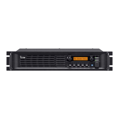
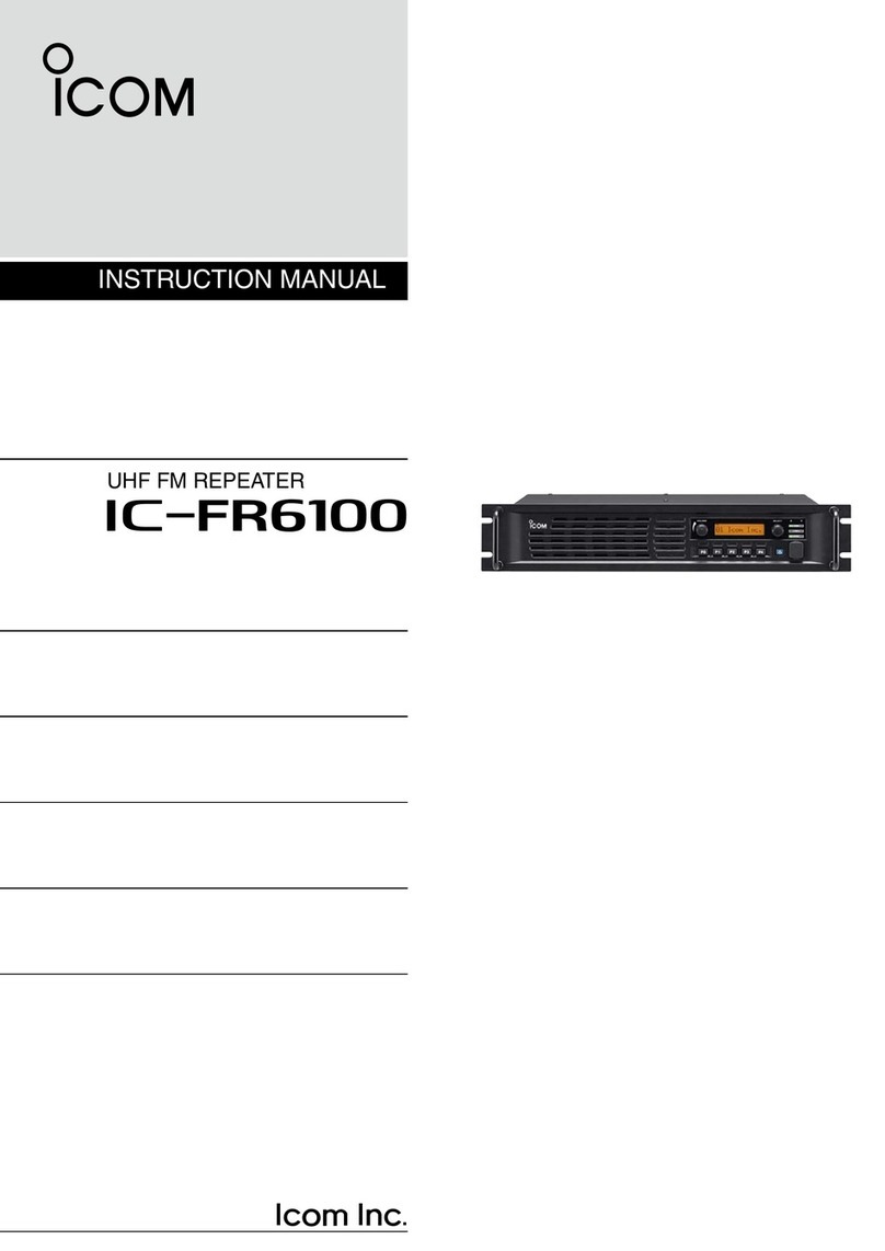
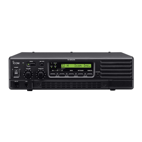
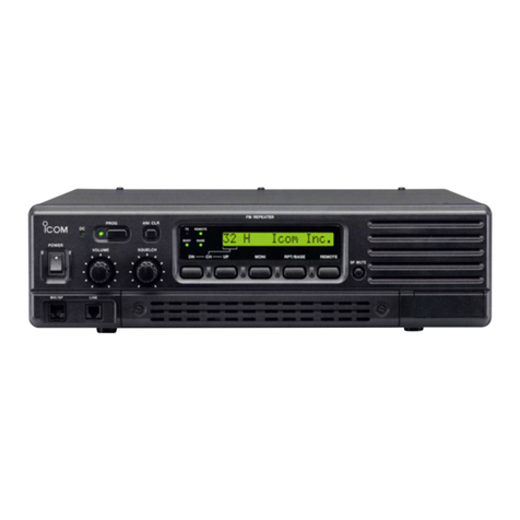
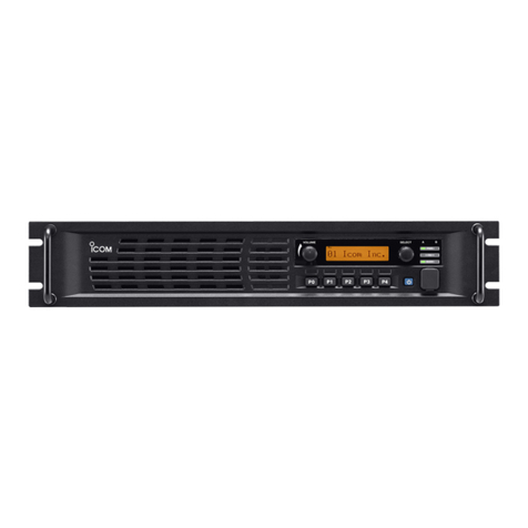
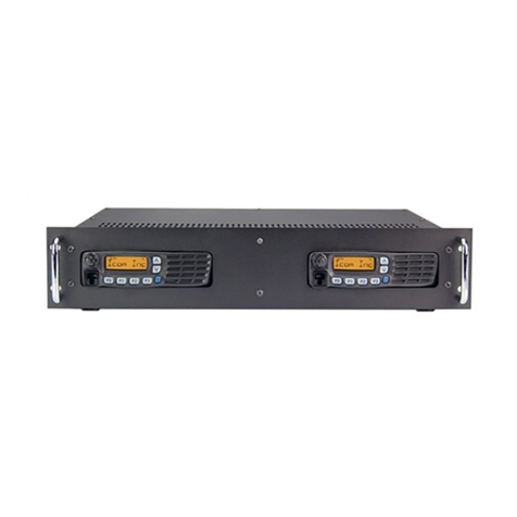
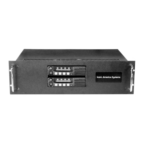
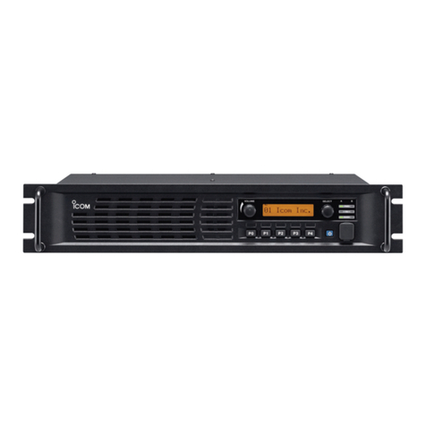
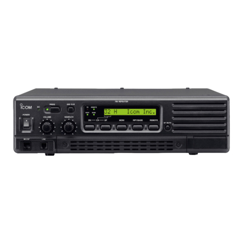
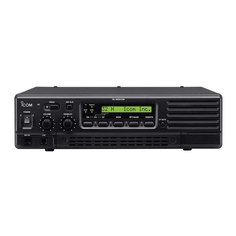
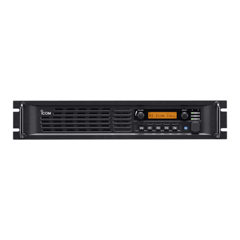
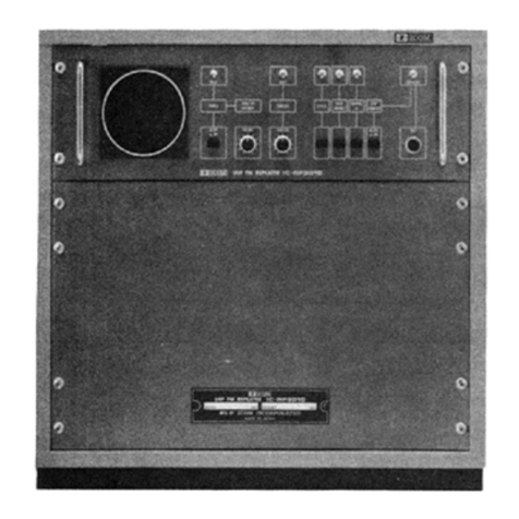
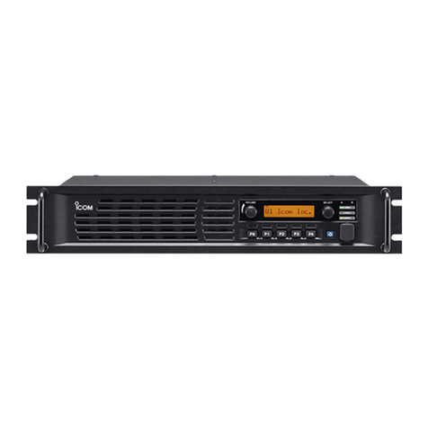
Icom FR5000 Operating instructions

fr5000/fr6000 repeater
idas programming guide
(Includes Trunking)

8/19/2011 i
Table of Contents
What is Covered in this Guide................................................................................................................................1
Before You Start Programming...............................................................................................................................1
Applicable Models...................................................................................................................................................1
Programming Tones in Repeater Mode..................................................................................................................2
Repeater Programming...........................................................................................................................................4
Analog Repeating................................................................................................................................................4
Mixed Analog Repeating .....................................................................................................................................5
Mixed Digital Repeating.......................................................................................................................................6
Digital Repeating.................................................................................................................................................7
Trunking Repeater Programming........................................................................................................................8
Using the External I/O Settings...............................................................................................................................9
Program Settings ..................................................................................................................................................11
Memory CH Window..........................................................................................................................................11
Digital/Option Window.......................................................................................................................................11
Expert Window...................................................................................................................................................11
Appendix A: Temperature/Voltage Output Chart..................................................................................................12
Appendix B: Checking RSSI Levels......................................................................................................................13

8/19/2011 1
What is Covered in this Guide
This guide provides simplified step by step instructions for programming your FR5000/FR6000 repeater. The
programming information covers IDAS 6.25kHz digital programming, including IDAS trunking. It covers repeater
operation only, though the repeater can be used as a base station.
IDAS (Icom Digital Advanced System) is a digital and analog land mobile radio system, using the NXDN™
6.25kHz digital modulation and common air interface protocol.
Before You Start Programming
Check that you have the following:
CS-FR5000 cloning software, latest version
Latest firmware loaded in the Radios, Repeaters, and Trunking Controllers (if applicable)
Repeater power supply
Cloning cable OPC-1122/U
UC-FR5000 Trunking Controller Boards (for trunking applications)
Applicable Models
This Guide applies to the FR5000/FR6000 repeaters only.

2
Programming Tones in Repeater Mode
The FR5000/6000 uses standard analog CTCSS tones and DTCS tones. When in digital mode, the repeater
uses RAN codes. RAN Codes are digital equivalents to CTCSS tones. The codes are decimal, and range from
0 to 63. If you want squelch open to be able to receive all RANs, enter 0. This code allows all RAN codes to be
received and will retransmit using the code that is programmed for transmit in that channel.
When programming tones, the first step is programming tones in the Multiple Table. Here you can enter all
tones/codes: CTCSS, DTCS, and digital RAN codes. This table allows you to assign up to 16 tone sets to a
channel.
1. Navigate to the Multiple Table.
2. Enter the number of the table in the Table No. field that applies to that particular channel
(frequency set).
3. Enter Digital or Analog, then set the desired tones.
4. Navigate to the Memory CH window.
5. Enter the number of the Multiple Table in the Multi Table No. field that you want assigned to your
channel.

8/19/2011 3
Important: If no tones are entered in the Multiple Table field, the radio will respond as described in the
following examples.
Analog Channels
The repeater will receive carrier squelch and will transmit no tones. If there is a tone set in the TX C Tone field
(in the Memory CH), the repeater will transmit this tone.
Digital Channels
The repeater will receive any RAN code and retransmit that RX code.

4
Repeater Programming
Analog Repeating
A repeater set for analog receives and transmits on analog only. Program your radio with the following settings.
All frequencies need to be entered and the squelch level must be set before programming the following
settings.
Common Window
Field
Setting / Description
Others >Digital Function
Set to Enable, for future use of digital channels. Analog
operation is possible with this set to either Enable or Disable.
When enabled, the Digital window appears.
Hold Timer
Set to desired Hang Time of the repeater
Memory CH Window
Multiple Table Window
Field
Setting / Description
Table No.
Set to desired number. Can have as many as 16 tables. If you
have created more than 1 table, entering a number in this field
will bring up the matching table.
Type
Set to Analog.
Decode/Encode
Set to the desired CTCSS tone set. Repeater will operate on all
tone sets entered.
Field
Setting / Description
Operation Mode
Set to Repeat.
Frequency (MHz)
Enter the RX and TX frequencies.
Text
Enter the appropriate text for the channel name.
RF PWR
Set the desired power level. Choices are L1 (5W), L2 (25W),
and High (50W).
CH Type
Set to Analog.
CW ID
>
ON/OFF
Set to ON (the CW window contains the timers and ID).
TX C Tone
Set the CTCSS/DTCS tone here. It is active in repeater mode
only If Multiple Table is not enabled, tones apply to TX only;
RX is open squelch. The front hand mic uses this TX tone.
If RX and TX tones are required, use the Multi Table to set the
tones.
Multi Table No.
Set to the desired table number. It points to the tone settings in
the Multiple Table screen. The repeater will RX and TX for the
assigned channel using all the tone sets referenced in this
window. Note: if there is no value entered, the radio will RX on
any tone and transmit on the tone entered in the TX C. Tone
field.

8/19/2011 5
Mixed Analog Repeating
A repeater set for mixed analog is capable of receiving both digital and analog signals, and will re-transmit in
the format received. The front hand mic will transmit in Analog.
Program your radio with the following settings. All frequencies need to be entered and the squelch level must
be set before programming the following settings.
Common Window
Field
Setting / Description
Others
>
Digital Function
Set to Enable. When enabled, the Digital window appears.
Hold Timer
Set to desired repeater Hang Time.
Memory CH Window
Multiple Table Window
Field
Setting / Description
Table No.
Set to desired number. Can have as many as 16 tables. If you
have created more than 1 table, entering a number in this field
will bring up the matching table.
Type
Set to Analog or Digital.
Decode/Encode
Set to the desired CTCSS tone or RAN code set. Note: RAN
codes are decimal.
Field
Setting / Description
Operation Mode
Set to Repeat.
Frequency (MHz)
Enter RX and TX frequencies
Text
Enter appropriate text for the channel name.
RF PWR Set the desired power level. Choices are L1 (5W), L2 (25W),
and High (50W).
CH Type Set to Mixed-Ana. This allows receiving in analog and digital
and transmitting the same format as was received.
CW ID
>
ON/OFF
Set to ON (the CW window contains the timers and ID).
TX C Tone If the Multiple Table is not enabled, tones apply to TX only; RX
is open squelch. The front hand mic uses this TX tone.
If RX and TX tones are required, use the Multi Table to set the
tones.
Multi Table No.
Set to the desired number. It points to the tone/RAN settings in
the Multiple Table screen. The repeater will RX and TX for the
assigned channel using the tone/RAN sets referenced in this
window. Note: if there is no value entered, the radio will RX on
any tone and transmit on the tone entered in the TX C. Tone
field or, if set to Digital, will have no RAN for RX or TX.
TX RAN
No function in Mixed Analog Mode.
6
Mixed Digital Repeating
A repeater set for mixed digital is capable of receiving both digital and analog signals, and will transmit in the
format received. The front hand mic transmissions will be digital.
Program your radio with the following settings. All frequencies need to be entered and the squelch level must
be set before programming the following settings.
Common Window
Field
Setting / Description
Others
>
Digital Function
Set to Enable. When enabled, the Digital window appears.
Memory CH Window
Multiple Table Window
Field
Setting / Description
Table No.
Set to desired number. Can have as many as 16 tables. If you
have created more than 1 table, entering a number in this field
will bring up the matching table.
Type
Set to Analog or Digital.
Decode/Encode
Set to the desired CTCSS tone or RAN code set. Note: RAN
codes are decimal.
Field
Setting / Description
Operation Mode
Set to Repeat.
Frequency (MHz)
Enter RX and TX frequencies.
Text
Enter appropriate text for the channel name.
RF PWR Set the desired power level. Choices are L1 (5W), L2 (25W),
and High (50W).
CH Type
Set to Mixed-Digi. This allows receiving in analog and digital
and transmitting the same format as was received.
CW ID
>
ON/OFF
Set to ON (the CW window contains the timers and ID).
TX C Tone If the Multiple Table is not enabled, tones apply to TX only; RX
is open squelch. The front hand mic uses this TX tone.
If RX and TX tones are required, use the Multi Table to set the
tones.
Multi Table No.
Set to the desired number. It points to the tone/RAN settings in
the Multiple Table screen. The repeater will RX and TX for the
assigned channel using the tones/RAN’s referenced in this
window. Note: if there is no value entered, the radio will RX on
any tone and transmit on the tone entered in the TX C Tone or,
if set to Digital, will have no RAN for TX and RX.
TX RAN
Front mic functionality only. Repeater will TX this RAN from the
front mic.

8/19/2011 7
Digital Repeating
A repeater set for digital receives and transmits in digital only. Program your radio with the following settings. All
frequencies need to be entered and the squelch level must be set before programming the following settings.
Common Window
Field
Setting / Description
Others
>
Digital Function
Set to Enable. When enabled, the Digital window appears.
Hold Timer
Set to desired Hang Time of the repeater
Memory CH Window
Multiple Table Window
Field
Setting / Description
Table No.
Set to desired number. Can have as many as 16 tables. If you
have created more than 1 table, entering a number in this field
will bring up the matching table.
Type
Set to Analog or Digital.
Decode
/
Encode
Set to the desired RAN code set. Note: RAN codes are
decimal.
Field
Setting / Description
Operation Mode
Set to Repeat.
Frequency (MHz)
Enter RX and TX frequencies
Text
Enter appropriate text for the channel name.
RF PWR
Set the desired power level. Choices are L1 (5W), L2 (25W),
and High (50W).
CH Type
Set to Digital. This allows transmitting in digital and receiving in
digital.
CW ID >ON/OFF
Set to ON (the CW window contains the timers and ID).
Multi Table No.
Set to the desired number. It points to the RAN settings in the
Multiple Table screen. The repeater will RX and TX for the
assigned channel using the RAN codes referenced in this
window. Note: if OFF is selected, the repeater will RX and TX
any matching digital frequency regardless of the RAN codes.
TX RAN
Front hand mic uses this RAN for transmission.

8
Trunking Repeater Programming
The following procedure assumes that the squelch has been set.
1. Go to Memory CH and enter your frequencies if you have not already done so.
2. In the Operation Mode field select Full-Duplex.
3. Go to the Common folder and click Common. Set Digital Function to Enable.
4. Click Clone and write the file into the repeater.

8/19/2011 9
Using the External I/O Settings
The FR5000/6000 cloning software has an interface that allows you to configure ports on the DB-25 connector
for external devices. These settings are in theExternal I/O window. The Port Settings window shows the
ports; each port represents a pin on the connector. The CH Switch Table window allows you to change the pin
assignment.
Ports 15 through 25 can be set as input or output; each has its own set of options. Ports 1 through 14
(excluding port 10) are fixed. You also have the option to set the output to be active low or active high.

10
Port 10 allows you to set power output options for pin 10 of the connector. Power Supply Voltage simply
means that the output pin will reflect the voltage on the power supply. The Temperature setting creates an
output that varies according to the temperature inside the repeater. Appendix A on page 12 lists the range of
temperatures and the corresponding voltages. When using the RSSI setting, the repeater varies the output
based on the RSSI (Receive Signal Strength Indicator) of the radios in the system.
Note: When a port is set to Analog Audible output, be sure to set the AF Min Level (Set Mode window) to 1 or
more. If this is set to 0, there will be no audible output from the assigned pin.

8/19/2011 11
Program Settings
This section defines all of the enhanced feature settings for your radio. In most cases, the default settings will
work best.
Memory CH Window
Field
Description
Suggested Setting
RX RAN
The receive digital code that must match the TX radio RAN
before squelch will open. The range is 0 to 63, with 0
representing open squelch.
User preference
TX RAN
The transmit digital code that must match the RX radio
RAN before squelch will open. The range is 0 to 63, with 0
allowing a match to any RAN code.
User preference
Unit ID
The unique identification for an individual radio.
User preference
Talkgroup ID
The unique identification for a talkgroup.
User preference
Squelch
Type If set to OFF, there is only carrier squelch. If set to RAN,
the digital RAN code must match before a squelch will
open. If set to Sel, the RAN and the Unit ID or Talkgroup ID
must match before squelch will open.
User preference
Digital/Option Window
Field
Description
Suggested Setting
Talkgroup Display
on Mode Change
Enables the Talkgroup ID or Zone to display on the
radio when changing the channel or zone.
User preference
Talkgroup Display
on Receive
Allows the receiving radio to display the talkgroup
of the transmitting radio.
User preference
Unit ID Display on
Receive
Allows the receiving radio to display the Unit ID of
the transmitting radio.
User preference
Talkgroup Display
on PTT When you select a talkgroup and press PTT, the
selected talkgroup ID will show on your radio’s
display.
User preference
Expert Window
Note: Settings in the Synchronization field are for digital operation only. Use the default settings in these fields.
Field
Description
Suggested Setting
TX All Call
Allows you to transmit an all call if set to Enable.
You will also need to set a talkgroup ID of
65535.
RX All Call
Allows you to receive an all call if set to Enable.

12
Appendix A: Temperature/Voltage Output Chart
This table applies when the I/O output of pin 10 is set to Temperature. The following temperatures and
voltages are based on a maximum output of 5V, and they vary as the internal temperatures of the repeater
changes.
Programmed
Temperature
(in celcius) Voltage Programmed
Temperature
(in celcius) Voltage
-30 0.464106 37.5 3.924844
-27.5 0.539563 40 4.009059
-25 0.623751 42.5 4.086995
-22.5 0.716946 45 4.158974
-20 0.819274 47.5 4.225337
-17.5 0.930689 50 4.286434
-15 1.050951 52.5 4.342615
-12.5 1.179616 55 4.394226
-10 1.316033 57.5 4.441604
-7.5 1.459351 60 4.485072
-5 1.608537 62.5 4.524937
-2.5 1.76241 65 4.561488
0 1.919673 67.5 4.594997
2.5 2.078965 70 4.625718
5 2.238903 72.5 4.653885
7.5 2.398132 75 4.679716
10 2.555366 77.5 4.703412
12.5 2.70943 80 4.725157
15 2.859282 82.5 4.745119
17.5 3.004038 85 4.763453
20 3.142978 87.5 4.780301
22.5 3.275549 90 4.795792
25 3.40136 92.5 4.810043
27.5 3.520169 95 4.823162
30 3.631867 97.5 4.835246
32.5 3.736462 100 4.846384
35 3.83406

8/19/2011 13
Appendix B: Checking RSSI Levels
1. Set a DMM to Vdc RMS.
2. Check the level at pin 10 on the repeater after assigning pin 10 to RSSI, as shown in the following.
Signal Strength uV
Voltage Vdc RMS
@ Pin
10 1.544
5 1.416
1 1.089
0.9 1.069
0.8 1.049
0.7 1.009
0.6 0.973
0.5 0.93
0.4 0.891
0.3 0.829
0.2 0.756
0.1 0.679
0.05 0.635

2380 116
th Ave NE, Bellevue WA, 98004
©2008 Icom America Inc. The Icom logo is a registered
trademark of Icom Inc. All other trademarks are the property
of their respective owners. 40028
This manual suits for next models
1
Table of contents
Other Icom Repeater manuals

Icom
Icom UHF IC-FR6000 Installation and operating instructions

Icom
Icom id- rp2 User manual

Icom
Icom ID-RP1 User manual

Icom
Icom ID-RP2010V User manual

Icom
Icom ID-RP2010V User manual

Icom
Icom IC-RP1520 User manual

Icom
Icom IC-FR5200H User manual

Icom
Icom iFR5000 User manual

Icom
Icom IC-RP1620 User manual

Icom
Icom IC-FR4000 Series User manual

Icom
Icom IC-RP1210 User manual

Icom
Icom IC-RP1520 User manual

Icom
Icom IC-RP4520 User manual

Icom
Icom IC-RP2210 Service manual

Icom
Icom IC-FR5000 Series User manual

Icom
Icom CY 6000 User manual

Icom
Icom IC-RP2210 Service manual

Icom
Icom iC-FR5000 User manual

Icom
Icom X BAND 50 User manual

Icom
Icom IC-RP1520 User manual