Icom IC-41S User manual

INSTRUCTION MANUAL
i41S
UHF C.R.S.TRANSCEIVER

i
IMPORTANT
READ ALL INSTRUCTIONS carefully and com-
pletely before using the transceiver.
SAVE THIS INSTRUCTION MANUAL — This
instruction manual contains important operating instructions
for the IC-41S UHF C.R.S. TRANSCEIVER.
EXPLICIT DEFINITIONS
WORD DEFINITION
RDANGER! Personal death, serious injury or an explo-
sion may occur.
RWARNING! Personal injury, fire hazard or electric
shock may occur.
CAUTION Equipment damage may occur.
NOTE
If disregarded, inconvenience only. No risk
of personal injury, fire or electric shock.
OPERATING NOTES
BUSY CHANNEL
Always listen to a channel (or observe the channel busy indicator on the
display) to ensure that the channel is not already in use before transmitting.
CALLING CHANNELS (CB-11,CB-40)
In Australia channel 11 is the customary calling channel for establishing
communication and channel 40 is the customary road vehicle channel.
EMERGENCY CHANNELS (CB-05, CB-R5, CB-35)
In Australia except in an emergency, a CB transmitter must not be oper-
ated on UHF emergency channels 5 & 35.
NOTE: if the Radio is switched off while on an Emergency channel,
the Radio when switched on again, will be on the (software preset
channel) CB-11.
DATA CHANNELS (CB-22, CB-23)
No voice transmissions are permitted on data channels 22 and 23. (Note:
Voice operation is inhibited on channels 22 and 23).
REPEATER CHANNELS (CB-R1 to CB-R8)
UHF CB repeaters provide greater range through a base station that re-
transmits the signal. Repeaters operate utilizing two channels (repeater
input/ repeater output) channels. It is important to avoid operation on
locally used repeater input channels (which will be in the range channels
31 to 38) or locally used repeater receiving channels (which will be in
the range channels 1 to 8), unless long distance communication via the
repeater facility is specifically required. (Please also see: Repeater Op-
eration, Repeater Search Scan).
CLASS LICENCE
The citizen band radio service is licensed in Australia by The ACMA Radio-
communications (Citizens Band Radio Stations) Class Licence and in New
Zealand by MED General User Radio Licence for Citizens Band Radio and
operation is subject to conditions contained in those licences.
Icom, Icom Inc. and the Icom logo are registered trademarks of Icom
Incorporated (Japan) in Japan, the United States, the United Kingdom,
Germany, France, Spain, Russia and/or other countries.

ii
RDANGER! NEVER short the terminals of the bat-
tery pack.
RWARNING! NEVER hold the transceiver so that
the antenna is very close to, or touching exposed parts of
the body, especially the face or eyes, while transmitting. The
transceiver will perform best if the microphone is 5 to 10 cm
away from the lips and the transceiver is vertical.
RWARNING! NEVER operate the transceiver with a
headset or other audio accessories at high volume levels.
CAUTION: NEVER use non-Icom battery packs/char-
gers to prevent the loss of the transceiver’s good performance
and warranty.
DO NOT push [PTT] when not actually desiring to trans-
mit.
DO NOT use or place the transceiver in direct sunlight or
in areas with temperatures below –30°C or above +60°C.
The basic operations, transmission and reception of the trans-
ceiver are guaranteed within the specified operating tempera-
ture range. However, the LCD display may not be operate
correctly, or show an indication in the case of long hours of
operation, or after being placed in extremely cold areas.
DO NOT modify the transceiver for any reason.
KEEP the transceiver from the heavy rain, and never im-
merse it in the water. The transceiver construction is water
resistant, not waterproof.
Approved Icom optional equipment is designed for optimal
performance when used with an Icom transceiver.
Icom is not responsible for the destruction or damage to an
Icom transceiver in the event the Icom transceiver is used
with equipment that is not manufactured or approved by
Icom.
This device complies with Standard Austra-
lia Specification No. AS/NZS 4365-2002
and AS/NZS 4295: 2004.
PRECAUTIONS

iii
TABLE OF CONTENTS
IMPORTANT............................................................................................. i
EXPLICIT DEFINITIONS.......................................................................... i
OPERATING NOTES................................................................................ i
PRECAUTIONS........................................................................................ii
TABLE OF CONTENTS...........................................................................iii
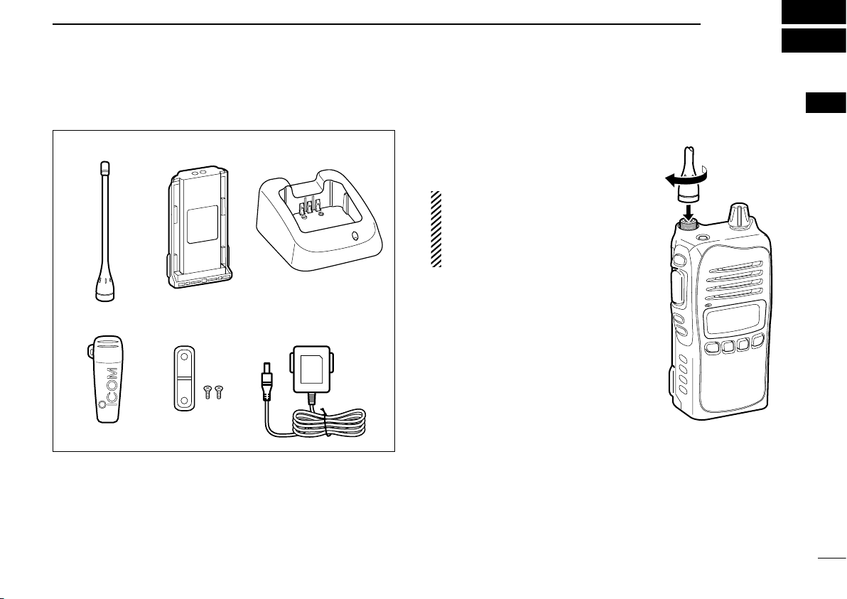
1 ACCESSORIES ............................................................................. 1–3
■Supplied accessories ..................................................................... 1
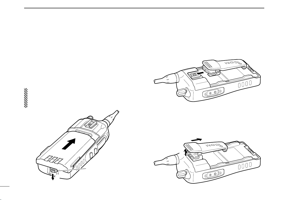
■Accessory attachments .................................................................. 1
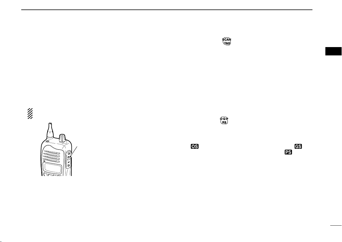
2 PANEL DESCRIPTION.................................................................. 4–9
■Front panel ..................................................................................... 4
■Function display ............................................................................. 6
■Programmable function keys .......................................................... 8
3 BASIC OPERATION.................................................................. 10–15
■Turning power ON ........................................................................ 10
■Channel selection......................................................................... 11
■Receiving and transmitting ........................................................... 11
■Priority channel setting ................................................................. 13
■ Monitor function............................................................................ 14
■ Lock function ................................................................................ 14
■ Adjusting the squelch level ........................................................... 14
■ Display backlighting......................................................................... 15
■Set mode...................................................................................... 15
4 REPEATER OPERATION................................................................ 16
■Repeater operation....................................................................... 16
■Accessing a repeater.................................................................... 16
5 SCAN OPERATION................................................................... 17–21
■Scan types.................................................................................... 17
■Scanning preparation ................................................................... 18
■Open scan.................................................................................... 19
■Group and priority scans .............................................................. 20
■Repeater search scan .................................................................. 21
6 TONE SQUELCH OPERATION................................................. 22–24
■Tone squelch operation ................................................................ 22
■Pocket beep operation.................................................................. 24
7 SELCALL OPERATION ............................................................ 25–29
■General......................................................................................... 25
■Calling operation .......................................................................... 25
■When receiving a call ................................................................... 28
■Quiet mode operation................................................................... 29
■Stun function ................................................................................ 29
8 OTHER FUNCTIONS................................................................. 30–33
■Smart-Ring and ATS (Automatic Transponder System) ............... 30
■RX frequency setting (for RX channels only)................................ 31
■Wide/Narrow function ................................................................... 33
■PTT hold function ......................................................................... 33
9 SET MODE ................................................................................ 34–38
■Set mode...................................................................................... 34
■SET mode items........................................................................... 35
10 BATTERY CHARGING .............................................................. 39–42
■Caution......................................................................................... 39
■Battery chargers........................................................................... 41
11 BATTERY CASE.............................................................................. 43
■Optional battery case (BP-240) .................................................... 43
12 OPTIONAL SWIVEL BELT CLIP .............................................. 44–45
■MB-93 contents ............................................................................ 44
■Attaching ...................................................................................... 44
■Detaching ..................................................................................... 45
13 OPTIONS......................................................................................... 46
14 SPECIFICATIONS ........................................................................... 47
15 WARRANTY AND PRODUCT REGISTRATION ....................... 48–50

1
1
ACCESSORIES
1
■Supplied accessories
Belt clip Jack cover
(with screws)
AC adapter
(for the battery charger)
Battery chargerBattery pack
Flexible antenna
■Accessory attachments
DFlexible antenna
Connect the supplied flexible an-
tenna to the antenna connector.
CAUTION:
•
NEVER HOLD the antenna
when carrying the transceiver.
• Transmitting without an antenna
may damage the transceiver.

2
1ACCESSORIES
ïBattery pack
To attach the battery pack:
Slide the battery pack in the direction of the arrow (q), then
lock it with the battery release button.
• Slide the battery pack until the battery release button makes a
‘click’ sound.
To release the battery pack:
Push the battery release button in the direction of the arrow
(w). Then slide the battery pack in the direction opposite to
the arrow (q).
NEVER release or attach the battery pack when the trans-
ceiver is wet or soiled. This may result water or dust get-
ting into the transceiver/battery pack and may result in the
transceiver being damaged.
q
w
Battery release button
DBelt clip
To attach the belt clip:
qRelease the battery pack if it is attached.
wSlide the belt clip in the direction of the arrow until the belt
clip is locked and makes a ‘click’ sound.
To detach the belt clip:
qRelease the battery pack if it is attached.
wPinch to lift the clip (q), and slide the belt clip in the di-
rection of the arrow (w).
q
w

3
1
ACCESSORIES
1
ïJack cover
Attach the jack cover when the optional speaker-microphone
or headset is not used.
To attach the jack cover:
qAttach the jack cover to the [MIC/SP] jack.
wTighten the screws using a Phillips screwdriver.
qw
[MIC/SP] jack
Jack cover
CAUTION:
Use the supplied screws only.
To detach the jack cover:
qUnscrew the screws using a Phillips screwdriver.
wDetach the jack cover for the optional speaker-microphone
or headset connection.
q
q
w

4
2PANEL DESCRIPTION
■Front panel
q
w
r
eu
i
y
Microphone
Speaker
t
o !0 !1 !2
N
: Stands for Normal mode operation.
F
: Stands for Function mode operation. (Push [Top]
(Function) to enter Function mode.)
qANTENNA CONNECTOR
Connects the supplied antenna.
w TOP KEY* [Top]
N
(Function/Set Mode)
➥Push to turn Function mode ON.
• “F” appears when Function mode is turned ON.
➥Push and hold for 2 sec. to enter Set mode. (p. 34)
F
(Function/RX VFO)
➥Push to turn the Function mode OFF.
• “F” disappears when Function mode is turned OFF.
➥Push and hold for 2 sec. to enter RX VFO mode.
(RX channel ‘RX-XX’ operation only) (p. 31)
NOTE: Returns to the Normal mode automatically after
30 sec. when no key operation is performed in Func-
tion or Set mode.
eSIDE1 KEY* [Side1]
N
(Monitor/TSQL)
➥Push to toggle the monitor function ON or OFF. (p. 14)
➥Push and hold for 2 sec. to activate the following func-
tions in order.
• Subaudible tone encoder and Tone squelch/DTCS
squelch (“T SQL” appears) (p. 23)
• Pocket beep (“T SQL ë” appears) (p. 24)
• No tone operation (“T SQL ë” disappears)
F
(SQL/ATS)
➥
Push to enter the squelch level setting mode, then push
[CH Up] or [CH Down] to set the squelch level. (p. 14)
➥Push and hold for 2 sec. to turn the ATS (automatic
transponder system) function ON or OFF. (p. 30)
Information: Up to four desired functions, one each for
Normal and Function mode, can be re-assigned to [Top],
[Side1], , , and keys with the optional CS-
41S cloning software. (p. 8)
The default setting is used in this instruction manual, for
description.

5
2
PANEL DESCRIPTION
2
rPTT SWITCH [PTT] (p. 12)
Push and hold to transmit; release to receive.
tCH UP/CH DOWN KEYS [CH UP]/[CH DOWN]
Push to select an operating channel, set mode setting,
etc. (pgs. 11, 34)
yVOLUME CONTROL [VOL] (pgs. 10, 11)
Rotate to turn the power ON/OFF and adjusts the audio
level.
uEXTERNAL MICROPHONE/SPEAKER JACK
Connect an optional speaker-microphone or headset.
NOTE: Connect or disconnect the optional equipment
after the transceiver is turned OFF.
Jack cover
NOTE: Attach the jack cover when
the optional equipment is not used.
See (p. 3) for details.
iFUNCTION DISPLAY (p. 6)
Displays a variety of information such as an operating
channel number/name, SelCall code, selected function, etc.
oSCAN/TAG KEY*
N
(Scan/Scan Tag)
➥Push to start or stop the scan. (pgs. 19, 20)
➥Push and hold for 2 sec. to set or clear the displayed
channel as a TAG (scanned) channel. (p. 18)
• “S” appears when the selected channel is tagged.
F
(TX Code CH/Call)
➥Push to enter the SelCall TX code channel selection
mode, then push [CH Up] or [CH Down] to select. (CB
channel operation only) (p. 25)
➥Push and hold for 2 sec. to transmit to the SelCall TX
code channel. (CB channel operation only) (p. 27)
!0 O•G•P/RS KEY*
N
(Scan Mode/Rpt Scan)
➥Push to select the scan type from open scan, group
scan and priority scan in order. (p. 18)
• “ ” appears when the open scan is selected, “ ” ap-
pears when the group scan is selected, and “ ” appears
when the priority scan is selected.
➥
Push and hold for 2 sec. to start the repeater scan. (p. 21)
• Repeater output channel ‘CB-R1’ to ‘CB-R8’ operation only
F
(Quiet/ID-MR)
➥Push to toggle the quiet function ON or OFF. (CB chan-
nel ‘CB-XX’ operation only) (p. 29)
• “Q” appears when the quiet function is turned ON.
➥Push and hold for 2 sec. to enter the received ID code
history indication mode. (p. 28)
• “NO ID” is displayed when no ID code is memorized.

6
2PANEL DESCRIPTION
!1 PRIO/SET•P KEY*
N
(PRIO/PRIO Set)
➥Push to select the priority channel. (p. 13)
➥Push and hold for 2 sec. to set the displayed channel
as the priority channel. (p. 13)
F
(S-Ring/PRIO Clear)
➥Push to transmit the Smart-Ring signal. (p. 30)
• When RX channel is selected, “N/A” appears.
➥Push and hold for 2 sec. to cancel the priority channel
setting. (p. 13)
!2 LOW/“ ” KEY*
N
(RF Power/Lock)
➥Push to toggle the transmit output power level. (p. 11)
➥Push and hold for 2 sec. to electronically lock all keys
except the following (p. 14):
[PTT], [Side1] (Monitor), [Top] (Function), (Call)
and (Lock)
Push and hold for 2 sec. again to turn the lock function
OFF.
F
(Dup/Zone)
➥Push to toggle the selected channel between duplex or
simplex operation. (Depending on pre-setting)
• Duplex operation can be selected in ‘CB-R1’ to ‘CB-R8’ only.
➥Push and hold for 2 sec., then select the desired zone
with [CH Up] or [CH Down]. (p. 11)
• Available only when more than two zones are set.
■Function display
q w r oiuye
!0
!1 !4 !5 !6!3!2
t
qTRANSMIT INDICATOR
Appears while transmitting.
wBUSY INDICATOR
Appears while the channel is busy.
eSIGNAL STRENGTH INDICATOR
Indicates relative signal strength level.
• “ ” blinks when the ATS function is in use. (p. 30)
rTONE INDICATORS (p. 23)
➥
“T” appears while the Subaudible tone encoder is in use.
➥“T SQL” appears while the Tone squelch/DTCS squelch
function is in use.

2
PANEL DESCRIPTION
2
tBELL INDICATOR
➥
Appears when the pocket beep function is in use. (p. 24)
➥Blinks when the specified SelCall or Smart Ring call is
received. (pgs. 28, 30)
yQUIET INDICATOR (p. 29)
Appears when the Quiet function is ON (SelCall mute is
activated.)
uPRIORITY CHANNEL INDICATOR (p. 13)
Appears when the priority channel is set.
iKEY LOCK INDICATOR (p. 14)
Appears during the key lock function is ON.
oBATTERY INDICATOR
Appears or blinks when the battery capacity decreases to
a specified level.
!0 ALPHANUMERIC DISPLAY
The operating channel number, channel name, Set mode
contents etc. is displayed.
!1 FUNCTION INDICATOR
Appears during the Function mode is ON.
• A secondary function of the key can be access.
!2 LOW POWER INDICATOR (p. 11)
Appears when low output power or dry battery mode is
selected.
• When the battery power decreases to a specified level, low
power is selected automatically.
!3 OPEN SCAN INDICATOR (p. 19)
Appears when the ‘Open scan’ is selected.
!4 GROUP SCAN INDICATOR (p. 20)
Appears when the ‘Group scan’ is selected.
!5 PRIORITY SCAN INDICATOR (p. 20)
Appears when the ‘Priority scan’ is selected.
!6 SCAN CHANNEL INDICATOR
Appears when the selected channel is specified as a tag
(scanned) channel.
Information:
“N/A” appears when the pushed key is not available.
7

8
2PANEL DESCRIPTION
■Programmable function keys
The following functions can be assigned to [Top],[Side1],
, , and programmable function keys with the
optional CS-41S cloning software.
The key function activates after pushing [Function] when
the programmable function key is assigned to the function
mode operation.
If the programmable function names are bracketed in the fol-
lowing explanations, the specific key is used to activate the
function depends on the programming.
Scan/Scan Tag
➥Push to start/stop the scan.
➥Push and hold for 2 sec. to set or clear the displayed
channel as a TAG channel.
Scan Mode/Rpt Scan
➥Push to select the scan mode.
➥Push and hold for 2 sec. to start repeater scan.
PRIO/PRIO Set
➥Push to select the priority channel.
➥Push and hold for 2 sec. to set the displayed channel as
the priority channel.
S-Ring/PRIO Clear
➥Push to transmit the Smart-Ring call.
• When RX channel is selected, “N/A” appears.
➥Push and hold for 2 sec. to cancel the priority channel set-
ting.
Monitor/TSQL
(This key function can be assigned in the Normal mode only.)
➥Push to toggle the monitor function ON or OFF.
➥Push and hold for 2 sec. to activate the following functions
in order.
• Subaudible tone encoder and Tone squelch/DTCS squelch
• Pocket beep
• No tone operation.
RF Power/Lock
➥Push to toggle the transmit output power level.
➥Push and hold for 2 sec. to toggle key lock function ON
and OFF.
TX Code CH/Call
➥Push to enter the TX code channel selection mode, then
push [CH Up] or [CH Down] to select the desired channel
(CB channel operation only).
➥Push and hold for 2 sec. to transmit the specified SelCall
TX code in the selected channel (CB channel operation
only).

2
PANEL DESCRIPTION
2
Quiet/ID-MR
➥Push to quiet function ON or OFF (CB channel operation
only).
➥Push and hold for 2 sec. to enter the received ID code his-
tory indication mode.
SQL/ATS
➥Push to enter the squelch level setting mode, then push
[CH Up] or [CH Down] to set the squelch level.
➥Push and hold for 2 sec. to turn the ATS (Automatic Tran-
sponder System) function ON and OFF.
Dup/Zone
➥Push to set the selected channel as Duplex or Simplex
operation.
• Duplex channel can be selected in ‘CB-R1’ to ‘CB-R8’ only.
➥Push and hold this key for 2 sec. then push [CH Up] or
[CH Down] to select the desired zone. (Available only
when more than two zones are set.)
Function/Set Mode
(This key function can be assigned to the [Top] key only.)
➥Push to turn Function mode ON or OFF.
➥Push and hold for 2 sec. to the Set mode ON or OFF.
•
After entering the Set mode, push this key momentarily to select
the item, and push [CH Up] or [CH Down] to change the setting.
Function/RX VFO
(This key function can be assigned to the [Top] key only.)
➥Push to turn Function mode ON or OFF.
➥Push and hold for 2 sec. to enter the RX VFO mode.
In RX VFO mode, the operating frequency and the chan-
nel spacing setting can be changed.
SQL/Set Mode
(This key function can be assigned to the [Top] key only.)
➥Push to enter the squelch level setting mode, then push
[CH Up] or [CH Down] to set the squelch level.
➥Push and hold for 2 sec. to the Set mode ON or OFF.
•
After entering the Set mode, push this key momentarily to select
the item, and push [CH Up] or [CH Down] to change the setting.
9

■Turning power ON
Prior to using the transceiver for the first time, the battery
pack must be fully charged for optimum life and operation.
(p. 39)
qRotate [VOL] to turn the power ON.
wIf the transceiver is programmed for a start up password,
input the digit codes as directed by your dealer.
• The keys in the table below can be used for password input:
• The transceiver detects numbers in the same block as identical.
Therefore “01234” and “56789” are the same.
KEY
NUMBER 0
5
4
9
3
8
2
7
1
6
[CH Down]
CH
Down
[VOL]
eWhen the “PASSWD” indication does not clear after input-
ting 4 digits, the input code number may be incorrect. Turn
the power off and start over in this case.
DBattery type selection
The battery type MUST be selected according to the type of
battery attached when turning the transceiver ON.
Ask your dealer for details.
NOTE: When the selected battery type is not matched to the
attached battery, the transceiver does not work correctly.
qTurn the power OFF in advance.
w
While pushing and holding [Top] and [PTT], rotating [VOL]
to turn power ON to toggle the attaching battery type.
• After the display appears, release [Top] and [PTT].
• “DRY” is displayed for about 3 sec. then “LOW” appears when
the Alkaline battery operation is selected. In this case, the
transmit output power is low.
• “LI-ION” is displayed for about 3 sec. when the Lithium-ion bat-
tery operation is selected.
[VOL]
[PTT]
[Top]
Appears
Alkaline battery operation
(dry battery mode) is
selected.
10
3BASIC OPERATION

11
3
BASIC OPERATION
3
■Channel selection
➥
Push [CH Up] or [CH Down] to select the desired channel.
•
While pushing and holding [CH Up] or [CH Down], the displayed
channel changes continuously until channel 1 is selected.
• When channel 1 is selected, beeps are emitted.
• ‘CB-XX’ appears when the CB channel is selected and ‘RX-XX’
appears when the RX channel is selected.
DZone type selection
(Available only when more than two zones are set.)
q
Push [Top] (Function) to enter the function mode, and push
and hold (Zone) for 2 sec. to enter the zone select mode.
wPush [CH Up] or [CH Down] to select the desired zone,
then push (Zone) again to set.
NOTE:
‘CB-05,’ ‘CB-R5’ and ‘CB-35’ channels are used for the
emergency. And ‘CB-22’ and ‘CB-23’ channels are used for
telemetry and telecommand applications, so voice communi-
cations are not available on these channels.
■Receiving and transmitting
CAUTION: Transmitting without an antenna may damage
the transceiver. See page 1 for accessory attachments.
Receiving:
qRotate [VOL] to turn the power ON.
• If “T SQL” appears on the display, push and hold [Side1] for 2
sec. once or twice to cancel the tone squelch or pocket beep.
(pgs. 23, 24)
wSelect the desired operating channel as at left.
• When receiving a signal, “ ” appears and audio is emitted
from the speaker.
• Further adjustment of [VOL] may be necessary at this point.
• Push [Side1] to toggle the monitor function ON and OFF.
ePush (RF Power) to select the output power if neces-
sary.
• “LOW” appears when low power is selected.
• Choose low power to conserve battery power, choose high
power for longer distance communications.
[VOL]
[Side1]
[CH UP]/
[CH Down]

12
3BASIC OPERATION
Transmitting:
Wait for the channel to become clear to avoid interference.
qWhile pushing and holding [PTT], speak into the micro-
phone at a normal voice level.
• “ ” appears.
• A PTT hold function is available. See p. 33 for details.
wRelease [PTT] to return to receive.
[PTT]
IMPORTANT: To maximize the readability of your signal;
1. Pause briefly after pushing [PTT].
2. Hold the microphone 5 to 10 cm from your lips, then
speak into the microphone at a normal voice level.
DTransmitting notes
• Transmit inhibit function
The transceiver has several inhibit functions which restrict
transmission under the following conditions:
- The channel is busy or un-matched CTCSS/DTCS is re-
ceived. (Depending on the transmission lockout function
setting.)
- The selected channel is a ‘receive only’ channel.
• Time-out timer
After continuous transmission for the pre-programmed time
period, the time-out timer is activated, causing the trans-
ceiver to stop transmitting.
• Penalty timer
Once the time-out timer and lockout is activated, transmis-
sion is further inhibited for a period determined by the pen-
alty timer.

13
3
BASIC OPERATION
3
■Priority channel setting
The priority channel, simply recalled by pushing (PRIO),
and also is automatically monitored during the priority scan.
You can set the only one channel as the priority channel.
“P” appears when the priority channel is set.
DThe priority channel selection
➥Push (PRIO) to select the priority channel.
• “N/A” appears when the priority channel is not set.
The priority channel
is selected.
When the priority
channel is not set.
DSet the priority channel
qSelect the desired channel. (p. 11)
wPush and hold (PRIO Set) for 2 sec. to set the dis-
played channel as the priority channel.
The selected channel is set
to the priority channel.
DCancel the priority channel setting
➥
Push [Top] (Function) to enter the function mode, then push
and hold (PRIO Clear) for 2 sec. to cancel the priority
channel setting.
• “P” disappears.
The priority channel
is cancelled.

14
3BASIC OPERATION
■Monitor function
This function is used to listen to weak signal or to open the
tone squelch manually.
➥Push [Side1] (Monitor) to toggle the monitor function ON
and OFF.
• “ ” blinks when the monitor function is in use.
Blinks
■Lock function
This function electronically locks all keys except for [PTT],
[Side1] (Monitor), [Top] (Function), (Call) and (Lock) to
prevent accidental channel changes and function access.
➥Push and hold (Lock) for 2 sec. to toggle the lock func-
tion ON and OFF.
• “ ” appears when the lock function is in use.
Appears
■Adjusting the squelch level
In order to receive signals properly, the squelch must be ad-
justed to the proper level.
q
Push [Top] (Function) to enter the function mode, then push
[Side1] (SQL) to enter the squelch level setting mode.
wPush [CH Up] or [CH Down] to adjust the squelch level
within 0 to 9 ranges.
ePush [Side1] (SQL) to exit the squelch level setting mode.
The squelch level
is indicated.

15
3
BASIC OPERATION
3
■Display backlighting
The transceiver has display backlight for night-time operation.
qPush and hold [Top] (Set Mode) for 2 sec. to enter set
mode.
wPush [Top]* several times until “LIGHT” appears.
ePush [CH Up] or [CH Down] to select the display back-
light condition.
• ON : Backlight lights continuously.
• A2 : Lights for 5 sec. when any key except [PTT] is pushed, or
the LCD indication is changed.
• AT : Lights for 5 sec. when any key except [PTT] is pushed or
the Selcall signal is transmitted/received.
• OF : Backlight never lights.
rRotate [VOL] to turn the power OFF, or push and hold
[Top] (Set Mode) for 2 sec. to exit set mode.
*Regardless of the assigned key function.
■Set mode
Set mode is accessed at power ON and allows you to set
seldom-changed settings. In this case you can “customize”
the transceiver operation to suit your preferences and oper-
ating style. See p. 34 for set mode items detail.
Entering the set mode:
qWhile pushing and holding [CH Up] and [CH Down],
rotate [VOL] to turn the power ON. Then, push and hold
[Top] (Set Mode) for 2 sec. to enter set mode.
wPush [Top]* several times to select the appropriate item.
Then push [CH Up] or [CH Down] to set the desired
level/condition.
• Available set mode functions are SQL Level, CTCSS tone/
DTCS code, Auto power OFF, Backlight, Beep, Beep Level,
Mic Gain, Battery Voltage, Signal Moni, Power Save, TOT,
Lock-out, Scan Stop Timer, Scan Restart, Roger Beep and
Own ID.
eRotate [VOL] to turn the power OFF, or push and hold
[Top] (Set Mode) for 2 sec. to exit set mode.
NOTE: Set mode can be accessed via the [Top] (Set
Mode) key operation only (p. 34.) In this case, set mode
allows quicker item selection. Set “Enable” to the most
often used items with the CS-41S cloning software.
*Regardless of the assigned key function.
[

16
4REPEATER OPERATION
■Repeater operation
Repeaters allow you to extend the operational range of your
radio.
Normally, a repeater has independent frequencies for re-
ceive and transmit.
Station BStation A
Repeater
476.4250 MHz
477.1750 MHz 477.1750 MHz
476.4250 MHz
Uplink
(transmitting freq.)
Downlink
(receiving freq.)
■Accessing a repeater
A repeater amplifies received signals and re-transmits them
on a different frequency, allowing you to communicate over
greater distances with improved reliability. When using a
repeater, the repeater output channel (‘CB-R1’ to ‘CB-R8’)
must be selected.
You can search the accessible repeater in your local area
using the Repeater search scan function (p. 21).
qSelect the desired repeater output channel (‘CB-R1’ to
‘CB-R8’). (p. 11)
wWhile pushing and holding [PTT], speak into the micro-
phone at your normal voice level.
• “ ” appears.
Appears
eRelease [PTT] to receive.
Other manuals for IC-41S
2
Table of contents
Other Icom Transceiver manuals