Icom IC-78 User manual

INSTRUCTION MANUAL
HF TRANSCEIVER
i78
This device complies with Part 15 of the FCC rules. Operation is sub-
ject to the following two conditions: (1) This device may not cause
harmful interference, and (2) this device must accept any interference
received, including interference that may cause undesired operation.

IMPORTANT
READ THIS INSTRUCTION MANUAL
CAREFULLY before attempting to operate the
transceiver.
SAVE THIS INSTRUCTION MANUAL. This
manual contains important safety and operating in-
structions for the IC-78.
EXPLICIT DEFINITIONS
i
PRECAUTIONS
RWARNING HIGH VOLTAGE! NEVER at-
tach an antenna or internal antenna connector during
transmission. This may result in an electric shock or
burn.
RNEVER apply AC to the [DC13.8V] jack on the
transceiver rear panel. This could cause a fire or ruin
the transceiver.
RNEVER apply more than 16 V DC, such as a 24 V
battery, to the [DC13.8V] jack on the transceiver rear
panel. This could cause a fire or ruin the transceiver.
RNEVER let metal, wire or other objects touch any
internal part or connectors on the rear panel of the
transceiver. This may result in an electric shock.
NEVER expose the transceiver to rain, snow or any
liquids.
AVOID using or placing the transceiver in areas with
temperatures below –10°C (+14°F) or above +60°C
(+140°F). Be aware that temperatures on a vehicle’s
dashboard can exceed +80°C (+176°F), resulting in
permanent damage to the transceiver if left there for
extended periods.
AVOID placing the transceiver in excessively dusty
environments or in direct sunlight.
AVOID placing the transceiver against walls or putting
anything on top of the transceiver. This will obstruct
heat dissipation.
During mobile operation, DO NOT operate the trans-
ceiver without running the vehicle’s engine. When the
transceiver power is ON and your vehicle’s engine is
OFF, the vehicle’s battery will soon become exhaust-
ed.
Make sure the transceiver power is OFF before start-
ing the vehicle. This will avoid possible damage to the
transceiver by ignition voltage spikes.
During maritime mobile operation, keep the
transceiver and microphone as far away as possible
from the magnetic navigation compass to prevent
erroneous indications.
BE CAREFUL! The heatsink will become hot when
operating the transceiver continuously for long
periods.
BE CAREFUL! If a linear amplifier is connected, set
the transceiver’s RF output power to less than the
linear amplifier’s maximum input level, otherwise, the
linear amplifier will be damaged.
Use Icom microphones only (supplied or optional).
Other manufacturer’s microphones have different
pin assignments, and connection to the IC-78 may
damage the transceiver.
WORD DEFINITION
RWARNING Personal injury, fire hazard or electric
shock may occur.
CAUTION Equipment damage may occur.
NOTE Inconvenience only. No risk of per-
sonal injury, fire or electric shock.

1
1
TABLE OF CONTENTS
q
w
er
IMPORTANT .............................................................. i
EXPLICIT DEFINITIONS............................................ i
PRECAUTIONS.......................................................... i
1 TABLE OF CONTENTS ........................................ 1
SUPPLIED ACCESSORIES...................................... 1
2 PANEL DESCRIPTION ................................... 2 – 7
nFront panel ......................................................... 2
nFunction display ................................................. 4
nRear panel.......................................................... 5
nMicrophone (HM-36) .......................................... 7
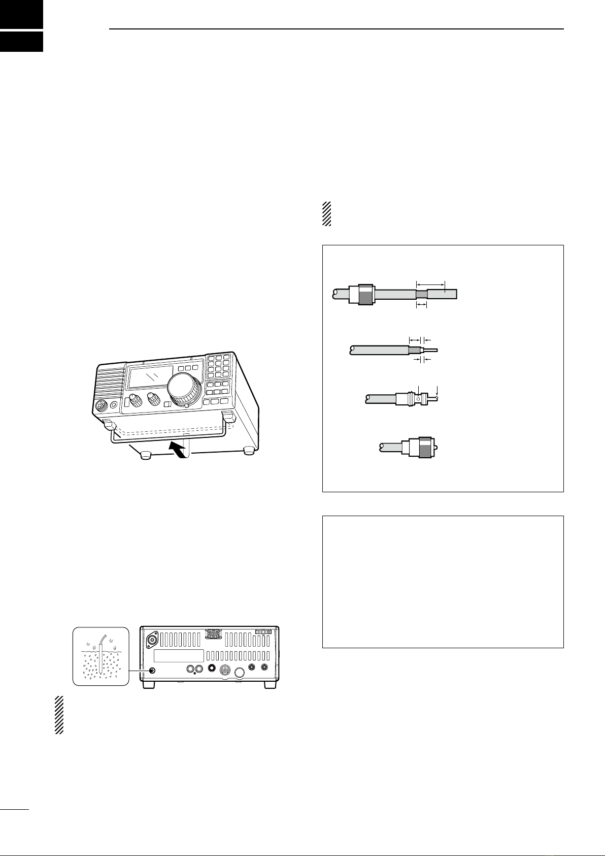
3 INSTALLATION AND CONNECTIONS ........ 8 – 12
nUnpacking .......................................................... 8
nSelecting a location ............................................ 8
nGrounding .......................................................... 8
nAntenna connection ........................................... 8
nRequired connections ........................................ 9
nPower supply connections ............................... 10
nAdvanced connections ..................................... 11
nExternal antenna tuners ................................... 12
4 OPERATION................................................. 13– 27
nSelecting a channel.......................................... 13
nFrequency indication ........................................ 14
nLock function .................................................... 14
nScan function ................................................... 14
nBasic voice receive and transmit...................... 15
nMode selection ................................................. 15
nRF gain and Squelch........................................ 15
nFunctions for transmit....................................... 16
nFunctions for receive........................................ 19
nFilter selection .................................................. 21
nFilter setting...................................................... 22
nFunctions for CW ............................................. 23
nFunctions for RTTY .......................................... 25
nChannel comment programming...................... 27
5 SET MODE ................................................... 28– 33
nGeneral ............................................................ 28
nQuick set mode items....................................... 29
nInitial set mode items ....................................... 31
6 EXTRA FEATURES ..................................... 34– 36
nInstruction......................................................... 34
nVFO operation.................................................. 34
n2-Tone alarm operation.................................... 36
7 INSTALLATION AND CONNECTIONS ....... 37– 38
nOpening the transceiver’s case........................ 37
nOptional bracket and carrying handle .............. 37
nCR-338 HIGH STABILITY CRYSTAL UNIT .......... 38
nOptional IF filters .............................................. 38
8 MAINTENANCE ........................................... 39– 40
nTroubleshooting ............................................... 39
nFuse replacement ............................................ 40
nResetting the CPU ........................................... 40
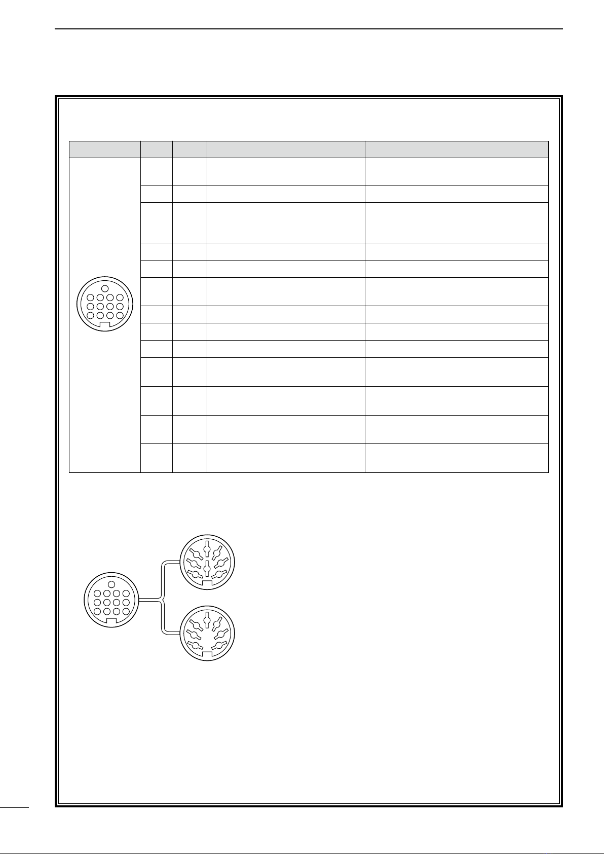
9 REMOTE JACK INFORMATION ................. 41– 42
nCI-V remote control .......................................... 41
nData cloning between transceivers .................. 42
10 SPECIFICATIONS ............................................ 43
12 OPTIONS ................................................... 44– 45
SUPPLIED ACCESSORIES
The transceiver comes with the following accessories.
Qty.
q DC power cable .................................................... 1
w Hand microphone (HM-36) ................................... 1
e Fuse (FGB 20 A; for DC cable)............................. 1
r Fuse (FGB 4 A; internal use) ................................ 1

nFront panel
qPOWER SWITCH [PWR]
➥Push momentarily to turn power ON.
• Turn the optional DC power supply ON in advance.
➥Push for 1 sec. to turn power OFF.
➥While pushing and holding [SET], push [PWR] to
enter the initial set mode. (p. 28)
wMICROPHONE CONNECTOR [MIC]
Accepts supplied or optional microphone.
• See p. 45 for appropriate microphones.
• See p. 7 for microphone connector information.
eHEADPHONE JACK [PHONES] (p. 11)
Accepts headphones.
• When headphones are connected, the internal
speaker or connected external speaker does not
function.
rAF CONTROL [AF] (inner control)
Varies the audio output level from the speaker.
tRF GAIN/SQUELCH CONTROL [RF/SQL]
(outer control; pgs. 15, 31)
Adjusts the squelch threshold level. The squelch re-
moves noise output from the speaker (closed con-
dition) when no signal is received.
• The squelch is available for all modes.
• The control can be set as the squelch plus RF
gain controls or squelch control only (RF gain is
fixed at maximum) in initial set mode.
yRIT CONTROL [RIT] (inner control; p. 19)
➥Shifts the receive frequency ±1.2 kHz for clear
reception of an off frequency signal.
• Rotate the control clockwise to increase the fre-
quency, or rotate the control counterclockwise to
decrease the frequency. “ ” appears on the
display.
uIF SHIFT CONTROLS [SHIFT]
(outer control; p. 20)
Shifts the center frequency of the receiver’s IF
passband.
• Rotate the control clockwise to shift the center fre-
quency higher, or rotate the control counterclock-
wise to shift the center frequency lower.
iLOCK SWITCH [LOCK] (p. 14)
Push momentarily to turn the dial lock function ON
and OFF.
• The dial lock function electronically locks the
channel selector.
oCHANNEL SELECTOR
Selects an operating channel, sets conditions in the
quick/initial set mode items, etc.
!0 PREAMP SWITCH [P.AMP] (p. 19)
Push to turn the preamp ON or OFF.
!1 FC SWITCH [CH]
➥Push to change the indication, channel comment
or stored frequency. (p. 14)
*This key action only for some versions.
➥
Push for 1 sec. to entering into VFO mode. (p. 35)
!2 MEMORY CHANNEL UP/DOWN SWITCHES
[√DN]/[UP ∫]
➥Push to select the operating channel. (p. 13)
➥Push for 1 sec. to start scanning. (p. 14)
➥Push to select the quick/initial set mode items
while quick/initial set mode is selected. (p. 28)
➥Push to select the digit of channel comment
while editing. (p. 27)
2
2
PANEL DESCRIPTION
PWR
Speaker Function Display @1 @0 !9 !7
!5
!4
!6
!3
!2
!0
!8
!1
o
iuytre
w
q

3
2
PANEL DESCRIPTION
!3 ATTENUATOR SWITCH [ATT] (p. 19)
Push to turn the 20 dB attenuator function ON and
OFF.
!4 TUNER SWITCH [TUNER] (p. 18)
➥Push to turn the antenna tuner function ON and
OFF.
➥Push for 1 sec. to manually tune the tuner.
• An optional antenna tuner must be connected.
•
When the tuner cannot tune the antenna, the tun-
ing circuit is bypassed automatically after 20 sec.
!5 SET SWITCH [SET]
➥Push for 1 sec. to enter the quick set mode.
(p. 28)
➥Push and hold [SET], then push [PWR] to enter
the initial set mode. (p. 28)
➥Push to change the meter function; (p. 16)
• PO: indicates the relative RF output power.
• ALC: Indicates ALC level.
• SWR: Indicates the SWR over the transmission
line.
!6 MIC COMPRESSOR SWITCH [COMP] (p. 17)
Turn the Mic. compressor function ON and OFF.
!7 KEYPAD
The keypad can be used for several functions as
described below:
➥[0] to [9]
— For entering operating channel number. (p. 13)
— Selects a character during channel comment
programming. (p. 27)
➥[ENT]
— Direct channel number input. (p. 13)
➥[TXF]
— Transmit frequency indication. (p. 14)
— Selects a space and changes the editing digit
during channel comment programming. (p. 27)
!8 NOISE BLANKER SWITCH [NB] (p. 19)
➥Turns the noise blanker ON and OFF. The noise
blanker reduces pulse-type noise such as that
generated by automobile ignition systems. This
function is not effective against non pulse-type
noise.
➥Push [NB] for 1sec. to enter the noise blanker
level setting condition.
!9 TONE SWITCH [TONE]
*
This key action may differ according to version.
➥Selects the call channel and emits a distress
alarm tone from the speaker. (p. 36)
➥Transmits a distress alarm or alarm testing sig-
nal when pushed for 1 sec. (p. 36)
• Cancel the distress alarm tone emission, or dis-
tress alarm transmission.
➥Selects the tuning step item in the quick set
mode directly.
➥No function is assigned.
@0 CALL SWITCH [CALL]
➥Push to select call channel.
• Push again to return to previous condition.
@1 MODE SWITCH [MODE] (p. 15)
Push to change an operating mode.
• Push [MODE] for 1 sec. during SSB mode to
switch between LSB or USB.
• Push [MODE] for 1 sec. during CW or RTTY
mode, to switch between CW and CW reverse or
RTTY and RTTY reverse. “ ” appears on the
display.

4
2PANEL DESCRIPTION
nFunction display
qLOCK INDICATOR (p. 14)
Appears when the dial lock function is in use.
wRECEIVE INDICATOR
Appears while receiving a signal or when the
squelch is open.
eTUNE INDICATOR
➥Appears or disappears when the connected au-
tomatic tuner is tuned completely, depending on
connected antenna tuner type.
➥Flashes while tuning.
rTRANSMIT INDICATOR
➥Appears while transmitting.
➥Flashes while transmit frequency is indicated.
tALARM INDICATOR
*This indicator appears only some versions.
Appears while 2-tone alarm is emitting or transmit-
ting
yFUNCTION INDICATORS
➥“P.AMP” appears when preamp is activated.
➥“ATT” appears when the RF attenuator is activat-
ed.
➥“NB” appears when the Noise Blanker is activat-
ed.
➥“BK” appears when the semi break-in function is
selected in quick set mode.
➥“F-BK” appears when the full break-in function
activates in CW mode. (p. 23)
➥“VOX” appears when the VOX function is select-
ed in quick set mode.
➥“COM” appears when the speech compressor
activates in SSB mode.
➥“SCAN” appears during scanning.
• Flashes when scan is paused.
uSIGNAL/SQL/RF-GAIN METER
➥Functions as an S-meter while receiving.
➥Functions as a Power, ALC or SWR meter while
transmitting. (p. 16)
iVFO/MEMORY INDICATOR
➥“MEMO” appears during regular operation.
*This indicator appears only some versions.
➥“VFO” appears during VFO operation.
oCHANNEL NUMBER READOUT (p. 13)
Shows the selected channel number.
!0 BLANK INDICATOR
Appears when no frequency programmed channel
is selected.
!1 SPLIT INDICATORS (p. 13)
Appears when the duplex channel, in which differ-
ent frequencies between transmit and receive are
programmed, is selected.
!2 RIT INDICATOR (p. 19)
Appears when the RIT function is in use.
!3 CHANNEL READOUT
Shows the memory names, or stored frequency of
the selected channel.
!4 REVERSE INDICATOR (p. 15)
Appears when the CW reverse or RTTY reverse
mode is selected.
!5
WIDE/NARROW FILTER INDICATORS (pgs. 21, 22)
➥
“ ” appears when the wide IF filter is selected.
➥“ ” appears when the narrow IF filter is select-
ed.
!6 MODE INDICATORS (p. 15)
Indicates the temporarily selected operating mode.
!6 !4
!5
uoi
r
e
w
!0
!3
!1
t
y
q
!2

5
2
PANEL DESCRIPTION
nRear panel
qANTENNA TERMINAL [ANT] (p. 9)
Connects a 50 Ωantenna with a PL-259 connector
and a 50 Ωcoaxial cable.
wDC POWER SOCKET [DC 13.8V] (p. 10)
Accepts 13.8 V DC through the supplied DC power
cable.
eTUNER CONTROL SOCKET [TUNER] (p. 11)
Accepts the control cable from an optional antenna
tuner.
rREMOTE JACK [REMOTE] (p. 11)
For use with a personal computer for remote oper-
ation of transceiver functions, and data cloning be-
tween transceivers.
tEXTERNAL SPEAKER JACK [EXT SP]
Connects an 8 Ωexternal speaker, if desired.
• When an external speaker is connected, the inter-
nal speaker does not function.
yACCESSORY SOCKET [ACC] (p. 6)
Enables connection to external equipment such as
a TNC for data communications or a linear amplifi-
er, etc.
uELECTRONIC KEYER JACK [KEY]
Accepts a paddle to activate the internal electronic
keyer.
• Selection between the internal electronic keyer
and straight key operation can be made in initial
set mode.
iALC INPUT JACK [ALC]
Connects to the ALC output jack of a non-Icom lin-
ear amplifier.
oSEND CONTROL JACK [SEND]
Goes to ground while transmitting to control exter-
nal equipment such as a linear amplifier.
• Max. control level: 16 V DC/2 A
!0 GROUND TERMINAL [GND] (p. 9)
Connects the terminal to ground.
q w e
rtyuio!
0
Rear panel view
When connecting
a straight key
When connecting
a paddle
(dot)
(com)
(dash)
(⊕)

6
2PANEL DESCRIPTION
D ACC SOCKET INFORMATION
• ACC socket
• When connecting the ACC conversion cable (OPC-599)
ACC PIN # NAME DESCRIPTION SPECIFICATIONS
ACC 1
ACC 2
FSKK
AF
GND
SQLS
SEND
13.8 V
MOD
ALC
8 V
ALC
GND
NC
SEND
13.8 V
BAND
1
1
2
2
3
3
4
4
8
8
7
7
6
6
5
5
9
10 11 12
13
1
2
3
4
76
5
Rear panel
view
1 2 3 4
8765
9
10 11 12
13
1 8 V Regulated 8 V output. Output voltage : 8 V ±0.3 V
Output current : Less than 10 mA
2 GND Connects to ground. —
Input/output pin. Ground level : –0.5 V to 0.8 V
3 SEND Goes to ground when transmitting. Input current : Less than 20 mA
When grounded, transmits.
4 BDT Data line. —
5 BAND Band voltage output.
6 ALC ALC voltage output. Control voltage : –4 V to 0 V
Input impedance
: More than 10 kΩ
7 NC — — —
8
13.8 V
13.8 V output when power is ON. Output current : Max. 1 A
9 TKEY Key line. —
10 FSKK RTTY key input. Ground level : –0.5 V to 0.8 V
Input current : Less than 10 mA
11 MOD Modulation input.
Input impedance
: 10 kΩ
Input level : Approx. 100 mV rms
12 AF AF detector output.
Output impedance
: 4.7 kΩ
Fixed, regardless of [AF] position. Output level : 100–300 mV rms
13 SQLS Squelch output. SQL open : Less than 0.3 V/5 mA
Goes to ground when squelch opens.
SQL closed :
More than 6.0 V/100 µA

7
2
PANEL DESCRIPTION
nMicrophone (HM-36)
• DESCRIPTION
qUP/DOWN SWITCHES [UP]/[DN]
Change the selected readout frequency or memory
channel.
• Continuous pushing changes the frequency or
memory channel number continuously.
• The [UP]/[DN] switch can simulate a key paddle.
Preset in the CW PADDL in initial set mode. (p. 32)
wPTT SWITCH
Push and hold to transmit; release to receive.
• MICROPHONE CONNECTOR
(Front view)
CAUTION: DO NOT short pin 2 to ground as this
can damage the internal 8 V regulator.
q
w
yGND (PTT ground)
tPTT
rMain readout squelch switch
qMicrophone input
w+8 V DC output
eFrequency up/down
uGND
(Microphone ground)
iMain readout AF output
(varies with [AF])
• HM-36 SCHEMATIC DIAGRAM
[MIC] FUNCTION DESCRIPTION
Pin No.
w+8 V DC output Max. 10 mA
eFrequency up Ground
Frequency down Ground through 470 Ω
rSquelch open “Low” level
Squelch closed “High” level
+
q
w
ert
y
u
i
4700 pF
0.33 µF
Microphone
MIC
ELEMENT
22 kø
470 ø
DOWN UP
PTT
RECEIVE
TRANSMIT
Microphone Cable
Microphone Plug
1 kø
+
10 µF

3
8
INSTALLATION AND CONNECTIONS
nAntenna connection
For radio communications, the antenna is of critical im-
portance, along with output power and sensitivity. Select
antenna(s), such as a well-matched 50 Ωantenna, and feed
line. 1.5:1 or better of Voltage Standing Wave Ratio (VSWR)
is recommended for your desired band. Of course, the trans-
mission line should be a coaxial cable.
CAUTION: Protect your transceiver from light-
ning by using a lightning arrestor.
nUnpacking
After unpacking, immediately report any damage to
the delivering carrier or dealer. Keep the shipping car-
tons.
For a description and a diagram of accessory equip-
ment included with the IC-78, see ‘Supplied accesso-
ries’ on p. 1 of this manual.
nSelecting a location
Select a location for the transceiver that allows ade-
quate air circulation, free from extreme heat, cold, or
vibrations, and away from TV sets, TV antenna ele-
ments, radios and other electro-magnetic sources.
The base of the transceiver has an adjustable stand
for desktop use. Set the stand to one of two angles de-
pending on your operating conditions.
nGrounding
To prevent electrical shock, television interference
(TVI), broadcast interference (BCI) and other prob-
lems, ground the transceiver through the GROUND
terminal on the rear panel.
For best results, connect a heavy gauge wire or strap
to a long earth-sunk copper rod. Make the distance
between the [GND] terminal and ground as short as
possible.
RWARNING: NEVER connect the [GND]
terminal to a gas or electric pipe, since the connec-
tion could cause an explosion or electric shock.
Antenna SWR
Each antenna is tuned for a specified frequency
range and SWR may be increased out-of-range.
When the SWR is higher than approx. 2.0:1, the
transceiver’s power drops to protect the final transis-
tor. In this case, an antenna tuner is useful to match
the transceiver and antenna. Low SWR allows full
power for transmitting even when using the antenna
tuner. The IC-78 has an SWR meter to monitor the
antenna SWR continuously.
PL-259 CONNECTOR INSTALLATION EXAMPLE
30 mm ≈9⁄8in 10 mm ≈3⁄8in 1–2 mm ≈1⁄16 in
30 mm
10 mm (soft solder)
10 mm
1–2 mm
solder solder
Soft
solder
Coupling ring
Slide the coupling ring
down. Strip the cable
jacket and soft solder.
Slide the connector
body on and solder it.
Screw the coupling
ring onto the connec-
tor body.
Strip the cable as
shown at left. Soft
solder the center con-
ductor.
q
w
e
r

9
3
INSTALLATION AND CONNECTIONS
nRequired connections
PWR
MICROPHONES (p. 45)
SM-20 or SM-6
HM-36
GROUND (p. 8)
Use the heaviest gauge wire
or strap available and make
the connection as short as
possible.
Grounding prevents electrical
shocks, TVI and other prob-
lems.
ANTENNA
[Example]: 1.8–30 MHz bands
DC POWER SUPPLY
PS-125
CW KEY
A straight key can be used when the
internal electronic keyer is turned
OFF in “CW PADDL” in initial set
mode. (p. 32)
AH-710
• Front panel
• Rear panel

10
3INSTALLATION AND CONNECTIONS
nPower supply connections
Use an optional PS-125 dc power supply when oper-
ating the IC-78 with AC power. Refer to the diagrams
below.
CAUTION:
Before connecting the DC power cable,
check the following important items. Make sure:
• The [PWR] switch is OFF.
• Output voltage of the power source is 12–15 V
when you use a non-Icom power supply.
• DC power cable polarity is correct.
Red : positive +terminal
Black : negative _terminal
CONNECTING A VEHICLE BATTERY
12 V
battery
Supplied
DC power cable
+red
_black Crimp
Solder
Grommet
NEVER connect to
a 24 V battery.
NOTE: Use terminals for
the cable connections.
CONNECTING NON-ICOM DC POWER SUPPLY
DC power
socket
DC power supply AC outlet
AC cable
20 A fuses
Supplied
DC power cable
13.8 V 21 A
_+
black
red
+
_
CONNECTING PS-125 DC POWER SUPPLY
PS-125
Connect to an AC outlet
using the supplied AC cable.
DC power
socket

3
INSTALLATION AND CONNECTIONS
11
nAdvanced connections
PWR
MIC
The AFSK modulation signal can be
input from [MIC]. (p. 25)
HEADPHONES
• Front panel
ANTENNA
Connects a linear amplifier, etc.
[REMOTE] (pgs. 41, 42)
Used for computer control and transceive operation,
and cloning operation between transceivers.
[SEND], [ALC]
Used for connecting a
non-Icom linear ampli-
fier.
EXTERNAL SPEAKER (p. 44)
SP-21, etc.
ACC SOCKETS (p. 6)
AT-120,
AT-130, or
AH-4 (p. 44)
AH-2b
or long wire
with
• Rear panel

3INSTALLATION AND CONNECTIONS
12
nExternal antenna tuners
CONNECTING AN ANTENNA TUNER (p. 44)
Coaxial cable (from the tuner)
Long wire or optional AH-2b
Ground
IC-78 AT-120/AT-130/AH-4
Control cable
Ground

4
OPERATION
13
nSelecting a channel
The transceiver has 99 memory channels. However,
the number of channels can be restricted in initial set
mode (p. 32) depending on your needs. A total of 3
ways of channel selections are available to suit your
operating style.
DUsing the channel selector
Rotate the channel selector clockwise (channel num-
ber increases) or counterclockwise (channel number
decreases) to select desired channel.
This is the most useful way of channel selection.
DUsing up/down switches
Push [√DN]/[UP ∫] on the front panel or the micro-
phone to select the desired channel.
This way is convenient when changing a small num-
ber of channels.
• When a duplex channel (different frequencies be-
tween transmit and receive) is selected, “ ” ap-
pears.
DUsing the keypad
Enter the number of the desired channel number using
the keypad (0 to 9), then push [ENT].
This way is convenient for remembering the usage
and stored channel number, or when changing large a
number of channels.
• When a duplex channel (different frequencies be-
tween transmit and receive) is selected, “ ” ap-
pears.
• When a blank channel (no frequency is programmed)
is selected, “ ” appears.
Channel 1
Channel 2
Channel 99
Rotate the
channel selector
Push [ZDN]/[UP Y]
switch
to select a
channel
or
• Example 1— selecting channel 8
Push Push
Push Push
Blinks
• Example 2— selecting channel 25
Push
Blinks Blinks

4OPERATION
14
nFrequency indication
By pushing the [FC], channel comment indication or
frequency indication can be selected.
DTransmit frequency indication
By pushing the [TXF], transmit frequency is indicat-
ed, regardless channel comment or frequency indi-
cation.
While transmit frequency is indicated, “ ” flashes.
nLock function
The lock function electronically locks the main dial to
prevent accidental channel changing.
Push [LOCK] to turn the lock function ON and OFF.
Before channel selection, turn this function OFF.
nScan function
Scan function repeatedly scans programmed chan-
nels. This function is convenient to wait for calls on
multiple channels.
qSet [RF/SQL] control at the center (12 o’clock)
position (opening squelch), then rotate [RF/SQL]
control clockwise to the position where the noise
disappears.
wPush [√DN] or [UP ∫] for 1 sec. to start chan-
nel scan.
• The “SCAN” indicator appears.
eWhen a signal is received, channel scan pauses
on that channel.
rPush [√DN] or [UP ∫] to cancel channel scan.
NOTE: The scan resume condition (the action
after signal receiving) can be selected as “scan
resume” or “scan cancel” in the initial set mode
(p. 31).
[ZDN]/[UP Y]
switches
Appears while lock function is activated.
Appears while
scanning.
ch 5
ch 2 ch 3 ch 4
ch 6ch 7
BLANK
BLANK
ch 1
ch 99
Shallow
Deep
Recommended
position
Squelch control
Channel indication
Frequency indication
Push
Push
Push
Transmit frequency indication
Flashes

15
4
OPERATION
nMode selection
The [RF/SQL] control adjusts either the RF gain or
the squelch. The action depends on the operating
mode and the condition of the RF/SQL item in initial
set mode (p. 31).
• [RF/SQL] control priority
* The RF gain is set to maximum level when the [RF/SQL]
is set as [SQL] control.
The RF gain is used to adjust the receiver gain.
• Shallow rotation moves the S-meter to the right indicating
the signal strength which can be received.
The recommended position for RF gain is the 12
o’clock position since this sets RF gain to the max.
The SQUELCH removes noise output from the
speaker (closed condition) when no signal is received.
The squelch is available for the other modes.
• A segment appears in the S-meter to indicate the S-meter
squelch level.
• When set as the [RF/SQL] control
• When set as the [SQL] control
• When set as the [RF] control
nRF gain and Squelch
Set mode setting SSB, CW, RTTY AM
rS (RF/SQL) RF/SQL RF/SQL
At (Auto) RF gain SQL*
Sq (SQL) SQL* SQL*
(default)
RF gain adjustable
range
Maximum RF gain
Squelch is open.
S-meter squelch
S-meter squelch
threshold
Squelch is open. S-meter squelch
S-meter squelch
threshold
Shallow Deep
Minimum RF gain
Adjustable range
Maximum RF gain
nBasic voice receive and transmit
qCheck the following in advance:
➥Microphone is connected.
➥[AF] control is set to minimum position.
➥
[RF/SQL] is set to center position (squelch open).
➥[RIT] control set to center position.
w
Selects the desired channel to be received with the
channel selector, [√DN]/[UP ∫], or 10-key pad.
•
The S-meter shows signal strength when signal is received.
eAdjust [AF] to the desired audio level when receiv-
ing a signal.
rPush [MODE] to select the desired operation mode,
if the received signal is in a different mode.
tIf the bass or treble of the receive audio is too
strong, rotate [RIT] control to obtain clear audio.
(p. 19)
y
Push [TUNER] to tune the antenna tuner, if connected.
• “TUNE” indicator flashes for 1 to 2 sec. for the first tun-
ing on a channel.
uPush and hold [PTT] on the microphone, and speak
into the microphone at a normal voice level.
• The RF meter shows the output power according to
your voice level, when RF power meter is selected.
iRelease [PTT] to return to receive.
[RIT]
[AF]
[RF/SQL]
Microphone
connector
The following modes are available in the IC-78:
SSB (LSB/USB), CW, CW REV (CW reverse), RTTY,
RTTY REV (RTTY reverse) and AM.
➥Push [MODE] to select desired operation mode.
➥Push [MODE] for 1 sec. to change between USB
and LSB, CW and CW reverse or RTTY and RTTY
reverse. (SSB, CW and RTTY mode only)
• The selected mode is indicated in the function display.
Note: The selected mode can be used for temporary
operation only.
OPERATING MODE SELECTION
Push
momentarily
Push
for 1 sec.
USB LSB
CW CW
RTTY RTTY
AM
MODE
MODE

16
4OPERATION
ïMeter function
The bar meter in the function display acts as an S-
meter (for relative signal strength) during receive
and can be selected for one of three functions dur-
ing transmit.
• Push [SET] to select the PO, ALC and SWR meter
mode.
• Measuring SWR
qConfirm that the output power is over 30 W.
w Push [SET] to select the SWR meter.
e Push [MODE] to select CW or RTTY operation.
• Key down or push [PTT] to transmit; then read
the actual SWR from the meter:
≤1.5; well matched antenna
≥1.5; check antenna or cable connection, etc.
Display Measurement
Indication
PO Indicates the relative RF output power.
ALC
Indicates the ALC level. When the meter
movement shows the input signal level ex-
ceeds the allowable level, the ALC limits the
RF power. In such cases, reduce the micro-
phone gain (see above).
SWR
Indicates the SWR over the transmission line
.
nFunctions for transmit
ïOutput power and microphone gain
• Setting output power
qPush [SET] for 1 sec. to select quick set mode.
wPush [ZDN]/[UP Y] to select “RF POWER”.
eRotate the main dial to select the desired output.
• Output power is displayed in 101 steps (L, 1–99 and
H) but is continuously selectable.
• Available power
SSB/CW/RTTY: 2 (or less) to 100 W
AM: 2 (or less) to 35 W*
*Carrier power
Maximum output
power is selected.
• Setting microphone gain
Microphone gain must be adjusted properly so that
your signal does not distort when transmitted.
qSelect SSB or AM mode.
wPush [SET] for 1 sec. to enter the quick set mode.
ePush [ZDN]/[UP Y] to select “MIC GAIN”.
rAdjust the mic gain while speaking into the micro-
phone, so that the ALC meter does not exceed the
ALC zone.
tPush [SET] to exit quick set mode.
Microphone gain is
set to 50.
ALC zone
The best match is in this range.

17
4
OPERATION
ïMicrophone compressor
IC-78 has a built-in, low distortion Mic compressor cir-
cuit. This circuit increases your average talk power in
SSB mode and is especially useful when the receiv-
ing station is having difficulty copying your signal.
qSelect USB or LSB mode.
wPush [COMP] switch to turn mic compressor ON.
• “COM” indicator appears.
eConfirm the ALC level.
• Push [SET] to select the ALC meter.
• Speak into the microphone at a normal voice level.
• If the ALC meter peak past the ALC zone, re-adjust the
mic. gain. (p. 16)
• Be sure the mic gain is in the range of 20 to 50.
Note: When the ALC meter peaks above the ALC
zone, your transmitted voice may be distorted.
The VOX (Voice-operated Transmission) function
switches between transmit and receive with your
voice. This function provides an opportunity to input
log entries into your computer, etc. while operating.
qSelect “VOX” in quick set mode.
• Push [SET] for 1 sec. to select quick set mode.
• Push [ZDN]/[UP Y] to select “VOX”.
wRotate the channel selector to turn VOX function
ON.
eSelect “VOX GAIN” in quick set mode.
• Push [ZDN]/[UP Y] to select “VOX”.
rWhile speaking into the microphone, adjust [VOX
GAIN] with the channel selector, until the trans-
ceiver is transmitting.
tSelect “VOX DELY” in quick set mode.
• Push [ZDN]/[UP Y] to select “VOX Delay”
tWhile speaking into the microphone, adjust [VOX
DELY] as desired.
ySelect “ANTI-VOX” in quick set mode.
• Push [ZDN]/[UP Y] one or more times to select “AN
VOX”
uIf the receive audio from the speaker switches the
transceiver to transmit during receive, adjust the
“ANTI-VOX” to the point where it has no effect.
iPush [SET] to exit quick set mode.
ïVOX operation
Rotate the
channel selector
ONOFF
[COMP] switch
Adjust [MIC GAIN] so that the ALC
meter reads within the ALC zone.
ALC zone
Appears when
mic compressor
is activated.

The AT-120, AT-130 or AH-4 matches the IC-78 to a
long wire antenna more than 7 m (23 ft) long (3.5 MHz
and above).
• See p. 11 for connection.
•
See the connected antenna tuner’s instruction manual
for installation and antenna connection details.
• Setting example:
NEVER operate the AT-120, AT-130 or AH-4 with-
out an antenna wire. The tuner and transceiver will
be damaged.
NEVER operate the AT-120, AT-130 or AH-4 when it
is ungrounded.
Transmitting before tuning may damage the trans-
ceiver. Note that the AT-120, AT-130 or AH-4 cannot
tune when using a 1⁄2λlong wire or multiple of the
operating frequency.
TUNER OPERATION
• Tuner type setting (p. 32)
qPush [PWR] for 1 sec. to turn power OFF.
wEnter initial set mode.
• Turn power ON while pushing and holding [SET].
ePush [ZDN] or [UP Y] to select [TUNER].
rSelects connected antenna tuner type by rotating
the channel selector.
• no : no antenna tuner is selected.
• 4 : AH-4 is selected.
• 12 : AT-120 is selected.
• 13 : AT-130 is selected.
yPush [PWR] for 1 sec. to turn power OFF.
uPush [PWR] to turn power ON again.
• MANUAL TUNING
qSet the desired channel.
wPush [TUNER] to start tuning.
• “ ” blinks and “CW” appears while tuning.
e“ ” lights constantly when tuning is completed.
(except when AT-120 is connected; the indicator
goes out)
• When the connected wire cannot be tuned, the “ ”
goes out, the antenna tuner is bypassed and the an-
tenna wire is connected to the antenna connector on
the transceiver directly.
rTo bypass the antenna tuner manually, push
[TUNER]. (AH-4 only; starts tuning again when
AT-120 or AT-130 is connected)
ïOptional AT-120/AT-130/AH-4 operation
18
4OPERATION
For mobile operation
For outdoor operation
Long wire
Optional AH-2b
antenna element
AT-120
AT-130
AH-4
RWARNING: HIGH VOLTAGE!
NEVER touch the antenna element while tuning or
transmitting.
Tuning is required for each frequency. Be sure to
re-tune the antenna before transmitting when you
change the frequency— even slightly.
[TUNER] switch
Tuning indicator;
Blinks: While tuning
Appears: Tune is completed
Disappears: Tune is not completed
(When AT-120 is connected, the
indicator disappears even when
tuned completely.)
Other manuals for IC-78
4
Table of contents
Other Icom Transceiver manuals