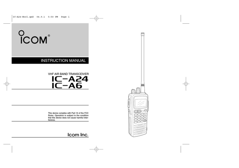
Icom IC-A24 User manual

S-14115HZ-C1-q
July. 2007
VHF AIR BAND TRANSCEVER
iC-a24
iC-a24e
iC-a6
iC-a6e

This service manual describes the latest service information
for the IC-A24/E and IC-A6/A6E VHF AIR BAND
TRANSCEIVER at the time of publication.
NEVER connect the transceiver to an AC outlet or to a DC
power supply that uses more than specified. This will ruin
the transceiver.
DO NOT expose the transceiver to rain, snow or any liquids.
DO NOT reverse the polarities of the power supply when
connecting the transceiver.
DO NOT apply an RF signal of more than 20 dBm (100 mW) to
the antenna connector. This could damage the transceiver’s
front-end.
To upgrade quality, any electrical or mechanical parts and
internal circuits are subject to change without notice or
obligation.
MODEL VERSION WX RX VOR
IC-A24
[USA]
Ye s
Ye s
[USA-1]
[USA-2]
[GEN]
[CHN] Yes
IC-A24E [EUR] No
[UK] No
IC-A6
[USA]
Ye s
No
[USA-1]
[USA-2]
[GEN]
[AUS] No
IC-A6E [EUR] No
[UK]
Be sure to include the following four points when ordering
replacement parts:
1. 10-digit Icom parts numbers
2. Component name
3. Equipment model name and unit name
4. Quantity required
<ORDER EXAMPLE>
1110003491 S.IC TA31136FNG IC-A24 RF UNIT 5 pieces
8820001210 Screw 2438 screw IC-A24 Top cover 10 pieces
Addresses are provided on the inside back cover for your
convenience.
Icom, Icom Inc. and logo are registered trademarks of Icom Incorporated (Japan) in the United States, the United
Kingdom, Germany, France, Spain, Russia and/or other countries.
ORDERING PARTS
1. Make sure the problem is internal before disassembling
the transceiver.
2. DO NOT open the transceiver until the transceiver is
disconnected from its power source.
3. DO NOT force any of the variable components. Turn
them slowly and smoothly.
4. DO NOT short any circuits or electronic parts. An
insulated tuning tool MUST be used for all adjustments.
5. DO NOT keep power ON for a long time when the
transceiver is defective.
6. DO NOT transmit power into a Standard Signal
Generator or a Sweep Generator.
7. ALWAYS connect a 50 dB to 60 dB attenuator between
the transceiver and a Deviation Meter or Spectrum
Analyzer when using such test equipment.
8. READ the instructions of test equipment throughly
before connecting a test equipment to the transceiver.
REPAIR NOTES
INTRODUCTION
CAUTION

TABLE OF CONTENTS
SECTION 1 SPECIFICATIONS
SECTION 2 INSIDE VIEWS
SECTION 4 CIRCUIT DESCRIPTION
4 - 1 RECEIVER CIRCUITS . . . . . . . . . . . . . . . . . . . . . . . . . . . . . . . . . . . . . . . . . . . . . . . . . . . . . . . . . . . . . . .4 - 1
4 - 2 TRANSMITTER CIRCUITS . . . . . . . . . . . . . . . . . . . . . . . . . . . . . . . . . . . . . . . . . . . . . . . . . . . . . . . . . . . .4 - 2
4 - 3 PLL CIRCUIT. . . . . . . . . . . . . . . . . . . . . . . . . . . . . . . . . . . . . . . . . . . . . . . . . . . . . . . . . . . . . . . . . . . . . . .4 - 3
4 - 4 POWER SUPPLY CIRCUITS. . . . . . . . . . . . . . . . . . . . . . . . . . . . . . . . . . . . . . . . . . . . . . . . . . . . . . . . . . .4 - 4
4 - 5 CPU PORT ALLOCATIONS. . . . . . . . . . . . . . . . . . . . . . . . . . . . . . . . . . . . . . . . . . . . . . . . . . . . . . . . . . . .4 - 5
SECTION 5 ADJUSTMENT PROCEDURES
5 - 1 PREPARIOTION . . . . . . . . . . . . . . . . . . . . . . . . . . . . . . . . . . . . . . . . . . . . . . . . . . . . . . . . . . . . . . . . . . . .5 - 1
5 - 2 SOFT WEAR ADJUSTMENT . . . . . . . . . . . . . . . . . . . . . . . . . . . . . . . . . . . . . . . . . . . . . . . . . . . . . . . . . .5 - 3
SECTION 6 PARTS LIST
SECTION 7 MECHANICAL PARTS AND DISASSEMBLY
SECTION 8 SEMI-CONDUCTOR INFORMATION
SECTION 9 BOARD LAYOUTS
9 - 1 LOGIC UNIT . . . . . . . . . . . . . . . . . . . . . . . . . . . . . . . . . . . . . . . . . . . . . . . . . . . . . . . . . . . . . . . . . . . . . . .9 - 1
9 - 2 RF UNIT. . . . . . . . . . . . . . . . . . . . . . . . . . . . . . . . . . . . . . . . . . . . . . . . . . . . . . . . . . . . . . . . . . . . . . . . . . .9 - 3
SECTION 10 BLOCK DIAGRAM
SECTION 11 VOLTAGE DIAGRAMS
11 - 1 LOGIC UNIT . . . . . . . . . . . . . . . . . . . . . . . . . . . . . . . . . . . . . . . . . . . . . . . . . . . . . . . . . . . . . . . . . . . . . .11 - 1
11 - 2 RF UNIT. . . . . . . . . . . . . . . . . . . . . . . . . . . . . . . . . . . . . . . . . . . . . . . . . . . . . . . . . . . . . . . . . . . . . . . . . .11 - 2

1 - 1
SECTION 1 SPECIFICATIONS
▄GENERAL
• Frequency coverage : TX 118.000–136.975 MHz
RX 108.000–136.975 MHz [IC-A24/E]
118.000–136.975 MHz [IC-A6/E]
WX 161.650–163.275 MHz [USA] only
• Type of emission : 6K00A3E, 16K0G3E (Weather channel; [USA] only)
• Channel spacing : 25 kHz
• Number of memory channels : 20 channels ×10 banks
• Power supply requirement :
Specified ICOM's battery packs (BP-208N, BP-209N, BP-210N, BP-211N)
• External power supply requirement : 11.0 V DC
• Current drain (at 7.2 V DC) : Transmit 1.5 A typical
Receive 300 mA typical (AF max.)
70 mA typical (Stand-by)
• Operating temperature range : –10°C to +60°C; +14°F to +140°F [GEN], [USA], [CHN]
–20°C to +55°C [EUR]
–10°C to +50°C [AUS]
• Frequency stability : ±5 ppm
• Antenna connector : BNC type (50 Ωnominal)
• Dimensions (projections not included) : 129.3(W) × 54(H) ×35.5(D) mm; 53⁄32(W) × 21⁄8(H) ×113⁄32(D) in
• Weight (antenna, battery pack not included) : 180 g; 611⁄32 oz (Approx.)
▄TRANSMITTER
• RF output power (at 7.2 V DC) : 5.0 W (PEP) typical, 1.5 W (CW) typical [GEN], [USA], [CHN]
3.6 W (PEP) typical, 1.0 W (CW) typical [EUR], [AUS]
• Modulation system : Low level modulation
• Modulation limiting : 70–100% [GEN], [USA], [CHN]
• Modulation depth : 85% [EUR]
85% to 95% [AUS]
• Audio harmonic distortion : Less than 10% (at 60% modulation) [GEN], [USA], [CHN]
Less than 10% (at 85%±3 dB modulation) [EUR]
• Hum and noise ratio : More than 35 dB [GEN], [USA], [CHN]
• Spurious emissions : More than 46 dB [GEN], [USA], [CHN]
(except operating frequency ±62.5 kHz range)
• Harmonic spurious emissions : Less than –36 dBm [EUR]
(except operating frequency ±1 MHz range) Less than –26 dBm [AUS]
• Microphone connector impedance : More than 100 kΩ (3-conductor 2.5(d) mm (1⁄10"))
▄RECEIVER
• Receive system : Double conversion superheterodyne
• Intermediate frequencies : 1st 30.05 MHz
2nd 450 kHz
• Sensitivity :
VOR (AM 6 dB S/N) 0.71 µV typical [IC-A24/E]
COM (AM 6 dB S/N) 0.5 µV typical [GEN], [USA], [CHN]
COM (AM 12 dB SINAD with CCITT filter) 0.71 µV typical [EUR], [AUS]
WX (FM 12 dB SINAD) 0.22 µV typical [USA]
• Threshold squelch sensitivity : Less than 1 µV (AM)
Less than 0.45 µV (FM for WX channel) [USA]
• Selectivity : More than 7.5 kHz/6 dB, Less than 25 kHz/60 dB
except [AUS]
More than 60dB [AUS]
• Spurious response rejection ratio : More than 60 dB (AM), More than 30 dB (FM)
[GEN], [USA], [CHN]
More than 70 dB (AM) [EUR]
More than 60 dB (AM) [AUS]
• Audio output power (at 7.2 V DC) : 500 mW typical
(at 10% distortion with an 8 Ωload, 30% modulation)
• Hum and noise : More than 40 dB at 30% modulation [GEN], [USA], [CHN]
More than 40 dB at 90% modulation [EUR]
More than 30 dB [AUS]
• External speaker connecter : 3-conductor 3.5(d) mm (1⁄8")/ 8 Ω
Specifications are measured in accordance with FCC Part87 ([USA]], [GEN], [CHN]), EN300 676 ([EUR], [UK]) or AS/NZS 4583:1999 ([AUS])
All stated specifications are subject to change without notice or obligation.

2 - 1
SECTION 2 INSIDE VIEWS
VOR circuit
(IC-A24 only)
CPU
(IC1: μPD78F0338GC-9EB)
RESET IC
(IC2: BD5245G)
EEPROM
(IC7: S-24CS64A01-T8T1-G)
CPU5V regulator
(IC3: XC6202P502PR)
LED DRIVE
Q1: 2SB1132
Q2: 2SC4211
+5V regulator
(IC16: S-812C50BM-C5E-G)
Clock oscillator
(X1: CR-747 9.8304 MHz)
LED DRIVE
(Q8, Q9: UNR9213J)
VOR circuit
(IC-A24/A24E only)
CPU
(IC1: μPD78F0338GC-9EB)
RESET IC
(IC2: BD5245G)
EEPROM
(IC7: S-24CS64A01-T8T1-G)
CPU5V regulator
(IC3: XC6202P502PR)
LED drivers
Q1: 2SB1132
Q2: 2SC4211
+5V regulator
(IC16: S-812C50BMC-C5E-G)
Clock oscillator
(X1: CR-747 9.8304 MHz)
LED drivers
(Q8, Q9: UNR9213J×2)
TX final amplifier
(Q2: RD12MVS1)
Antenna switching
D8, D9:
HVU131TRF
ALC amplifier
(D4: 1SV246)
VCO circuit
Electric volume
(IC17: M62363FP-650C) AF/FM switch
(IC2: TC4W53FU)
PLL IC
(IC3: TB31207AFN)
R5S regulator
(Q20: UNR9115J)
RX 1st mixer
(Q12: 3SK299)
RF amplifier
(Q11: 3SK293)
T5V regulater
Q7: 2SB1132
Q8: 2SC4211
D7: MA111
2nd IF IC
(IC1: TA31136FN)
VOR switching
Q19: UNR9215J
IC-A24 only
AGC amplifier
(Q14: 2SD1819A)
DC power switching
(Q24: HAT1024R)
ALC amplifier
IC15: AN6123MS
IC19: NJM2107F
Power amplifier
(Q2: RD12MVS1)
Antenna switches
D1, D8:
HVU131TRF×2
ALC attenator
(D4: 1SV246)
VCO circuit
Electric volume
(IC17: M62363FP-650C) AM/FM switch
(IC2: TC4W53FU)
PLL IC
(IC3: TB31207AFN)
R5S regulator
(Q20: UNR9115J)
RX 1st mixer
(Q12: 3SK299)
RF amplifier
(Q11: 3SK293)
T5V regulater circuit
Q7: 2SB1132
Q8: 2SC4211
D7: MA111
FM IF IC
(IC1: TA31136FN)
VOR switch
Q19: UNR9215J
IC-A24/A24E only
AGC amplifier
(Q14: 2SD1819A)
DC power switch
(Q24: HAT1024R)
ALC amplifiers
IC15: AN6123MS
IC19: NJM2107F
TX final amplifier
(Q2: RD12MVS1)
Drive amplifier
(Q3: RD01MUS1)
• LOGIC UNIT
• RF UNIT (TOP VIEW)
• LOGIC UNIT
• RF UNIT (BOTTOM VIEW)

3 - 1
SECTION 3 DISASSEMBLY INSTRUCTION
E
E
LOGIC/RFunit
Front panel
A
D
B
F
J4
J4
C
J
I
J
LOGICunit
RFunit
J
H
G
RFunit
L
M
L
K
Becareful not tobreak andlost thesealingwasher.
• REMOVING THE CHASSIS PANEL
1Remove the Jack cap A.
2Remove [VOL] knob Band [DIAL] knob C.
3Unscrew the ANT nut D.
4Unscrew 3 screws E.
5Disconnect the connector Ffrom J4 and remove the
LOGIC/RF unit from the Front panel.
• REMOVING THE LOGIC UNIT
1Remove the main seal G.
• REMOVING THE RF UNIT
1Unsolder 2 points K.
2Unscrew 6 screws L.
3Unscrew 2 screws Mand remove the RF unit from the
chassis unit.
2Unsolder 1 point H.
3Unscrew 2 nuts I.
4Unscrew 3 screws Jand remove the LOGIC unit from
the RF unit.
Continue to right above.

4 - 1
SECTION 4 CIRCUIT DESCRIPTION
ANT
ANT
LPF BPF BPF
BPF
BPF
D8, D9 D13
SW
RF
AMP
AMP
Q11 D14–D16 Q12
1st Mixer
Fl1
XTAL
Q13
16
5
9
7
6
1
3
1st lF
lC1
2nd Mixer
AMP
2nd lF
AMP
2nd lFAM
FM
ANL
IC1
AM signal
FM signal
AM/FM
AF sigunal
to the AF circuit
IC2 FI2
Q15
Q16, Q17
Q18D18
DET
DET
Switch
• RF AND IF CIRCUIT
4-1 RECEIVER CIRCUITS
4-1-1 ANTENNA SWITCHING CIRCUIT (RF UNIT)
The antenna switching circuit functions as a low-pass filter
while receiving. However, its impedance becomes very high
while D8 and D9 are turned ON. Thus transmit signals are
blocked from entering the receiver circuits. The antenna
switching circuit employs a λ/4type diode switching system.
Received signals are passed through the low-pass filter
(L1–L3, L45, C3–C7, C210, C211). The filtered signals are
applied to the λ/4type antenna switching circuit (D8, D9).
The passed signals are then applied to the RF amplifier cir-
cuit.
4-1-2 RF CIRCUIT (RF UNIT)
The RF circuit amplifies signals within the range of frequen-
cy coverage and filters out-of-band signals.
The signals from the antenna switching circuit are
amplified at the RF amplifier (Q11) after passing
through the tunable bandpass filter (D13, L18, L70,
C58, C60). The amplified signals are applied to the
1st mixer circuit (Q12) after out-of-band signals are
suppressed at the another tunable bandpass filter
(D14–D16, D44, L22, L23, C70–C79).
Varactor diodes are employed at the bandpass filters
(D13–D16, D44) that track the filters and are controlled by
the CPU (LOGIC unit; IC1) via the expander IC (IC17) using
bandpass filter control voltages (T1–T4). These diodes tune
the center frequency of an RF passband for wide bandwidth
receiving and good image response rejection.
4-1-3 1ST MIXER AND 1ST IF CIRCUITS (RF UNIT)
The 1st mixer circuit converts the received signal into a fixed
frequency of the 1st IF signal with a PLL output frequency.
By changing the PLL frequency, only the desired frequency
will pass through a crystal filter at the next stage of the 1st
mixer.
The signals from the RF circuit are mixed at the 1st mixer
(Q12) with a 1st LO signal (AM; 77.95–106.925 MHz,
FM; 131.6–133.225 MHz) coming from the VCO circuit to
produce a 30.05 MHz 1st IF signal.
The 1st IF signal is applied to a crystal filter (FI1) to sup-
press out-of-band signals. The filtered 1st IF signal is
applied to the 1st IF amplifier (Q13), then applied to the 2nd
mixer circuit (IC1, pin 16).
4-1-4 2ND IF AND DEMODULATOR CIRCUITS (RF
UNIT)
The 2nd mixer circuit converts the 1st IF signal into a 2nd IF
signal. A double conversion superheterodyne system (which
converts receive signals twice) improves the image rejection
ratio and obtains stable receiver gain.
The IF IC contains the 2nd local oscillator, 2nd mixer, limiter
amplifier, quadrature detector and s-meter detector circuit,
etc.
The 1st IF signal from the 1st IF amplifier (Q13) is applied to
the 2nd mixer section of the IF IC (IC1, pin 16), and is mixed
with a 29.6 MHz 2nd LO signal generated at the PLL cir-
cuit using the reference frequency (29.6 MHz) to produce a
450 kHz 2nd IF signal.
The 2nd IF signal from the 2nd mixer (IC1, pin 3) passes
through a ceramic filter (FI2) to remove unwanted hetero-
dyned frequencies. The filtered signal is amplified at the IF
amplifier (Q15), and is then applied to the AM detector cir-
cuit or FM detector circuit respectively.
(1) AM DETECTOR CIRCUIT
The amplified signal is amplified again at the 2nd IF ampli-
fiers (Q16, Q17) and applied to the AM detector (Q18) to
demodulate the 2nd IF signal into AF signals.
The demodulated AF signals are applied to the AM/FM
switch (IC2, pin 6) via the ANL circuit (D18).
4 - 2
R5
R5
AM AF signal
to the AM/FM
switch (IC2, pin 6)
FM AF signal to the
AM/FM switch (IC2, pin7)
IC2 TA31136F
1st IF (30.05 MHz) from
the IF amplifier (Q13)
Q18
C111 R92
R95 C108
Q17
R97 R96 R94 C112 C109
D40
Q16
AM
FM
Q15
R89
R86
R91
R87
C101
C104
C103
D41
FI2
2nd IF filter
450 kHz
3
Mixer
2
(29.6 MHz) 14
PLL IC
IC3
5
X2
29.6 MHz
16
IF amp.
detector
FM
11910
C91 C201
X1
R5
R71
R72
R73 R274
C95 C93 C92
AF signal to the AM/FM switch (IC2)
AGC
AMP
AGC
AMP
AMP
2nd lF
AMP
2nd lF
AMP
2nd lF
AM
DET
Q18 Q17 Q16 Q15
2nd IF signal from
the 2nd mixer (IC1)
Q14
Q10
to the 1st IF amplifier (Q13)
to the RF amplifier (Q11)
• 2ND IF AND DEMODULATOR CIRCUIT
• AGC CIRCUIT
(2) FM DETECTOR CIRCUIT
The amplified signal is applied to the limiter amplifier section
of the IF IC (IC1, pin 5) and is then applied to the quadra-
ture detector (IC1, pins 10, 11) to demodulate the 2nd IF
signal into AF signals.
The demodulated AF signals are output from pin 9 of the
IC1 and are applied to the AM/FM switch (IC2, pin 7).
4-1-5 AF CIRCUIT (RF UNIT)
The AF amplifier circuit amplifies the demodulated AF sig-
nals to drive a speaker.
AF signals from the AM detector (Q18; While in AM mode)
or IF IC (IC1, pin 9; While in FM mode) are applied to the
AM/FM switch (IC2, pin 6 or 7). The output signals from
pin 1 are applied to the AF amplifier (IC18, pins 1, 2), and
then pass through the low-pass filter (IC18, pins 5, 7, 8, 10).
The filtered signals are amplified at the OP-amplifier (IC18,
pins 13, 14), and are then applied to the AF power amplifier
(IC6, pin 4) to obtain the specified audio level after being
passed through the electric volume (IC17, pins 21, 22). The
amplified AF signals are applied to the internal speaker (SP1)
via the [SP] jack (J5) when no plug is connected to the jack.
4-1-6 SQUELCH CIRCUIT (RF AND LOGIC UNITS)
A squelch circuit cuts out AF signals when no RF signals
are received. By detecting noise components in the AF sig-
nals, the squelch switches the AF mute switch.
The AGC signal from the AGC amplifier (Q10) is amplified
again at the RSSI amplifier (IC13) and is then applied to the
CPU (LOGIC unit; IC1,pin 29) as the “RSSI” signal.
The CPU analyzes the noise condition and outputs the con-
trol signal to the expander IC (IC5). The expander IC (IC5,
pin 4) outputs the squelch control signal as the “AFC” sig-
nal. The signal is applied to the AF out control circuit (Q36,
Q35) to control the power amplifier (IC6) and cut the AF
signal line.
4-1-7 AGC CIRCUIT (RF UNIT)
The AGC (Automatic Gain Control) circuit reduce signal fad-
ing and keeps the audio output level constant.
AF signals from the AM detector circuit (Q18) are applied
to the AGC amplifier circuits (Q14; for 1st/2nd IF amplifiers,
Q10; for RF amplifier, Q9; for RF attenuator). The signal
from the AGC amplifiers is applied to the 1st/2nd IF ampli-
fiers (Q13, Q15, Q16) and RF amplifier (Q11) to reduce the
amplifier gain and RF attenuator (D29) to attenuate the RF
signals when strong signals are received.
When strong RF signals disappear, then the AGC signal is
released to keep the constant audio output level.

4 - 3
ALC5V
"VORDET" signal from
the AM detector (Q18)
IC12
IC11IC13
IC14
35
5
1
1
14
82
2
10 kHz
30 kHz
BPF
BPF
BIAS
Buff.
Limit.
FM
DET
77
7
3
Phase
shift
LPF
3
6
Comp.
Comp.
"VORS" signal to the
CPU (IC1, pin 2)
"VORC" signal to the
CPU (IC1, pin 3)
"VORD" signal to the
CPU (IC1, pin 28)
Amp.
To IC2, pin 6
R102
D18 R99
R100
Q21
C115 R101
AM AF signal
from Q18
"ANLC" signal
from IC5, pin 7
• ANL CIRCUIT
• VOR NAVIGATION CIRCUIT
4-1-8 ANL CIRCUIT (RF UNIT)
The ANL (Automatic Noise Limiter) circuit (Q21, D18)
reduces noise components.
The AM detector output signal from the Q18 is applied to
the cathode of D18 passing through R99 where it is divided
by R99 and R100. The signal is also applied to the anode of
D18, passing through R101 and R102.
When the ANL function is activated (Q21 is ON), C115 is
grounded. The detector output, including noise components,
are applied to the cathode of D18 only. If noise components
are received, the cathode voltage of D18 becomes higher
than the anode voltage and D18 turns OFF. Thus, while
noise components are received, the detected signal is not
applied to IC2.
4-1-9 VOR NAVIGATION CIRCUIT (LOGIC UNIT)
(IC-A24/E ONLY)
From the AF signal, the VOR circuit detects a variable signal
(VORC) and reference signal (VORS) from a VOR station.
The VOR circuit sends these signals to the CPU (IC1).
When the transceiver is set in the navigation band (108.000
–117.975 MHz), the VORON port of the CPU (IC1, pin 118)
becomes “HIGH” turning the VOR circuit ON via Q15. Q15
controls a 5 V power source for the VOR circuit.
The signal from the AM detector (VORDET) is buffer ampli-
fied at the OP-AMP IC (IC12).
The “VORDET” signal includes 30 Hz variable phase com-
ponents and 9960 Hz reference phase components.
The 30 Hz component passes through the 30 Hz bandpass
filter (IC12, R83–R88, C112, C113), and is converted to
a square-wave signal at the VORS comparator (IC14).
The square-wave signal is then applied to the
CPU (IC1,
pin 2) as variable signal (VORS).
The 9960 Hz component passes through the 10 kHz
bandpass filter (IC12, R79–R82, C108, C109). These com-
ponents are FM modulated with 480 Hz deviation and 30 Hz
modulation.
Signals are then amplified at a limiter amplifier (IC11), and
detected at an FM detector (IC11) to obtain a 30 Hz refer-
ence signal.
The 30 Hz signal is compensated on phase at IC12. This
signal is passed through the 30 Hz low-pass filter (IC12)
and is converted to a square-wave signal at the VORC com-
parator (IC14). This signal is applied to the CPU (IC1, pin 3)
as a reference signal (VORC).
A portion of output from the buffer amplifier (IC12) is applied
to the amplifier (Q13). When VOR level is low or receiving
the signal except VOR signal, output from IC12 is reduced.
Output signal from Q13 is applied to the CPU (IC1, pin 28)
as a “OFF FLAG” signal (VORD).

4 - 4
4-2 TRANSMITTER CIRCUITS
4-2-1 MICROPHONE AMPLIFIER CIRCUIT (RF UNIT)
The microphone amplifier circuit amplifies audio signals with
+6 dB/octave pre-emphasis characteristics from the micro-
phone to a level needed for the modulation circuit.
AF signal from the internal/external microphone are applied
to the microphone amplifier (IC15, IC19) via the microphone
mute switch (Q51) and the microphone volume controller
(IC17; pins 15, 16). The amplified signals are applied to the
AF controller (IC17, pins 13, 14, and are then applied to
buffer amplifier (IC18, pins 1, 2). Amplified signals passes
through the low-pass filters (IC18, pins 4, 5, 8, 10) and are
then applied to the modulation circuit (D5, D51).
4-2-2 MODULATION CIRCUIT (RF UNIT)
The modulation circuit modulates the TX LO signal from the
VCO (RF signal) using the microphone audio signal.
While in transmission, the LO signal from the VCO circuit
(Q58, D38, D48) is amplified at the buffer amplifiers (Q28,
Q60) and passed through the LO switch (D6). This signal is
then applied to the AM modulator (D5, D51).
The buffer amplifier (Q6) amplifies the LO signal with a gain
controlled by an AF signal to make low level modulation.
TX signal from the
buffer amplifier (Q6)
ALC
AT T D4
R25
R26
C38
Q5 C37 R24
R23
C38
From the D/A converter
(IC16, pin 4)
ALC
amplifier
Pre-drive
Q4 Q3 Q2
T5
T5
Q1
R11
VCC VCC
amplifier
Driver
amplifier
Power
PWR
DET LPF
To the antenna
D2, D3
"RFDETV" signal to the CPU
(LOGIC unit; IC1, pin 30)
4-2-3 DRIVE/POWER AMPLIFIER CIRCUITS
(RF UNIT)
The drive amplifier circuit amplifies the transmit signal to
a level needed for the power amplifier circuit. The power
amplifier circuit amplifies this to obtain a specified transmit
output power.
The modulated RF signal from the buffer amplifier (Q6) is
applied to the pre-drive amplifier (Q4) after being passed
through the ALC attenuator (D4). The signal is amplified at
the YGR (Q3) and power amplifier (Q2) to obtain 5 W (PEP)
(3.6 W (PEP) for [EUR]) of RF power. The amplified signal
passes through the low-pass filter (L6, L46, C22, C212,
C297, C299). The filtered signal is applied to the antenna
connector (CHASSIS unit; J1) via the power detector (D2,
D3, L5), antenna switch (D1) and low-pass filter (L1–L3,
L45, C3–C7, C210, C211).
4-2-4 ALC CIRCUIT (RF UNIT)
The ALC (Automatic Level Control) circuit controls the input
level of the pre-drive amplifier to obtain stable output power.
The power detector circuit (D2, D3) detects transmit out-
put power level. The detected voltage are combined and is
then amplified at the ALC amplifier (Q5) after being passed
through the ALC controller (Q1). The amplified signal is
applied to the ALC attenuator (D4) to obtain stable output
power.
• MODULATION CIRCUIT

4 - 6
Shift register
Prescaler
Phase
detector
Loop
filter
Programable
counter
Programable
divider
X2
29.6 MHz
“2nd LO” signal
to the FM IF IC 14
Q59, D39, D45–D47
RX VCO
TX VCO
Buffer
Buffer
Buffer
Q28
Q29
Q60
3
8
4
5
PLST
IC3 (TB31207)
SO
SCK
to transmitter circuit
to 1st mixer circuit
D17
D6
9
Q58, D38, D48
4-4 POWER SUPPLY CIRCUITS
VOLTAGE LINES (MAIN UNIT)
LINE DESCRIPTION
HV The voltage from the connected DC power
supply.
VCC
The same voltage as the HV line or battery
voltage through the power switch (Q24, D19,
D22).
CPU 5
Common 5 V converted from the HV line at
the CPU5V regulator circuit (LOGIC unit;
IC3). The output voltage is applied to the
CPU (LOGIC unit; IC1), reset IC (LOGIC
unit; IC2) and EEPROM
(LOGIC unit; IC7),
etc.
+5V
Common 5 V converted from the VCC line
by the +5 V regulator circuit (LOGIC unit;
IC16, Q4, Q6, Q7, D10). The output voltage
is applied to the PLL IC (RF unit; IC3) and
D/A convertor IC (RF unit; IC17), etc.
T5V
Transmit 5 V controlled by the T5V regula-
tor circuit (RF unit; Q7, Q8, D8) using TXC
signal from the CPU (LOGIC unit; IC1). The
output voltage is applied to the buffer ampli-
fier (RF unit; Q6) and pre-driver (RF unit;
Q4), etc.
R5S
Receive 5 V controlled by the R5S regulator
circuit (Q20) using R5C signal from the CPU
(LOGIC unit; IC1). The output voltage is ap-
plied to the RF amplifier (RF unit; Q12) and
1st IF amplifier (RF unit; Q13), etc.
4-3 PLL CIRCUITS (RF UNIT)
A PLL circuit provides stable oscillation of the transmit
frequency and receive 1st LO frequency. The PLL output
compares the phase of the divided VCO frequency to the
reference frequency. The PLL output frequency is controlled
by the divided ratio (N-data) of a programmable divider.
The PLL circuit contains the TX VCO circuit (Q58, D38,
D48) and RX VCO circuit (Q59, D39, D45–D47). The oscil-
lated signal is amplified at the buffer-amplifiers (Q60, Q29)
and then applied to the PLL IC (IC3, pin 8).
The PLL IC contains a prescaler, programmable counter,
programmable divider and phase detector, etc. The entered
signal is divided at the prescaler and programmable counter
section by the N-data ratio from the CPU. The divided signal
is detected on phase at the phase detector using the refer-
ence frequency.
If the oscillated signal drifts, its phase changes from that of
the reference frequency, causing a lock voltage change to
compensate for the drift in the oscillated frequency.
A portion of the VCO signal is amplified at the buffer-ampli-
fier (Q28) and is then applied to the receive 1st mixer (Q12)
or transmit buffer-amplifier circuit (Q6) via the T/R switches
(D6, D17).
• PLL CIRCUIT

1 - 2
4-5 PORT ALLOCATIONS
4-5-1 CPU (LOGIC unit; IC1)
Pin
number
Port
name Description
1 PCON Outputs control signal for the 5 V
regulator (IC16, Q4, Q6, Q7, D10).
2 VORS Input port for the 30 Hz phase signal.
3 VORC Input port for the VOR 30 Hz standard
signal.
4 BPCPI Outputs the bias control signal for a
type of battery.
5 LIGHT Input port for [LIGHT] switch.
6 CLIN Input port for the cloning signal.
7 CLOUT Outputs the cloning signal.
10 EDATA I/O port for data signal from/to the
EEPROM (LOGIC unit; IC7)
11 ECK Outputs clock signal to the EEPROM
IC (LOGIC unit; IC7).
12 POWER Input port for [POWER] switch.
13 PTT
Input port for [PTT] switch.
High: While [PTT] switch is
pushed.
14 UNLK Input port for the PLL unlock signal.
Low: PLL is unlocked.
17 DCC Input port for the external DC connec-
tion detection.
25 RESET Input port for the CPU reset signal.
28 VORD Input port for the VOR signal detec-
tion.
29 RSSI Input port for the receive signal level.
30 RFDETV Input port for the power detection of
power amplifier (RF unit; Q2).
31 THRMC Input port for the transceiver's internal
temperature.
32 SBATT Input port for the battery type detec-
tion.
34 VIN Input port for the battery voltage de-
tection.
38 BEEP Outputs BEEP audio signals.
109 PSTB Outputs strobe signal to the PLL IC
(RF unit; IC3).
110 PDATA Outputs data signals to the PLL IC (RF
unit; IC3).
111 PCK Outputs clock signal to the PLL IC (RF
unit; IC3).
112 TXC Outputs control signal to the T5 regu-
lator circuit (Q7, Q8, D8).
115 JACKDET
Input port for external SP jack con-
nection detection.
High: While external SP jack is
connected.
119, 120 DICK,
DIUD Input ports for [DIAL].
4-5-2 EXPANDER (RF unit; IC5)
Pin
number
Port
name Description
4 AFC
Outputs control signal to the AF out
controller (Q35, Q36) for AF amplifier
(IC6).
5 ALCC Outputs control signal to the ALC con-
troller (Q52).
6 R5C Outputs control signal to the R5V
regulator (Q20).
7 ANLC Outputs control signal to the ANL
switch (Q21).
11 MMUT Outputs control signal for MIC mute
switch (Q51).
12 DET-
MUT
Outputs detector mute signal to the
AM/FM switch (IC2, pin 2).
13 SHIFT Outputs shift control signal to the
VCO switch (Q57).
14 WXC Outputs AM/FM (WX ch) select signal
to the AM/FM switch (IC2, pin 5).
4-5-3 EXPANDER (RF unit; IC17)
Pin
number
Port
name Description
2, 3,
10, 11 T1–T4 Outputs the bandpass filter tuning
control signal.
14 MOD70 Outputs modulation control signal to
the buffer-amplifier (IC18).
15 MOD30 Outputs modulation control signal to
the ALC amplifier (IC19).
23 VOL Outputs AF volume control signal to
the AF amplifier (IC6).

5 - 1
SECTION 5 ADJUSTMENT PROCEDURE
5-1 PREPARATION
Most of adjustment must be adjusted in the "ADJUSTMENT MODE." CS-A24 CLONING SOFTWARE (REV. 1.0 or later) and
OPC-478/U/UC CLONING CABLE are required.
■REQUIRED TEST EQUIPMENT
EQUIPMENT GRADE AND RANGE EQUIPMENT GRADE AND RANGE
DC power supply Output voltage
Current capacity
: 7.2 V/11 V
: 5 A or more Audio generator Frequency range
Measuring range
: 300–3000 Hz
: 1–500 mV
RF power meter
(terminated type)
Measuring range
Frequency range
Impedance
SWR
: 0.1–10 W
: 100–200 MHz
: 50 Ω
: Less than 1.2 : 1
Attenuator Power attenuation
Capacity
: 20 or 30 dB
: More than 10 W
Standard signal
generator (SSG)
Frequency range
Output level
: 0.1–300 MHz
: 0.1 µV to 32 mV
(–127 to –17 dBm)
Frequency counter
Frequency range
Frequency accuracy
Sensitivity
: 0.1–300 MHz
: ±1 ppm or better
: 100 mV or better DC ammeter Measuring range : 100–500 mA
Modulation analyzer Frequency range
Measuring range
: 30–300 MHz
: 0–100% Distortion meter Frequency range
Measuring range
: 1 kHz±5%
: 1–100%
DC voltmeter Input impedance : 10 MΩ/V DC or better AC millivoltmeter Measuring range : 10mV to 10 V
External speaker Input impedance
Capacity
: 8 Ω
: More than 1 W
DC Ammeter Mesurring range :100 mA to 1 A
■ENTERING ADJUSTMENT MODE
1. Turn transceiver’s power off. Connect IC-A24/A6 and PC
with the optional OPC-478/U/UC.
2. Right click the CS-24's icon on the desktop and select the
"Properties", then CS-24 propaties window appears.
3. Type "C:\Program File\Icom\CS-A24\CSA24.exe /expert"
on the "Target" box and double click CS-A24's icon, then
CS-A24 window appears.
4. Click [EXPERT] button, then "Expert window" appears.
Select "Enable" the "Adjust Mode" box, and then cloning.
5. Turn power OFF. Disconnect OPC-478/U/UC from the
transceiver.
6. Push and hold [CLR] and [SQL], then turn power ON.
■OPERATING ON THE ADJUSTMENT MODE
Store the adjustment value : [ENT]
Change the adjustment item [UP] : [121.5]
Change the adjustment item [DOWN] : [MR]
Change the adjustment value : [DIAL]
■EXITING THE ADJUSTMENT MODE
When the adjustment is finished, the transceiver must be
cancelled adjustment mode to use normal operation, other-
wise the transceiver does not work properly.
1. Turn transceiver’s power OFF and then power ON again.
2. Select "Disable" the "Adjust Mode" box on cloning soft-
ware, and then cloning the original memory data.
3. Turn power OFF.
Microsoft and Windows are registered trademarks of Micro-
soft Corporation in the U.S.A. and other countries.
■SYSTEM REQUIREMENT
• RS-232C serial port or USB port
• Microsoft®Windows®98/SE/ME/2000/XP
■CLONING SOFTWARE INSTALLATION
1. Quit all applications when Windows is running.
2. Insert the CD into the appropriate CD drive.
3. Double-click the “Setup.exe” contained in the CD drive.
4. The “Welcome to the InstallShield Wizard for CS-A24” will
appear. Click [Next>].
5. The “User Information” will appear, then type your name,
your company name and the product ID number with the
following manner. Then click [Next >].
• ID number: 279201-(6 digit serial number)
• e.g. the serial number on the CD is 000101, enter
“279201-000101” as the ID number.
6. The “Choose Destination Location” will appear. Then click
[Next>] to install the software to the destination folder. (e.g.
C:\Program Files\Icom\CS-A24)
7. After the installation is completed, the “InstallShield Wiz-
ard Complete” will appear. Then click [Finish].
8. Eject the CD.
9. Program group ‘CS-A24’ appears in the ‘Programs’ folder
of the start menu, and ‘CS-A24’ icon appears on the desk
top screen.
CAUTION!: BACK UP the originally programmed memory
data in the transceiver before starting the ad-
justment.

5 - 2
Battery type detector
Modulation
analyzer
Distortion meter
AC millivoltmeter
DC POWER
SUPPLY
11 V/5 A
Speaker (8 Ω)
Audio generator
AC millivoltmeter
to the antenna connector
Attenuator
20 dB or 30 dB
RF power meter
0.1−10 W/50 Ω
Frequency
counter
IC-A24/E
IC-A6/E
[DC 11V]
BATTERY
TERMINAL
Standard signal generator
0.1 µV to 32 mV
(−127 dBm to −17 dBm)
CAUTION!
DO NOT transmit while
an SSG is connected to
the antenna connector.
To [SP]
To [MIC]
DC ammeter
DC POWER
SUPPLY
7.2 V/5 A DC ammeter
+
–
PC
to USB port
to RS-232C port
OPC-478 (RS-232C type)
OPC-478U/UC (USB type)
• PC SCREEN IN tHE ADJUSTMENT MODE
• CONNECTION
Operating frequency
Adjustment item
Adjustment value
• DISPLAY IN THE ADJUSTMENT MODE
When entering adjustment mode,
select “Enable” the “Adjust Mode”
Click the [EXPERT]

5 - 3
5-2 ADJUSTMENT
ADJUSTMENT ADJUSTMENT CONDITION OPERATION
IDLING
CURRENT
(for final amp.)
[ ]
1 • Operating frequency: 127.500 MHz
• Connect a DC ammeter between the battery terminal and
DC power supply (7.2 V).
• Measure the current at "00" point (A).
• Rotate [DIAL] to adjust the current
A+500 mA.
• Push [ENT].
2 • Operating frequency: 118.025 MHz
3 • Operating frequency: 136.975 MHz
4 • Operating frequency: 127.500 MHz
• Connect DC ammeter between the [DC 11V] jack and DC
power supply (11 V).
5 • Operating frequency: 118.025 MHz
6 • Operating frequency: 136.975 MHz
move to
"TX OUTPUT POWER"
Push [121.5] key 6 times. (Until you can find [rF])
TX OUTPUT POWER
[ ]
1 • Operating frequency: 127.500 MHz
• Connect a 7.2 V DC power supply to the battery terminal.
• No audio signal apply to the microphone connector.
• Transmitting
• Preset IDLING CURRENT (for driver
amp.) [ ] to 67.
• Rotate [DIAL] to set output power to
1.5 W [USA], [GEN], [CHN]/1.0 W [EUR],
[UK], [AUS]
• Push [ENT] key.
2 • Operating frequency: 118.025 MHz
• Transmitting
3 • Operating frequency: 136.975 MHz
• Transmitting
move to
"IDLING CURRENT"
(for driver amp.)
Push [MR] key 9 times. (Until you can find [db])
IDLING
CURRENT
(for driver amp.)
(PRESET)
[ ]
1 • Operating frequency: 127.500 MHz
• Connect a DC ammeter between the battery terminal and
DC power supply (7.2 V).
• Measure the current at "00" point (B).
• Rotate [DIAL] to adjust the current
B+150 mA.
• Push [ENT] key.
2 • Operating frequency: 118.025 MHz
3 • Operating frequency: 136.975 MHz
4 • Operating frequency: 127.500 MHz
• Connect a DC ammeter between the [DC 11V] jack and
DC power supply (11 V).
5 • Operating frequency: 118.025 MHz
6 • Operating frequency: 136.975 MHz
move to
"MODULATION"
Push [121.5] key 3 times. (Until you can find [d3])
MODULATION
(PRESET)
[ ]
1 • Operating frequency: 118.000 MHz
• Connect a 7.2 V DC power supply to the battery terminal.
• Connect an audio generator to the [MIC] connector and set as:
1 kHz/20 mVrms
• Set a modulation analyzer as:
HPF : OFF
LPF : 20 kHz
Detector : OFF
• Transmitting
• Rotate [DIAL] to set to "80".
• Push [ENT] key.
2 • Connect an 11 V power supply to the [DC 11V] jack.
• Transmitting
MAX.
MODULATION
(PRESET)
[ ]
1 • Operating frequency: 127.500 MHz
• Connect a 7.2 V power supply to the battery terminal.
•
Connect an audio generator to the [MIC] connector and set as:
1 kHz/20 mVrms
• Set a modulation analyzer as:
HPF : OFF
LPF : 20 kHz
Detector : (P–P)/2
• Transmitting
• Rotate [DIAL] to set to 30% modulation.
2 • Operating frequency: 118.025 MHz
• Transmitting
3 • Operating frequency: 136.975 MHz
• Transmitting
Preset to 67 before
adjusting TX output
power.

5 - 4
ADJUSTMENT ADJUSTMENT CONDITION OPERATION
MAX.
MODULATION
(PRESET)
[ ]
4 • Operating frequency: 127.500 MHz
• Connect an 11 V power supply to the [DC 11V] jack.
• Transmitting
• Rotate [DIAL] to set to 30% modulation.
5 • Operating frequency: 118.025 MHz
• Transmitting
6 • Operating frequency: 136.975 MHz
• Transmitting
move to
"IDLING CURRENT"
(for driver amp.)
Push [MR] key 17 times. (Until you can find [db])
IDLING
CURRENT
(for driver amp.)
[ ]
1 • Operating frequency: 127.500 MHz
• Connect a 7.2 V DC power supply to the battery terminal.
• Connect an audio generator to the [MIC] connector and set
as:
1 kHz/20 mVrms
• Set a modulation analyzer as:
HPF : OFF
LPF : 20 kHz
Detector : (P–P)/2
• Transmitting
• Rotate [DIAL] to adjust minimum distor-
tion.
• Push [ENT] key.
2 • Operating frequency: 118.025 MHz
• Transmitting
3 • Operating frequency: 136.975 MHz
• Transmitting
4 • Operating frequency: 127.500 MHz
• Connect an 11 V DC power supply to the [DC 11V] jack.
• Transmitting
5 • Operating frequency: 118.025 MHz
• Transmitting
6 • Operating frequency: 136.975 MHz
• Transmitting
move to
"MAX MODULATION"
(for driver amp.)
Push [MR] key 5 times. (Until you can find [d7])
MAX.
MODULATION
[ ]
1 • Operating frequency: 127.500 MHz
• Connect a 7.2 V DC power supply to the battery terminal.
• Connect an audio generator to the [MIC] connector and set
as:
1 kHz/200 mVrms
• Set a modulation analyzer as:
HPF : OFF
LPF : 20 kHz
Detector : (P–P)/2
• Transmitting
• Rotate [DIAL] to set to 30% modulation
• Push [ENT] key.
2 • Operating frequency: 118.025 MHz
• Transmitting
3 • Operating frequency: 136.975 MHz
• Transmitting
4 • Operating frequency: 127.500 MHz
• Connect an 11 V DC power supply to the [DC 11V] jack.
• Transmitting
5 • Operating frequency: 118.025 MHz
• Transmitting
6 • Operating frequency: 136.975 MHz
• Transmitting
move to
"SENSITIVITY"
Push [121.5] key once. (Skip [rS], and you can find [t1])
5-2 ADJUSTMENT (continued)

5 - 5
SOFTWARE ADJUSTMENT (continued)
ADJUSTMENT ADJUSTMENT CONDITION OPERATION
SENSITIVITY
[ ]
1 • Operating frequency: 108.025 MHz
• Connect an SSG to the antenna connector and set as:
Level : –97 dBm* (3.2 µV)
(No modulation)
• Receiving
• Push [ENT] key.
[ ] 2 • Operating frequency: 127.500 MHz
• Receiving
• Push [ENT] key.
[ ] 3 • Operating frequency: 136.975 MHz
• Receiving
• Push [ENT] key.
[ ] 4 • Operating frequency: 161.650 MHz
• Receiving
• Push [ENT] key.
[ ] 5 • Operating frequency: 163.275 MHz
• Receiving
• Push [ENT] key.
SQUELCH
[ ]
1 • Operating frequency: 108.025 MHz (IC-A24)
118.025 MHz (IC-A6)
• Connect an SSG to the antenna connector and set as:
Level : –111 dBm* (0.63 µV) for IC-A24
–114 dBm* (0.45 µV) for IC-A6
(No modulation)
• Receiving
• Push [ENT] key.
[ ] 2 • Connect an SSG to the antenna connector and set as:
Level : –114 dBm* (0.45 µV) for IC-A24
–117 dBm* (0.32 µV) for IC-A6
(No modulation)
• Receiving
• Push [ENT] key.
[ ] 3 • Connect an SSG to the antenna connector and set as:
Level : –82 dBm* (18 µV)
(No modulation)
• Receiving
• Push [ENT] key.
[ ] 4 • Connect an SSG to the antenna connector and set as:
Level : –85 dBm* (13 µV)
(No modulation)
• Receiving
• Push [ENT] key.
[ ] 5 • Operating frequency: 162.550 MHz
• Connect an SSG to the antenna connector and set as:
Level : –117 dBm* (0.32 µV)
(No modulation)
• Receiving
• Push [ENT] key.
[ ] 6 • Connect an SSG to the antenna connector and set as:
Level : –120 dBm* (0.22 µV)
(No modulation)
• Receiving
• Push [ENT] key.
[ ] 7 • Connect an SSG to the antenna connector and set as:
Level : –82 dBm* (18 µV)
(No modulation)
• Receiving
• Push [ENT] key.
[ ] 8 • Connect an SSG to the antenna connector and set as:
Level : –85 dBm* (13 µV)
(No modulation)
• Receiving
• Push [ENT] key.
*This output level of a standard signal generator (SSG) is indicated as SSG's open circuit.

5 - 6
SOFTWARE ADJUSTMENT (continued)
ADJUSTMENT ADJUSTMENT CONDITION OPERATION
VOR OFF
(IC-A24 only)
[ ]
1 • Operating frequency: 108.000 MHz
• Connect a VOR tester to the antenna connector and set
as:
Level : –90 dBm* (7.1 µV)
Modulation : 9960 Hz, 10%
30 Hz, 30%
Bearing : 0°
• Receiving
• Push [ENT] key.
VOR PHASE
(IC-A24 only)
[ ]
1 • Operating frequency: 108.000 MHz
• Connect a VOR tester to the antenna connector and set
as:
Level : –60 dBm* (220 µV)
Modulation : 9960 Hz, 30%
30 Hz, 30%
Bearing : 0°
• Receiving
• Push [ENT] key.
Finished. Turn off the radio.
*This output level of a standard signal generator (SSG) is indicated as SSG's open circuit.

6 - 1
SECTION 6 PARTS LIST
M.=Mounted side (T: Mounted on the Top side, B: Mounted on the Bottom side)
[LOGIC UNIT]
REF ORDER DESCRIPTION M. H/V
NO. NO.
LOCATION
IC1 1140012401 S.IC uPD780338GC-503-9EB-A B 45.1/18.7
IC2 1110006310 S.IC BD5245G-TR B 53.8/4.4
IC3 1110006090 S.IC XC6202P502PR B 76.2/6.3
IC7 1130012430 S.IC S-24CS64A0I-T8T1G B 57.4/6.2
IC11 1110003790 S.IC NJM2903V-TE1 [IC-A24/E] only B 19/24.6
IC12 1110003780 S.IC NJM2902V-TE1 [IC-A24/E] only B 11.9/25.3
IC13 1110003800 S.IC NJM2904V-TE1 [IC-A24/E] only B 19.5/15.1
IC14 1110003790 S.IC NJM2903V-TE1 [IC-A24/E] only B 8.9/13.3
IC16 1180002680 S.REG S-812C50BMC-C5E-T2G B 70.3/26.7
Q1 1520000460 S.TR 2SB1132 T100 R B 53.7/41.7
Q2 1530003281 S.TR 2SC4211-6-TL-E B 49.8/40.2
Q3 1530003630 S.TR 2SC4617 TLS B 76.4/26
Q4 1520000270 S.TR 2SB1182 TL Q B 71.1/15.3
Q5 1590003270 S.TR UNR9210J-(TX) B 63.7/6.7
Q6 1590003410 S.TR UNR9110J-(TX) B 64.7/23.8
Q7 1590001170 S.TR XP1501-(TX) .AB B 71.6/23
Q8 1590003290 S.TR UNR9213J-(TX) B 15/41.3
Q9 1590003290 S.TR UNR9213J-(TX) B 15/37.2
Q13 1530003281 S.TR 2SC4211-6-TL-E B 23.9/7.6
Q15 1590001980 S.TR XP4315 (TX) [IC-A24/E] only B 18.2/8.6
Q16 1590003290 S.TR UNR9213J-(TX) B 79.4/42.9
D1 1790001250 S.DIO MA2S111-(TX) B 55.6/31.1
D2 1790001200 S.DIO MA6S121 (TX) B 52.4/35.8
D5 1790001250 S.DIO MA2S111-(TX) B 54.8/33.2
D6 1790001250 S.DIO MA2S111-(TX) [IC-A24/E] only B 55.9/36.5
D7 1730002300 S.ZEN MA8082-M (TX) B 74.5/28.3
D8 1790001250 S.DIO MA2S111-(TX) B 76/30.2
D10 1790001250 S.DIO MA2S111-(TX) B 68.7/24.1
D11 1790001250 S.DIO MA2S111-(TX) B 66.1/6
D16 1790001250 S.DIO MA2S111-(TX) [IC-A24/E] only B 21.7/23.1
D17 1790001250 S.DIO MA2S111-(TX) [IC-A24/E] only B 23.5/5.7
D18 1790001260 S.DIO MA2S077-(TX) B 56.9/18.1
D19 1730002320 S.ZEN MA8051-M (TX) B 81.9/40.9
X1 6050011550 S.XTL CR-747 (9.8304 MHz) B 60.9/19.4
R1 7030005160 S.RES ERJ2GEJ 105 X (1 M) B 37.4/9.6
R2 7030007320 S.RES ERJ2GEJ 225 X (2.2 M) B 37.4/8.6
R5 7030005090 S.RES ERJ2GEJ 104 X (100 k) B 74.9/25.7
R11 7030007570 S.RES ERJ2GEJ 122 X (1.2 k) B 51.8/39.4
R12 7030007570 S.RES ERJ2GEJ 122 X (1.2 k) B 55.5/39.4
R13 7030007570 S.RES ERJ2GEJ 122 X (1.2 k) B 56.5/39.4
R14 7030007300 S.RES ERJ2GEJ 332 X (3.3 k) B 50.1/42
R15 7030008410 S.RES ERJ2GEJ 392 X (3.9 k) B 49.5/43.2
R16 7030005090 S.RES ERJ2GEJ 104 X (100 k) B 75.6/23.4
R17 7030005050 S.RES ERJ2GEJ 103 X (10 k) B 75.9/28
R18 7030005050 S.RES ERJ2GEJ 103 X (10 k) B 77.1/28.3
R20 7030005050 S.RES ERJ2GEJ 103 X (10 k) B 68.3/23.1
R21 7030005050 S.RES ERJ2GEJ 103 X (10 k) B 71.1/19.6
R22 7030005040 S.RES ERJ2GEJ 472 X (4.7 k) B 69.5/22.8
R25 7030009160 S.RES ERJ2GEJ 181 X (180) B 15/39.7
R26 7030009160 S.RES ERJ2GEJ 181 X (180) B 15/35.6
R30 7030007340 S.RES ERJ2GEJ 153 X (15 k) B 57/10.5
R36 7030007340 S.RES ERJ2GEJ 153 X (15 k) B 64.6/5.2
R60 7030007350 S.RES ERJ2GEJ 393 X (39 k)
[IC-A24/E] only B 18.7/28.9
R61 7030005240 S.RES ERJ2GEJ 473 X (47 k)
[IC-A24/E] only B 18.2/19.2
R62 7030005090 S.RES ERJ2GEJ 104 X (100 k)
[IC-A24/E] only B 18.2/18.2
R63 7030007340 S.RES ERJ2GEJ 153 X (15 k)
[IC-A24/E] only B 20.1/19.2
R64 7030005040 S.RES ERJ2GEJ 472 X (4.7 k)
[IC-A24/E] only B 26.2/16.5
R65 7030005110 S.RES ERJ2GEJ 224 X (220 k)
[IC-A24/E] only B 24.9/16
R66 7030005110 S.RES ERJ2GEJ 224 X (220 k)
[IC-A24/E] only B 23.8/16
R67 7030005050 S.RES ERJ2GEJ 103 X (10 k)
[IC-A24/E] only B 20.5/12.6
R68 7030005700 S.RES ERJ2GEJ 274 X (270 k)
[IC-A24/E] only B 18.5/12.6
R69 7030008290 S.RES ERJ2GEJ 183 X (18 k)
[IC-A24/E] only B 14.7/13
R70 7030008300 S.RES ERJ2GEJ 184 X (180 k)
[IC-A24/E] only B 14.2/15.1
R71 7030008290 S.RES ERJ2GEJ 183 X (18 k)
[IC-A24/E] only B 14.7/13.9
R72 7030005040 S.RES ERJ2GEJ 472 X (4.7 k)
[IC-A24/E] only B 15.6/12.1
R73 7030005040 S.RES ERJ2GEJ 472 X (4.7 k)
[IC-A24/E] only B 12.1/20.1
R74 7030005110 S.RES ERJ2GEJ 224 X (220 k)
[IC-A24/E] only B 15.1/25.5
R75 7030005720 S.RES ERJ2GEJ 563 X (56 k)
[IC-A24/E] only B 9.9/29.8
R76 7030005060 S.RES ERJ2GEJ 333 X (33 k)
[IC-A24/E] only B 9.4/31.1
R77 7030005110 S.RES ERJ2GEJ 224 X (220 k)
[IC-A24/E] only B 13.9/29.8
R78 7030005040 S.RES ERJ2GEJ 472 X (4.7 k)
[IC-A24/E] only B 16.1/25.5
S.=Surface mount
[LOGIC UNIT]
REF ORDER DESCRIPTION M. H/V
NO. NO.
LOCATION
R79 7030005290 S.RES ERJ2GEJ 682 X (6.8 k)
[IC-A24/E] only B 15.9/21.9
R80 7030005100 S.RES ERJ2GEJ 154 X (150 k)
[IC-A24/E] only B 13.8/20.1
R81 7030008400 S.RES ERJ2GEJ 182 X (1.8 k)
[IC-A24/E] only B 15.9/20.1
R82 7030005040 S.RES ERJ2GEJ 472 X (4.7 k)
[IC-A24/E] only B 15/20.1
R83 7030005110 S.RES ERJ2GEJ 224 X (220 k)
[IC-A24/E] only B 10/20.9
R84 7030005040 S.RES ERJ2GEJ 472 X (4.7 k)
[IC-A24/E] only B 10/20
R85 7030008290 S.RES ERJ2GEJ 183 X (18 k)
[IC-A24/E] only B 8.7/22.1
R86 7030005040 S.RES ERJ2GEJ 472 X (4.7 k)
[IC-A24/E] only B 8.7/20.3
R87 7510000940 S.TMR TBPS1R473K475H5Q
[IC-A24/E] only B 7.5/21.7
R88 7030005060 S.RES ERJ2GEJ 333 X (33 k)
[IC-A24/E] only B 7.4/20
R89 7030005000 S.RES ERJ2GEJ 471 X (470)
[IC-A24/E] only B 16/9.3
R90 7030005090 S.RES ERJ2GEJ 104 X (100 k)
[IC-A24/E] only B 5.3/10.9
R91 7030007350 S.RES ERJ2GEJ 393 X (39 k)
[IC-A24/E] only B 24.2/10.3
R93 7030005170 S.RES ERJ2GEJ 474 X (470 k)
[IC-A24/E] only B 24.2/9.4
R94 7030009150 S.RES ERJ2GEJ 824 X (820 k)
[IC-A24/E] only B 26.1/8.7
R95 7030005220 S.RES ERJ2GEJ 223 X (22 k)
[IC-A24/E] only B 22.6/9.4
R96 7030005090 S.RES ERJ2GEJ 104 X (100 k)
[IC-A24/E] only B 13.2/12.2
R98 7030005040 S.RES ERJ2GEJ 472 X (4.7 k) B 66.5/24.1
R107 7030005160 S.RES ERJ2GEJ 105 X (1 M) B 5.2/22.9
R108 7030005160 S.RES ERJ2GEJ 105 X (1 M) B 5.2/20.6
R112 7030007320 S.RES ERJ2GEJ 225 X (2.2 M) B 26.2/5.5
R130 7210003190 VAR TP76N00-15F-10KA-2791
R133 7030005090 S.RES ERJ2GEJ 104 X (100 k) B 50.1/8
R135 7030005120 S.RES ERJ2GEJ 102 X (1 k) B 37.7/7.1
R136 7030005120 S.RES ERJ2GEJ 102 X (1 k) B 37.7/4.9
R137 7030005090 S.RES ERJ2GEJ 104 X (100 k) B 41.3/5.9
R138 7030005120 S.RES ERJ2GEJ 102 X (1 k) B 41.3/4.9
R139 7030005120 S.RES ERJ2GEJ 102 X (1 k) B 47.6/5.7
R140 7030005120 S.RES ERJ2GEJ 102 X (1 k) B 48/7
R141 7030005120 S.RES ERJ2GEJ 102 X (1 k) B 48.4/8
R143 7030010040 S.RES ERJ2GEJ-JPW B 54.6/9.1
R145 7030005160 S.RES ERJ2GEJ 105 X (1 M) B 51.3/37.5
R146 7030005160 S.RES ERJ2GEJ 105 X (1 M) B 54.3/36.4
R147 7030005160 S.RES ERJ2GEJ 105 X (1 M) B 55.7/34.2
R148 7030005160 S.RES ERJ2GEJ 105 X (1 M) B 55.4/32.1
R151 7510001661 S.TMR NTCG16 4LH 473JT B 62/7.6
R152 7030005090 S.RES ERJ2GEJ 104 X (100 k) B 60.5/8.2
R153 7030005090 S.RES ERJ2GEJ 104 X (100 k) B 43.3/4.9
R154 7030010040 S.RES ERJ2GEJ-JPW B 65.5/28.2
R155 7030010040 S.RES ERJ2GEJ-JPW B 66.5/23.1
R558 7030008010 S.RES ERJ2GEJ 123 X (12 k)
[IC-A24/E] only B 26.1/6.9
R559 7030005160 S.RES ERJ2GEJ 105 X (1 M) B 16.1/10.9
R560 7030005160 S.RES ERJ2GEJ 105 X (1 M) B 4.2/12.2
R561 7030008010 S.RES ERJ2GEJ 123 X (12 k) B 57.4/19.1
R562 7030008010 S.RES ERJ2GEJ 123 X (12 k) B 55.1/15.1
R563 7030008010 S.RES ERJ2GEJ 123 X (12 k) B 57.8/20.3
R564 7030005090 S.RES ERJ2GEJ 104 X (100 k) B 53.4/12.3
R565 7030005090 S.RES ERJ2GEJ 104 X (100 k) B 57.8/11.5
R566 7030010040 S.RES ERJ2GEJ-JPW B 60.1/5.7
R567 7030007290 S.RES ERJ2GEJ 222 X (2.2 k) B 80/39.4
R568 7030005060 S.RES ERJ2GEJ 333 X (33 k) B 80.5/40.9
R569 7030005050 S.RES ERJ2GEJ 103 X (10 k) B 51.9/7.1
R570 7030005120 S.RES ERJ2GEJ 102 X (1 k) B 64.7/41.5
R571 7030005120 S.RES ERJ2GEJ 102 X (1 k) B 63.1/38.7
R572 7030005120 S.RES ERJ2GEJ 102 X (1 k) B 73/42.6
R576 7030005120 S.RES ERJ2GEJ 102 X (1 k) B 55/23.2
R578 7030005120 S.RES ERJ2GEJ 102 X (1 k) B 73.8/36.1
R586 7030007300 S.RES ERJ2GEJ 332 X (3.3 k) B 52.2/9.1
R588 7030005120 S.RES ERJ2GEJ 102 X (1 k) B 73/41.7
R589 7030005120 S.RES ERJ2GEJ 102 X (1 k) B 64.7/42.4
R590 7030005120 S.RES ERJ2GEJ 102 X (1 k) B 64.7/40.6
R591 7030005120 S.RES ERJ2GEJ 102 X (1 k) B 64.7/39.1
R592 7030005120 S.RES ERJ2GEJ 102 X (1 k) B 64.7/36.8
R593 7410001130 S.ARY EXB28V102JX B 51.4/28
R594 7410001130 S.ARY EXB28V102JX B 52.4/30.6
R595 7030003860 S.RES ERJ3GE JPW V B 72.7/4.2
C1 4030017480 S.CER C1608 JB 1A 474K-T B 39.1/9.9
C2 4030016930 S.CER ECJ0EB1A104K B 51.3/10.3
C6 4030017460 S.CER ECJ0EB1E102K B 76.5/24.4
C7 4030017580 S.CER ECJ0EC1H060C B 57.4/15.5
C8 4030017660 S.CER ECJ0EC1H330J B 57.8/13.4
C9 4030016930 S.CER ECJ0EB1A104K B 50.7/43.2
C20 4030017460 S.CER ECJ0EB1E102K B 77.4/23.4
C22 4030017460 S.CER ECJ0EB1E102K B 77.1/27.4
C23 4030017460 S.CER ECJ0EB1E102K B 54/6.5
C24 4030016790 S.CER ECJ0EB1C103K B 51.4/3.6
C25 4030016790 S.CER ECJ0EB1C103K B 77.4/3.1
C26 4550007220 S.TAN F931A476MCMBMA B 80.5/8.8

6 - 2
M.=Mounted side (T: Mounted on the Top side, B: Mounted on the Bottom side)
[LOGIC UNIT]
REF ORDER DESCRIPTION M. H/V
NO. NO.
LOCATION
C27 4030017460 S.CER ECJ0EB1E102K B 65/27.2
C28 4550006350 S.TAN TEESVB2 1A 226M8R B 65.9/19.8
C29 4030016930 S.CER ECJ0EB1A104K B 68.7/21.1
C31 4030017460 S.CER ECJ0EB1E102K B 74.9/3
C33 4030017460 S.CER ECJ0EB1E102K B 63.4/9
C34 4550007220 S.TAN F931A476MCMBMA B 65.8/12.7
C35 4030017460 S.CER ECJ0EB1E102K B 72.9/24.7
C43 4030017460 S.CER ECJ0EB1E102K B 15/38.7
C44 4030017460 S.CER ECJ0EB1E102K B 58.8/10.5
C101 4030017460 S.CER ECJ0EB1E102K [IC-A24/E] only B 16.9/19.7
C102 4030017730 S.CER ECJ0EB1E471K [IC-A24/E] only B 21.2/21.2
C103 4550006250 S.TAN TEESVA 1A 106M8R
[IC-A24/E] only B 5.7/31.5
C104 4550007670 S.TAN F931C105MAABMA B 7.8/31.5
C105 4550006250 S.TAN TEESVA 1A 106M8R
[IC-A24/E] only B 12/31.7
C106 4030017460 S.CER ECJ0EB1E102K [IC-A24/E] only B 10.4/31.1
C107 4030016930 S.CER ECJ0EB1A104K [IC-A24/E] only B 15.9/23.7
C108 4030017460 S.CER ECJ0EB1E102K [IC-A24/E] only B 13.8/21
C109 4030017460 S.CER ECJ0EB1E102K [IC-A24/E] only B 15/21.9
C110 4550000530 S.TAN TEESVA 1V 104M8R
[IC-A24/E] only B 15.6/31.4
C111 4550003080 S.TAN TEESVA 1A 335M8R
[IC-A24/E] only B 8.1/25.6
C112 4550000530 S.TAN TEESVA 1V 104M8R
[IC-A24/E] only B 9.1/18.5
C113 4550000530 S.TAN TEESVA 1V 104M8R
[IC-A24/E] only B 9.1/16.4
C114 4550000530 S.TAN TEESVA 1V 104M8R
[IC-A24/E] only B 23.8/20.1
C115 4550000530 S.TAN TEESVA 1V 104M8R
[IC-A24/E] only B 23.8/18
C116 4030017460 S.CER ECJ0EB1E102K [IC-A24/E] only B 15.3/16.7
C117 4550000530 S.TAN TEESVA 1V 104M8R
[IC-A24/E] only B 12.6/17.2
C118 4030017780 S.CER ECJ0EB1E472K [IC-A24/E] only B 15.3/15.1
C119 4030017460 S.CER ECJ0EB1E102K [IC-A24/E] only B 15.6/8.1
C120 4550006350 S.TAN TEESVB2 1A 226M8R
[IC-A24/E] only B 12.3/9.7
C121 4030016790 S.CER ECJ0EB1C103K [IC-A24/E] only B 25.4/9.9
C122 4030016930 S.CER ECJ0EB1A104K [IC-A24/E] only B 25.3/5.5
C123 4030017460 S.CER ECJ0EB1E102K [IC-A24/E] only B 20.1/8.8
C125 4550006250 S.TAN TEESVA 1A 106M8R
[IC-A24/E] only B 19.3/11.1
C135 4550006250 S.TAN TEESVA 1A 106M8R B 67.4/27.2
C138 4030017480 S.CER C1608 JB 1A 474K-T B 36/13.4
C139 4030017480 S.CER C1608 JB 1A 474K-T B 36.6/12.1
C140 4030017480 S.CER C1608 JB 1A 474K-T B 36.6/10.8
C142 4030017460 S.CER ECJ0EB1E102K B 64.6/25.6
C143 4030016930 S.CER ECJ0EB1A104K B 47.2/4.4
C144 4030017460 S.CER ECJ0EB1E102K B 48.2/4.4
C145 4030016930 S.CER ECJ0EB1A104K B 49.2/4.4
C146 4030016930 S.CER ECJ0EB1A104K B 51.2/4.6
C147 4030016930 S.CER ECJ0EB1A104K B 52.4/32.6
C148 4030016790 S.CER ECJ0EB1C103K B 39.5/4.7
C149 4030016930 S.CER ECJ0EB1A104K B 39.5/5.8
C150 4030016790 S.CER ECJ0EB1C103K B 39.5/6.8
C151 4030016790 S.CER ECJ0EB1C103K B 40.7/8.7
C154 4030016930 S.CER ECJ0EB1A104K B 52.4/12
C155 4030017460 S.CER ECJ0EB1E102K B 57.1/27.2
C156 4030017460 S.CER ECJ0EB1E102K B 58/27.2
C157 4030017440 S.CER ECJ0EC1H221J B 55.3/27.2
C158 4030017440 S.CER ECJ0EC1H221J B 56.2/27.2
C159 4030017440 S.CER ECJ0EC1H221J B 58.9/27.2
C160 4030017460 S.CER ECJ0EB1E102K B 52.4/33.5
C161 4030017460 S.CER ECJ0EB1E102K B 60.5/7.2
C162 4030017460 S.CER ECJ0EB1E102K B 63/43
C163 4030017460 S.CER ECJ0EB1E102K B 63.8/30.9
C164 4030017460 S.CER ECJ0EB1E102K B 60.4/40.5
C165 4030017430 S.CER ECJ0EC1H101J B 60.4/39.6
C166 4030017430 S.CER ECJ0EC1H101J B 60.4/37.8
C167 4030017430 S.CER ECJ0EC1H101J B 61.9/35
C168 4030017460 S.CER ECJ0EB1E102K B 62.9/30.9
C169 4030017460 S.CER ECJ0EB1E102K B 60.4/41.4
C170 4030017460 S.CER ECJ0EB1E102K B 66/30.6
C171 4030017460 S.CER ECJ0EB1E102K B 61.2/36.8
C172 4030017430 S.CER ECJ0EC1H101J B 60.4/38.7
C173 4030017460 S.CER ECJ0EB1E102K B 61.9/35.9
C174 4030017460 S.CER ECJ0EB1E102K B 62/30.9
C175 4030017460 S.CER ECJ0EB1E102K B 74.6/33
C176 4030017460 S.CER ECJ0EB1E102K B 75.1/34.2
C177 4030017460 S.CER ECJ0EB1E102K B 76.7/35.6
C178 4030017460 S.CER ECJ0EB1E102K B 78/34.4
C179 4030017460 S.CER ECJ0EB1E102K B 76.9/36.7
C180 4030017460 S.CER ECJ0EB1E102K B 77.6/37.6
C181 4030017460 S.CER ECJ0EB1E102K B 77.6/39.1
C182 4030017460 S.CER ECJ0EB1E102K B 77.3/40.5
C183 4030017460 S.CER ECJ0EB1E102K B 76.5/41.4
C184 4030017430 S.CER ECJ0EC1H101J B 75.1/43.4
C600 4030016790 S.CER ECJ0EB1C103K [IC-A24/E] only B 26.1/7.8
C602 4030017460 S.CER ECJ0EB1E102K B 74.6/32.1
C603 4030017460 S.CER ECJ0EB1E102K B 73.1/30.6
C604 4030017460 S.CER ECJ0EB1E102K B 68.6/30.6
C605 4030017460 S.CER ECJ0EB1E102K B 64.7/30.3
C606 4030017460 S.CER ECJ0EB1E102K B 66.9/30.6
C607 4030017440 S.CER ECJ0EC1H221J B 57.8/16.7
C608 4030016790 S.CER ECJ0EB1C103K B 57.4/22.7
C609 4030016790 S.CER ECJ0EB1C103K B 56/15.1
C610 4030017730 S.CER ECJ0EB1E471K B 57.4/21.8
C611 4030017460 S.CER ECJ0EB1E102K B 73.5/43.8
C612 4030017430 S.CER ECJ0EC1H101J B 69.5/30.6
C613 4030017460 S.CER ECJ0EB1E102K B 71.3/30.6
C614 4030017730 S.CER ECJ0EB1E471K B 79.5/40.9
C615 4030017420 S.CER ECJ0EC1H470J B 81.6/43.1
S.=Surface mount
[LOGIC UNIT]
REF ORDER DESCRIPTION M. H/V
NO. NO.
LOCATION
C616 4030016930 S.CER ECJ0EB1A104K B 79.5/37.4
C617 4030017460 S.CER ECJ0EB1E102K B 61.4/42.3
C618 4030017460 S.CER ECJ0EB1E102K B 52.3/10.3
C619 4030017460 S.CER ECJ0EB1E102K B 53.4/10.7
C620 4030017460 S.CER ECJ0EB1E102K B 45.1/4.2
C621 4030017430 S.CER ECJ0EC1H101J B 70.4/30.6
C622 4030017430 S.CER ECJ0EC1H101J B 72.2/30.6
C623 4030017430 S.CER ECJ0EC1H101J B 73.9/33.9
J1 6510020120 S.CNR AXK6S40545P B 68.8/38.4
DS1 5030002700 LCD A0280 LCD40.8x27.5 (26)
DS2 5040002961 S.LED SML-A12MT T86J T 2.8/32.7
DS3 5040002961 S.LED SML-A12MT T86J T 2.8/14.7
DS5 5040002930 S.LED SML-512MW T86 T 42.2/34.3
DS6 5040002930 S.LED SML-512MW T86 T 54.4/33.9
DS7 5040002930 S.LED SML-512MW T86 T 69.4/33.9
DS8 5040002930 S.LED SML-512MW T86 T 41.4/13.2
DS9 5040002930 S.LED SML-512MW T86 T 54.4/13.4
DS10 5040002930 S.LED SML-512MW T86 T 69.4/13.4
MC1 7700002310 MIC EM-140
S1 7600000210 ECR TP70N00E20-15F-1903
EP2 8930063550 LCT SRCN-2791-SP-N-W
Other manuals for IC-A24
7
This manual suits for next models
3
Table of contents
Other Icom Transceiver manuals

Icom
Icom IC-M710 User manual

Icom
Icom IC-V8 User manual

Icom
Icom IC-V8000 User manual

Icom
Icom IC-M87 User manual

Icom
Icom D-STAR ID-31A; D-STAR ID-31E User manual

Icom
Icom IC-F5330D User manual

Icom
Icom IC-V210T User manual

Icom
Icom IC-275A User manual

Icom
Icom M120 Service manual

Icom
Icom ID-800H User manual