Icom IC-F3GT User manual

INSTRUCTION MANUAL
UHF TRANSCEIVER
iF4GT/GS
iF3GT/GS
VHF TRANSCEIVER
The photo shows
the IC-F3GT.

i
FOREWORD
Thank you for purchasing the IC-F3GT/GS, IC-F4GT/GS FM trans-
ceiver.
READ ALL INSTRUCTIONS carefully and completely before using
the transceiver.
SAVE THIS INSTRUCTION MANUAL–This instruction manual con-
tains important operating instructions for the transceiver.
EXPLICIT DEFINITIONS
WORD DEFINITION
RDANGER! Personal death, serious injury or an explo-
sion may occur.
RWARNING! Personal injury, fire hazard or electric shock
may occur.
CAUTION Equipment damage may occur.
NOTE
If disregarded, inconvenience only. No risk
of personal injury, fire or electric shock.
Icom, Icom Inc. and the Icom logo are registered trademarks of Icom Incorpo-
rated (Japan) in Japan, the United States, the United Kingdom, Germany, France,
Spain, Russia and/or other countries.
All other products or brands are registered trademarks or trademarks of their re-
spective holders.

ii
PRECAUTIONS
RDANGER! NEVER short the terminals of the battery pack.
RWARNING! NEVER hold the transceiver so that the an-
tenna is very close to, or touching exposed parts of the body, es-
pecially the face or eyes, while transmitting. The transceiver will
perform best if the microphone is 5 to 10 cm away from the lips and
the transceiver is vertical.
RWARNING! NEVER operate the transceiver with a head-
set or other audio accessories at high volume levels.
CAUTION: NEVER use non-Icom battery packs/chargers to
prevent the loss of the transceiver’s good performance and warranty.
DO NOT push the PTT when not actually desiring to transmit.
DO NOT use or place the transceiver in direct sunlight or in
areas with temperatures below –10°C or above +50°C.
DO NOT modify the transceiver for any reason.
KEEP the transceiver from the heavy rain, and NEVER immerse
it in the water. The transceiver construction is water resistant, not
waterproof.
Approved Icom optional equipment is designed for optimal perfor-
mance when used with an Icom transceiver.
Icom is not responsible for the destruction or damage to an Icom
transceiver in the event the Icom transceiver is used with equip-
ment that is not manufactured or approved by Icom.

iii
TABLE OF CONTENTS
FOREWORD ..................................................................................i
EXPLICIT DEFINITIONS................................................................i
PRECAUTIONS.............................................................................ii
TABLE OF CONTENTS................................................................ iii
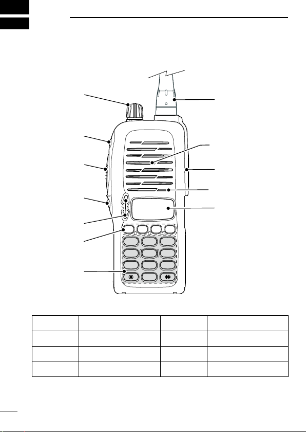
1 PANEL DESCRIPTION ....................................................... 1−3
■ Switches, controls, keys and connectors ..............................1
■ Function display ....................................................................3
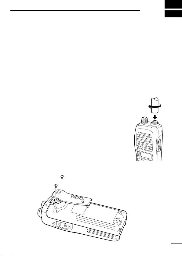
2 ACCESSORIES........................................................................4
■ Accessory attachment...........................................................4
3 BATTERY PACKS ............................................................. 5−10
■ Battery pack replacement .....................................................5
■ Battery cautions ....................................................................6
■ Battery charging....................................................................7
■ Charging caution...................................................................9
■ Battery case (Option)..........................................................10
4 PROGRAMMABLE FUNCTIONS ................................... 11−15
■ General ...............................................................................11
5 CONVENTIONAL OPERATION...................................... 16−18
■ Receiving and transmitting..................................................16
■ Call procedure.....................................................................17
■ Tx code channel selection...................................................18
■ Manual 5-tone codes ..........................................................18
■ Transmitting notes ...............................................................18

iv
6 OTHER FUNCTIONS .............................................................19
■ DTMF PAGER/CODE SQUELCH .......................................19
7 MAINTENANCE .....................................................................20
■ Optional unit installation......................................................20
8 CLONING ...............................................................................21
■ Cloning................................................................................21
9 OPTIONS......................................................................... 23−24

1
PANEL DESCRIPTION
1
■Switches, controls, keys and connectors
2
3
45
6
7 8 9
0
1
P0P1P2P3
Speaker
Mic
i
o
!0
q
w
e
r
y
u
t
DProgrammable key reference
S1 (Red) P0
S2 (Black) P1
YP2
ZP3

2
1
PANEL DESCRIPTION
qVOLUME CONTROL [OFF/VOL]
Rotate to turns power ON and adjusts the audio level.
w DEALER-PROGRAMMABLE KEY [S1 (Red)]
ePTT SWITCH [PTT]
Push and hold to transmit; release to receive.
r DEALER-PROGRAMMABLE KEY [S2(Black)]
tUP/DOWN KEYS [Y]/[Z]
Push to select the operating channel.
y DEALER-PROGRAMMABLE KEYS [P0]/[P1]/[P2]/[P3]
Can each be programmed for one of several functions by your
Icom Dealer.
u10-KEY PAD (IC-F3GT/IC-F4GT only)
Used to enter DTMF codes, the operating channel, etc.
iANTENNA CONNECTOR
Connects the supplied antenna.
o[SP]/[MIC] JACK
Connect optional speaker-microphone.
!0 FUNCTION DISPLAY
Displays the following information:
• CH number.
• 5-tone indication.
• Low-battery indication.
• DTMF numbers.
• Low-power indication.
• Skip-Ch indication.
• Audible indication.
NOTE: Above functions depend on pre-setting.

PANEL DESCRIPTION
1
3
■Function display
q w e r t y u i
o
qTRANSMIT INDICATOR
Appears while transmitting.
wBUSY INDICATOR
Appears while receiving a signal or when the squelch is open.
eLOW POWER INDICATOR (p. 12)
Appears when low output power is selected.
rSCRAMBLER INDICATOR
Appears while the voice scrambler function is activated.
tKEY LOCK INDICATOR (p. 11)
Appears while the key lock function is turned ON.
yBELL INDICATOR
Appears or blinks when a 2/5Tone call is received.
uAUDIBLE INDICATOR
Appears while the monitor function is turned ON. (CTCSS and
DTCS mutes are released.)
iLOW BATTERY INDICATOR
- When “ ” appears, battery capacity is low and transmitting is
impossible.
- When “ ” flashes, battery capacity is nearly exhausted.
oALPHANUMERIC INDICATOR
Displays an operating channel number, channel name, DTMF
code, etc.

2
ACCESSORIES
4
■Accessory attachment
DSupplied accessories
The following accessories are supplied. Qty.
• Battery pack ................................................................................ 1
• Flexible antenna .......................................................................... 1
• Belt clip (with screws).................................................................. 1
• 2251 OPT sheet*......................................................................... 1
*See p. 20 for details.
DAntenna
The antenna screws onto the transceiver as illus-
trated right.
Keep the jack cover attached when jacks are not in
use to avoid bad contacts.
DBelt clip
Attach the belt clip to the transceiver as illustrated below.
Use the supplied screws only.

5
3BATTERY PACKS
■Battery pack replacement
Before replacing the battery pack, the volume control MUST be ro-
tated fully counterclockwise, until a click is heard, to turn the power
OFF.
• Slide the battery release forward, then pull the battery pack up-
ward with the transceiver facing away from you.
DBATTERY PACKS
Battery
pack Voltage Capacity
Charging period
Battery life*1
BC-146
BC-119N or
BC-121N
with AD-101
BP-208N*2Battery case for AA
(LR6) × 6 alkaline N/A N/A —*3
BP-209N 7.2 V 1100 mAh 12 hrs. 1.5 hrs. 8 hrs.
BP-210N 7.2 V
1500 mAh
(minimum) 18.5 hrs. 2.0 hrs. 11 hrs.
1650 mAh
(typical)
BP-222N 7.2 V 600 mAh 6.5 hrs. 1.0 hrs. 4.5 hrs.
*1Operating periods are calculated under the following conditions;
Tx : Rx : standby = 5 : 5 : 90
*2Output power is automatically reduced to 1 W to retains sufficient power
in case of emergency, etc.
*3 Operating period depends on the alkaline cells used.

6
3
BATTERY PACKS
■Battery cautions
RDANGER! NEVER short the terminals of the battery pack
(or charging terminals of the transceiver). Also, current may flow
into nearby metal objects such as a necklace, so be careful when
placing battery packs (or the transceiver) in handbags, etc.
Simply carrying with or placing near metal objects such as a neck-
lace, etc. may cause shorting. This may damage not only the bat-
tery pack, but also the transceiver.
RDANGER! NEVER incinerate used battery packs. Internal
battery gas may cause an explosion.
RWARNING! NEVER immerse the battery pack in water. If the
battery pack becomes wet, be sure to wipe it dry BEFORE attach-
ing it to the transceiver.
Clean the battery terminals to avoid rust or miss contact.
Keep battery terminals clean. It’s a good idea to clean battery ter-
minals once a week.
If your battery pack seems to have no capacity even after being
charged, completely discharge it by leaving the power ON over-
night. Then, fully charge the battery pack again. If the battery pack
still does not retain a charge (or only very little charge), a new bat-
tery pack must be purchased. (p. 5)

7
3BATTERY PACKS
■Battery charging
DRapid charging with the BC-144N
The optional BC-144N provides rapid charging of the battery pack.
The following items are additionally required:
• AD-99N* and an AC adapter (not supplied with some versions).
*Supplied with the charger.
BC-144N
+ AD-99N
Insert together with
the AD-99N.
Check the orienta-
tion of the AD-99N
for correct charging.
Turn power OFF.
DSpacer combination.
• Be sure to attach the spacer (Spacer B/
C) to the adapter (Spacer A) with the
orientation as illustrated in the diagram
at right.
• Attach the spacer (Spacer B/C) to
the adaptor with the orientation of the
stamp “ ” pointing up.
NOTE: Push the notch carefully when
removing the spacer from the adaptor.
The BC-144N cannot
be used in a vehicle,
because the charger
requires 16 V DC
input.
Check orientation
and
Spacer A
Spacer B/C

8
3
BATTERY PACKS
DRapid charging with the BC-121N+AD-101
The optional BC-121N allows up to 6 battery packs to be charged
simultaneously.
The following items are additionally required.
• Six AD-101 (The spacer is supplied with the AD-101.)
• An AC adapter (purchase separately).
AC adapter
(Purchase
separately)
Charge indicator
(each indicator functions
independently)
Insert together with the
spacer.
Check the orientation of the
spacer for correct charging.
Turn power OFF.
DRegular charging with
the BC-137 #11/BC-146
The optional BC-137
#11
or BC-146 provides regular
charging of the battery pack.
The following item is addi-
tionally required:
•
AD-99N* and an AC adapter
(purchase separately).
*Supplied with the charger.
BC-137 #11
or BC-146
Insert together
with AD-99N.
Check the orienta-
tion of AD-99N for
correct charging.
Turn power OFF.

9
3BATTERY PACKS
■Charging caution
Prior to using the transceiver for the first time, the battery pack
must be fully charged for optimum life and operation.
• Recommended temperature range for charging:
Between +10°C and +40°C.
• Use the optional charger (BC-119N/BC-121N/BC-144N for rapid
charging, BC-137 #11/BC-146 for regular charging) only. NEVER
use other manufacturers’ chargers.
The battery pack contains a rechargeable battery.
Charge the battery pack before first operating the transceiver, or
when the battery pack becomes exhausted.
If you want to prolong the battery life, the following points should
be observed:
• Avoid over charging. The charging period should be less than
20 hours.
• Use the battery pack until it becomes almost completely ex-
hausted under normal conditions. We recommend battery charg-
ing after transmitting becomes impossible.
DBattery pack life
When the operating period becomes extremely short even after
charging the battery pack fully, a new battery pack is needed.

10
3
BATTERY PACKS
■Battery case (Option)
When using the optional battery case, install 6 × AA (LR6) size
alkaline batteries as illustrated below.
NOTE: Output power is automatically reduced to 1 W to retains suf-
ficient power in case of emergency, etc.
CAUTIONS:
• When installing batteries, make sure they are all the same
brand, type and capacity. Also, do not mix new and old batteries
together.
• Keep the battery terminals clean. It’s a good idea to clean the
battery terminals once a week.
• Never incinerate used battery cells since internal battery gas
may cause them to rupture.
• Never expose a detached battery case to water. If the battery
case gets wet, be sure to wipe it dry before using it.

■General
In the following explanations, programmable function names are
bracketed, the specific switch used to activate the function depends
on programming.
DKEYPAD LOCK FUNCTION
This function locks access to all programmable switches (except
the switch assigned for the lock function).
Push and hold the [LOCK] switch for 1 sec. to toggle the lock func-
tion ON and OFF.
• “ ”appears while the lock function is ON.
• This function may be inhibited on some channels.
DPRIORITY CHANNEL
This function is used to select a pre-programmed channel at the
push of a switch.
Push the [PRIORITY] switch to select the priority channel.
• “PRIO” appears briefly, then the priority channel is automatically se-
lected.
DSCAN FUNCTION
The scan function allows you to search a pre-programmed group of
channels for signals.
Push the [SCAN] switch to start/stop scan.
• Scan pauses on a channel when receiving a signal.
• Depending on programming, a message may appear while scanning.
• “Lockout SCAN” (pre-programmed list SCAN) or “Priority SCAN” can
be pre-programmed.
• When the “Power-save function” is activated, the transceiver checks
all pre-programmed channels then returns to the “Power-save func-
tion” again.
11
4PROGRAMMABLE FUNCTIONS

12
4
PROGRAMMABLE FUNCTIONS
DHIGH/LOW OUTPUT POWER
This function selects high or low output power for a channel.
Push the [HIGH/LOW] switch to toggle the transmit output power
between high and low.
• “LOW” appears when low output power is selected.
DSCRAMBLER FUNCTION
(An UT-109 #01* or UT-110 #01* is required.)
This function provides higher communication security.
UT-109 : Non-rolling type. 32 code numbers are available.
UT-110 : Rolling type. 1020 (4 groups ×255) code numbers are
available.
Push the [SCRM] switch to toggle the function ON and OFF.
NOTE: NEVER use #02 High AF level version of the scrambler
unit, as they are not compatible.
DBEEP FUNCTION
This function provides confirmation beep tones when pushing
switches.
Push the [BEEP] switch to toggle the function ON and OFF.

13
4PROGRAMMABLE FUNCTIONS
DMONITOR AUDIBLE FUNCTION
The monitor function allows you to open the transceiver’s squelch
manually to check whether a channel is busy or not. The trans-
ceiver has 2 conditions for receive standby:
All signals are
received.
2
3
45
6
7 8 9
0
1
P0P1P2P3
Audible condition:
This condition mutes audio ONLY when no carrier
is present. You can receive (or monitor) any signals
on a channel.
• Push and hold the [MONI/AUDI], switch to select
the audible condition.
Any audio mute functions are cancelled while push-
ing the [MONI/AUDI] switch.
2
3
45
6
7 8 9
0
1
P0P1P2P3
Only signals
containing the
proper tone
are received.
Inaudible condition:
This condition mutes ALL signals except those
directed to you. Therefore you should check a
channel’s condition (busy or not) with the monitor
function before transmitting.
• Push the [MONI/AUDI] switch momentarily to se-
lect the inaudible condition.
DTALK AROUND
The talk around function changes duplex channels to simplex chan-
nels.
• Duplex allows you to contact your base station, repeaters, etc.
• Simplex allows you to contact other portable transceivers directly
(portable-to-portable contact).
Push the [TALK AROUND] switch one or more times to toggle the
function ON and OFF.

14
4
PROGRAMMABLE FUNCTIONS
DDTMF TRANSMISSION
This function allows you to send a pre-programmed DTMF code to
control a repeater, open another transceiver’s squelch, etc.
Manual transmission:
Push desired digit keys in sequence while pushing [PTT].
• Pushing [PTT] may not be necessary depending on programming.
Automatic pre-programmed transmission:
qPush the [DTMF] switch to select DTMF autodial mode, then
push [Y] or [Z] to select the desired channel.
wPush the [DTMF] switch once more to send a DTMF code.
D DTMF RE-DIAL FUNCTION
This function allows you to transmit the last-used DTMF code at
the push of a key.
Push the [DTMF RE-DIAL] switch momentarily to activate the func-
tion.
• The previously transmitted DTMF code is automatically transmitted.
• If no code has been transmitted since turning the power ON, this func-
tion does not activate.
DEMERGENCY FUNCTION
The emergency function allows you to send your ID quickly and
easily to your Base Station, etc. in case of emergency.
Push and hold the [EMERGENCY] switch for 1 sec. to activate the
emergency function.
• The transceiver selects a pre-programmed channel, then sends an
emergency signal to your Base Station.
• The pre-programmed channel remains selected until a control signal
is received from the Base Station, or power is turned OFF.
• The emergency call is repeatedly transmitted at pre-programmed in-
tervals.

15
4PROGRAMMABLE FUNCTIONS
DDISPLAY LIGHTING
The function display has 3 backlight conditions.
OFF : No backlight.
AUTO : When any key is pushed, the backlight turns ON
for 5 sec. automatically.
CONTINUOUS : Backlight stays ON continuously.
Other manuals for IC-F3GT
2
This manual suits for next models
3
Table of contents
Other Icom Transceiver manuals