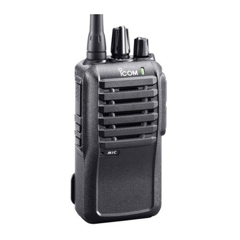
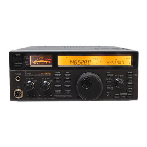
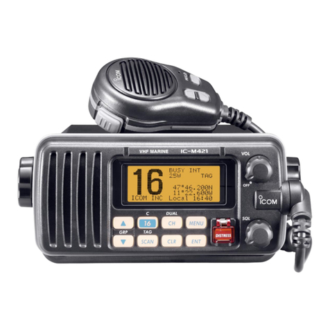
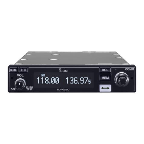
Icom IC-F24 Building instructions

SERVICE MANUAL
ADDENDUM
CONTENTS
PARTS LIST. . . . . . . . . . . . . . . . . . . . . . . . . . . . . . . . . . . . . . . . . 1
BOARD LAYOUTS. . . . . . . . . . . . . . . . . . . . . . . . . . . . . . . . . . . . 6
VOLTAGE DIAGRAM. . . . . . . . . . . . . . . . . . . . . . . . . . . . . . . . . . 8
Jun. 2005

SERVICE
MANUAL
UHF TRANSCEIVERS
S-14116IZ-C1-q
Jun. 2005

INTRODUCTION
This service manual describes the latest service
information for the IC-F24/IC-F24S/IC-F25/IC-F25S UHF
TRANSCEIVER at the time of publication.
DANGER
NEVER connect the transceiver to an AC outlet or to a DC
power supply that uses more than 8 V. Such a connection
could cause a fire or electric hazard.
DO NOT expose the transceiver to rain, snow or any liquids.
DO NOT reverse the polarities of the power supply when
connecting the transceiver.
DO NOT apply an RF signal of more than 20 dBm (100mW)
to the antenna connector. This could damage the trans-
ceiver's front end.
ORDERING PARTS
Be sure to include the following four points when ordering
replacement parts:
1. 10-digit order numbers
2. Component part number and name
3. Equipment model name and unit name
4. Quantity required
<SAMPLE ORDER>
2260002840 Switch SKHLLFA010 IC-F24 Main unit 5 pieces
8930063350 Lens 2775 Lens IC-F24 Chassis 10 pieces
Addresses are provided on the inside back cover for your
convenience.
1. Make sure the problem is internal before disassembling the transceiver.
2. DO NOT open the transceiver until the transceiver is disconnected from its power source.
3. DO NOT force any of the variable components. Turn them slowly and smoothly.
4. DO NOT short any circuits or electronic parts. An insulated turning tool MUST be used for all adjustments.
5. DO NOT keep power ON for a long time when the transceiver is defective.
6. DO NOT transmit power into a signal generator or a sweep generator.
7. ALWAYS connect a 30 dB to 40 dB attenuator between the transceiver and a deviation meter or spectrum analyzer when
using such test equipment.
8. READ the instructions of test equipment thoroughly before connecting equipment to the transceiver.
To upgrade quality, all electrical or mechanical parts and
internal circuits are subject to change without notice or
obligation.
Icom, Icom Inc. and are registered trademarks of Icom Incorporated (Japan) in the United States, the United Kingdom,
Germany, France, Spain, Russia and/or other countries.
MODEL VERSION SYMBOL CH FREQUENCY
IC–F24
USA–02 US2 16 400–470 MHz
USA–03 US3 16 450–512 MHz
GEN–02 GE2 16 450–470 MHz
GEN–03 GE3 16 450–520 MHz
IC–F24S
USA–02 US2S 2 400–470 MHz
USA–03 US3S 2 450–512 MHz
GEN–02 GE2 2 400–470 MHz
GEN–03 GE3 2 450–520 MHz
IC–F25 EUR–02 EU2 16 400–470 MHz
IC–F25S EUR–02 EU2S 2 400–470 MHz
REPAIR NOTES

TABLE OF CONTENTS
SECTION 1 SPECIFICATIONS
SECTION 2 INSIDE VIEWS
SECTION 3 DISASSEMBLY INSTRUCTIONS
SECTION 4 CIRCUIT DESCRIPITON
4-1 RECEIVER CIRCUITS . . . . . . . . . . . . . . . . . . . . . . . . . . . . . . . . . . . . . . . . . . . . . . . . . . . . . . . 4-1
4-2 TRANSMITTER CIRCUITS . . . . . . . . . . . . . . . . . . . . . . . . . . . . . . . . . . . . . . . . . . . . . . . . . . . 4-2
4-3 PLL CIRCUITS . . . . . . . . . . . . . . . . . . . . . . . . . . . . . . . . . . . . . . . . . . . . . . . . . . . . . . . . . . . . . 4-3
4-4 OTHER CIRCUITS . . . . . . . . . . . . . . . . . . . . . . . . . . . . . . . . . . . . . . . . . . . . . . . . . . . . . . . . . . 4-4
4-5 POWER SUPPLY CIRCUITS . . . . . . . . . . . . . . . . . . . . . . . . . . . . . . . . . . . . . . . . . . . . . . . . . . 4-5
4-6 PORT ALLOCATIONS . . . . . . . . . . . . . . . . . . . . . . . . . . . . . . . . . . . . . . . . . . . . . . . . . . . . . . . 4-5
SECTION 5 ADJUSTMENT PROCEDURES
5-1 PREPARATION . . . . . . . . . . . . . . . . . . . . . . . . . . . . . . . . . . . . . . . . . . . . . . . . . . . . . . . . . . . . . 5-1
5-2 CONFIGURATION LISTS FOR ADJUSTMENTS . . . . . . . . . . . . . . . . . . . . . . . . . . . . . . . . . . . 5-2
5-3 SOFTWARE ADJUSTMENTS . . . . . . . . . . . . . . . . . . . . . . . . . . . . . . . . . . . . . . . . . . . . . . . . . 5-3
SECTION 6 PARTS LIST
SECTION 7 MECHANICAL PARTS AND DISASSEMBLY
SECTION 8 SEMI-CONDUCTOR INFORMATION
SECTION 9 BOARD LAYOUTS
9-1 MAIN UNIT . . . . . . . . . . . . . . . . . . . . . . . . . . . . . . . . . . . . . . . . . . . . . . . . . . . . . . . . . . . . . . . . 9-1
9-2 ANT UNIT . . . . . . . . . . . . . . . . . . . . . . . . . . . . . . . . . . . . . . . . . . . . . . . . . . . . . . . . . . . . . . . . . 9-1
9-3 CONNECT UNIT . . . . . . . . . . . . . . . . . . . . . . . . . . . . . . . . . . . . . . . . . . . . . . . . . . . . . . . . . . . . 9-1
SECTION 10 BLOCK DIAGRAM
SECTION 11 VOLTAGE DIAGRAM
11-1 MAIN UNIT . . . . . . . . . . . . . . . . . . . . . . . . . . . . . . . . . . . . . . . . . . . . . . . . . . . . . . . . . . . . . . . . 11-1

1 - 1
SECTION 1 SPECIFICATIONS
GENERAL
• Frequency coverage : 400–470 MHz [USA–02], [GEN–02], [EUR]
450–512 MHz [USA–03]
450–520 MHz [GEN–03]
• Type of emission :
• Number of conventional channels : 2 ch (IC-F24S/F25S), 16 ch (IC-F24/F25)
• Antenna impedance : 50 Ω(nominal)
• Operating temperature range : –30˚C to +60˚C (–22˚F to +140˚F) [USA], [GEN]
–25˚C to +55˚C [EUR]
• Power supply requirement : 7.2 V DC nominal (negative ground)
• Current drain (at 7.2 V DC ; approx.) :
• Dimensions (projections not included) : 53(W)×120(H)×38(D) mm; 23⁄32(W)×423⁄32(H)×11⁄2(D) in
• Weight (Including BP-231) : Approximately 260 g (93⁄16 oz)
TRANSMITTER
• Output power (at 7.2 V DC) : 4 W
• Modulation :Variable reactance frequency modulation
• Maximum permissible deviation : ±5.0 kHz (Wide), ±4.0 kHz (Middle), ±2.5 kHz (Narrow)
• Frequency error : ±2.5 ppm
• Spurious emissions : 70 dB (min.) [USA], [GEN]
0.25 µW (≤1 GHz), 1.0 µW (>1 GHz) [EUR]
• Adjacent channel power : 70 dB min. (75 dB typical) for Wide
70 dB min. (73 dB typical) for Middle
60 dB min. (68 dB typical) for Narrow
• Audio harmonic distortion : 3% typical (1 kHz, 40% deviation)
• Hum and Noise ([USA], [GEN]) : 40 dB min. (46 dB typical) for Wide
(without CCITT filter) 34 dB min. (40 dB typical) for Narrow
• Residual modulation ([EUR] only) : 45 dB min. (55 dB typical) for Wide
(with CCITT filter) 43 dB min. (53 dB typical) for Middle
40 dB min. (50 dB typical) for Narrow
• Limiting charact of modulator : 60–100% of maximum deviation
• Microphone impedance : 2.2 kΩ
RECEIVER
• Receive system : Double conversion superheterodyne system
• Intermediate frequencies : 1st IF: 46.35 MHz, 2nd IF: 450 kHz
• Sensitivity : 0.25 µV (–119 dBm) typical at 12 dB SINAD [USA], [GEN]
–4 dBµV (–111 dBm) emf typical at 20 dB SINAD
[EUR]
• Squelch sensitivity (at threshold) : 0.25 µV typical [USA], [GEN]
–4 dBµV emf typical [EUR]
• Adjacent channel selectivity : 70 dB min. (75 dB typical) for Wide
70 dB min. (73 dB typical) for Middle
60 dB min. (65 dB typical) for Narrow
• Spurious response : 70 dB min.
• Intermodulation rejection ratio : 70 dB min. (74 dB typical) [USA], [GEN]
65 dB min. (67 dB typical) [EUR]
• Hum and Noise ([USA], [GEN] only) : 40 dB min. (45 dB typical) for Wide
(without CCITT filter) 34 dB min. (40 dB typical) for Narrow
• Hum and Noise ([EUR] only) : 45 dB min. (55 dB typical) for Wide
(with CCITT filter) 43 dB min. (53 dB typical) for Middle
40 dB min. (50 dB typical) for Narrow
• Audio output power : 0.5 W typical at 5% distortion with an 8 Ωload
• Output impedance (Audio) : 8 Ω
Specifications are measured in accordance with EIA-152-C/204D, TIA-603 or EN 300 086.
All stated specifications are subject to change without notice or obligation.
VERSION WIDE MIDDLE NARROW
[USA], [GEN] 16K0F3E (25.0 kHz) N/A
11K0F3E (12.5 kHz)
[EUR]
14K0F3E (20.0 kHz) 8K50F3E (12.5 kHz)
RECEIVING TRANSMITTING
Stand-by Max. audio
High (at 4 W) Low (at 1 W)
75 mA 300 mA 1.6 A 0.8 A
SECTION 7 MECHANICAL PARTS AND DISASSEMBLY
7 - 1
Screw abbreviations B0, BT: Self-tapping
ZK: Black
SUS: Stainless
NI-ZU: Nickel-zinc
7-1 CABINET PARTS
[MAIN UNIT]
[CHASSIS PARTS]
MP4
EP2
MP1
MP2
MP3
EP1
[ACCESSORIES]
REF. ORDER. NO. DESCRIPTION QTY.
EP1 3310002311 FA-SC25U-1 [US2], [US2S], [EU2] 1
[EU2S], [GE2], [GE2S]
3310002291 FA-SC57U-1 [US3], [US3S] 1
[GE3], [GE3S]
EP2 0800007541 BP-231 ACC-1
MP1 8010019540 MB-94 ACC 1
MP2 8210020560 2721 JACK PANEL 1
MP3 8810004860 Screw M2 x 6 ZK 2
MP4 8930051290 2251 opt sheet 1
REF. ORDER. NO. DESCRIPTION QTY.
J2 6450001680 HSJ1122010010 1
J3 6450002250 HSJ1456-010320
R226 7210003061 TP76N00N-15F-A103-2251A 1
S1 2260002840 SKHLLFA010 1
S4 2250000490 TP70TF5163-15.9F-2775 [F24S], [F25S] 1
only
MP4 8510016580 2775 shield plate 1
MP5 8510016770 2776 earth plate 1
MC1 7700002540 SKP-4538 1
REF. ORDER. NO. DESCRIPTION QTY.
S1 2260002870 AS-243-A13 [F24S], [F25S]only 1
SP1 2510001060 K036NA500-47 1
W1 8900009640 OPC-963 1
W2 8900009640 OPC-963 [F24S], [F25S]only 1
J1 6910015910 Antenna connector-104 1
J2 6910015860 IMSA-6277S-02A-G 1
MP1 8010019690 2775 chassis 1
MP2 8210020920 2775 front panel 1
MP8 8210020550 2721 rear panel 1
MP9 8930063350 2775 lens 1
MP10 8610011930 Knob N-318 1
MP11 8610012130 Knob N-323 [F24], [F25] 1
MP13 8930063330 2775 B-main seal [F24], [F25] 1
8930063330 2775 A-main seal [F24S], [F25S] 1
MP14 8930063060 2721 terminal rubber 1
MP16 8930063400 2775 side plate 1
MP17 8930063410 2775 B-top plate [F24], [F25] 1
8930063410 2775 A-top plate [F24S], [F25S] 1
MP20 8930043760 1923 mic seal 1
MP21 8930059360 2600 release button 1
MP22 8930063390 2775 release plate 1
MP25 8830001720 2721 antenna nut 1
MP26 8810009220 Scerw B0 2 x 8 ZK (BT) 2
MP27 8810009560 Scerw M2 x 6 ZK 2
MP28 8810009510 Scerw M2 x 4 NI-ZU (BT) 9
MP29 8810009510 Scerw M2 x 4 NI-ZU (BT) 1
MP30 8810009510 Scerw M2 x 4 NI-ZU (BT) 1
MP31 8810010160 Scerw M3 x 5 SUS ZK 1
MP32 8930051290 2251 opt sheet 1
MP33 8930042350 1922 mic sheet 1
MP34 8930056540 Spring (AH) 2
MP35 8830001700 VR nut (Q) 1
MP36 8830001700 VR nut (Q) 1
MP37 8830001740 VR nut (S) [F24S], [F25S]only 1

1-1-32, Kamiminami, Hirano-ku, Osaka S-14116IZ-C1-q
Printed in Japan
© 2004-2005 Icom Inc.

Icom IC-F24 F-25 Service Manual
Other manuals for IC-F24
1
This manual suits for next models
3
Table of contents
Other Icom Transceiver manuals