Icom IC-F34GT User manual

INSTRUCTION MANUAL
iF44GT/GS
UHF TRANSCEIVER
iF34GT/GS
VHF TRANSCEIVER
The photo shows the 10-key
version UHF transceiver.

i
RDANGER! NEVER short the terminals of the bat-
tery pack.
RDANGER! Use and charge only specified Icom battery
packs with Icom radios or Icom chargers. Only Icom battery
packs are tested and approved for use with Icom radios or
charged with Icom chargers. Using third-party or counterfeit
battery packs or chargers may cause smoke, fire, or cause
the battery to burst.
RWARNING! NEVER hold the transceiver so that
the antenna is very close to, or touching exposed parts of
the body, especially the face or eyes, while transmitting. The
transceiver will perform best if the microphone is 5 to 10 cm
away from the lips and the transceiver is vertical.
RWARNING! NEVER operate the transceiver with
a headset or other audio accessories at high volume levels.
Hearing experts advise against continuous high volume oper-
ation. If you experience a ringing in your ears, reduce the
volume level or discontinue use.
RWARNING! NEVER operate the transceiver while
driving a vehicle. Safe driving requires your full attention—
anything less may result in an accident.
PRECAUTIONS
READ ALL INSTRUCTIONS carefully and com-
pletely before using the transceiver.
SAVE THIS INSTRUCTION MANUAL — This
instruction manual contains important operating instruc-
tions for the IC-F34GT/IC-F34GS VHF TRANSCEIVER and
IC-F44GT/IC-F44GS UHF TRANSCEIVER.
IMPORTANT
Icom, Icom Inc. and the Icom logo are registered trademarks of Icom
Incorporated (Japan) in Japan, the United states, the United Kingdom,
Germany, France, Spain, Russia and/or other countries.
WORD DEFINITION
RDANGER! Personal death, serious injury or an explo-
sion may occur.
RWARNING! Personal injury, fire hazard or electric
shock may occur.
CAUTION Equipment damage may occur.
NOTE
If disregarded, inconvenience only. No risk
of personal injury, fire or electric shock.
EXPLICIT DEFINITIONS

ii
PRECAUTIONS
CAUTION: MAKE SURE the flexible antenna and
battery pack are securely attached to the transceiver, and that
the antenna and battery pack are dry before attachment.
Exposing the inside of the transceiver to water will result in
serious damage to the transceiver.
DO NOT operate the transceiver near unshielded electri-
cal blasting caps or in an explosive atmosphere.
DO NOT push [PTT] when not actually intending to transmit.
DO NOT use or place the transceiver in direct sunlight or in
areas with temperatures below –25°C or above +55°C.
The basic operations, transmission and reception of the trans-
ceiver are guaranteed within the specified operating tempera-
ture range. However, the LCD display may not be operate
correctly, or show an indication in the case of long hours of
operation, or after being placed in extremely cold areas.
DO NOT modify the transceiver. The transceiver warranty
does not cover any problems caused by unauthorized modi-
fication.
DO NOT use harsh solvents such as benzine or alcohol
when cleaning, as they will damage the transceiver surfaces.
BE CAREFUL! The transceiver will become hot when
operating it continuously for long periods of time.
KEEP the transceiver away from the heavy rain, and Never
immerse it in the water. The transceiver construction is water
resistant, not waterproof.
MAKE SURE to turn the transceiver power OFF before
connecting the supplied/optional equipment.

iii
TABLE OF CONTENTS
IMPORTANT.......................................................................... i
EXPLICIT DEFINITIONS....................................................... i
PRECAUTIONS.................................................................... ii
TABLE OF CONTENTS....................................................... iii
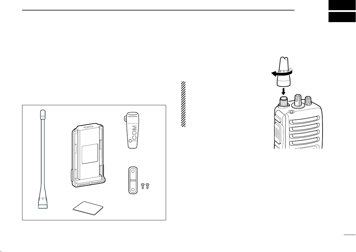
1 ACCESSORIES ...........................................................1–3
Supplied accessories
■...................................................1
Accessory attachments
■................................................1
2 PANEL DESCRIPTION..............................................4–10
Front panel
■...................................................................4
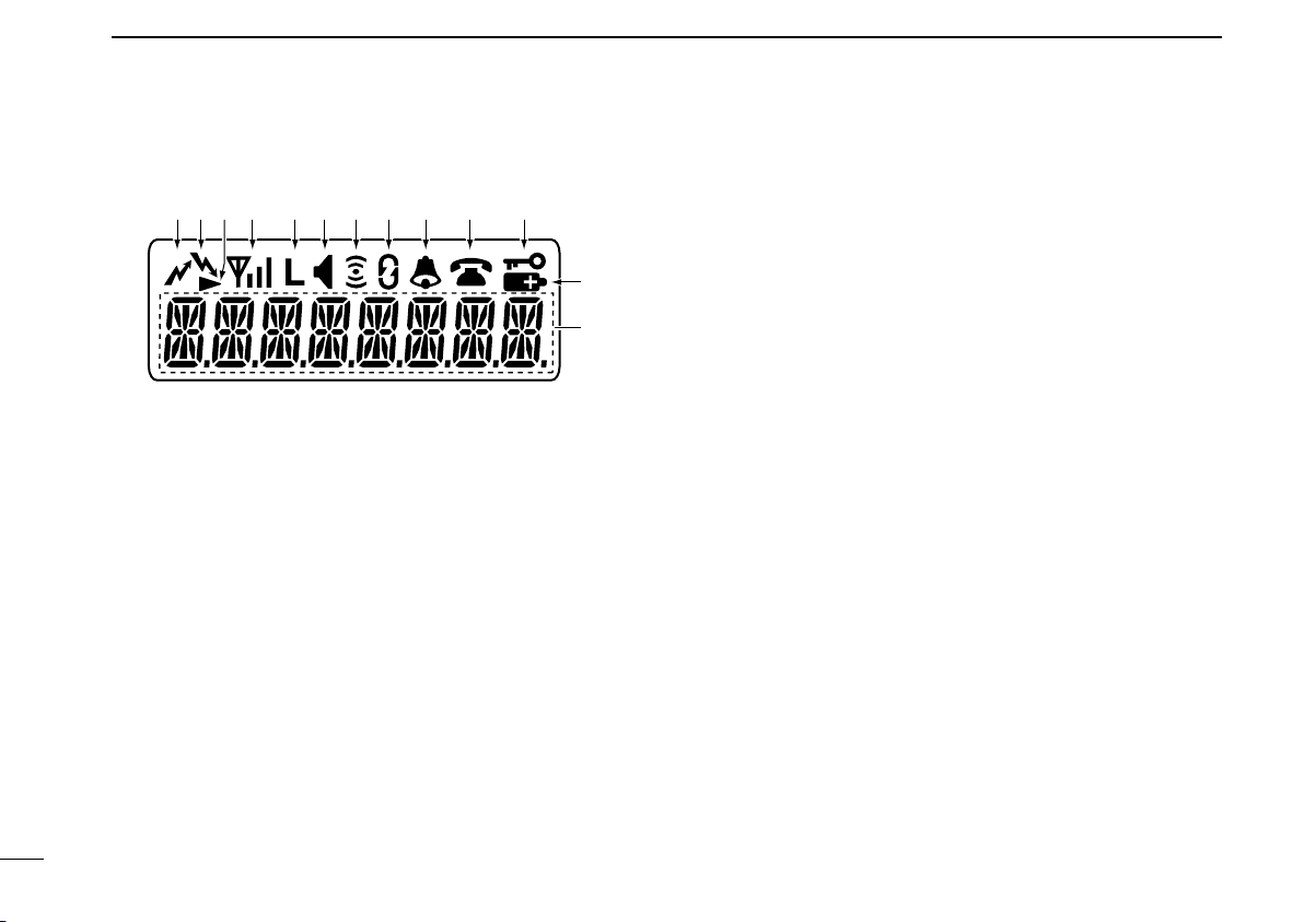
Function display
■...........................................................6
Programmable function keys
■........................................7
3 BASIC OPERATION................................................11–15
Turning power ON
■......................................................11
Channel selection
■......................................................11
Call procedure
■............................................................12
Receiving and transmitting
■.........................................12
User set mode
■............................................................15
Scrambler function
■.....................................................15
4 BIIS OPERATION ....................................................16–27
Default setting
■............................................................16
Receiving a call
■..........................................................16
Transmitting a call
■......................................................18
Receiving a message
■.................................................20
Transmitting a status
■..................................................22
Transmitting an SDM
■..................................................23
Position data transmission
■.........................................25
Printer connection
■......................................................25
Digital ANI
■..................................................................25
Auto emergency transmission
■....................................26
Stun function
■..............................................................26
BIIS indication
■............................................................26
Priority A channel selection
■........................................26
Man Down Emergency Call
■........................................27
5 OPTIONAL UNIT INSTALLATION ..........................28–29
Optional unit installation
■.............................................28
UT-109 and UT-110 installation
■..................................29
6 BATTERY CHARGING ............................................30–34
Caution
■.......................................................................30
Optional battery chargers
■...........................................32
7 BATTERY CASE............................................................35
Optional battery case (BP-240)
■..................................35
8 SWIVEL BELT CLIP ................................................36–37
MB-93 contents
■..........................................................36
To attach
■....................................................................36
To detach
■...................................................................37
9 OPTIONS.................................................................38–39
10 COUNTRY CODE LIST .................................................40

1
1
ACCESSORIES
Supplied accessories
■
The following accessories are supplied: Qty.
qFlexible antenna...............................................................1
wBattery pack.....................................................................1
eBelt clip ............................................................................1
rUnit cover (double-sided tape)*........................................1
tJack cover (with screws) ............................................ 1 set
*Use the unit cover as a spare. Ask your dealer for details.
Accessory attachments
■
DFlexible antenna
Connect the supplied flexible anten-
na to the antenna connector.
CAUTION:
• NEVER carry the transceiver by
holding only the antenna.
• DO NOT connect the antenna
other than listed on page 39.
• Transmitting without an antenna
may damage the transceiver.
qw
r
e
t

2
1ACCESSORIES
DBattery pack
To attach the battery pack:
Slide the battery pack in the direction of the arrow (q), then
lock it with the battery release button.
• Slide the battery pack until the battery release button makes a ‘click’
sound.
To remove the battery pack:
Push the battery release button in the direction of the arrow
(w) as shown below. The battery pack is then removed.
NEVER remove or attach the battery pack when the trans-
ceiver is wet or soiled. This may result water or dust getting
into the transceiver/battery pack and may result in the
transceiver being damaged.
DBelt clip
To attach the belt clip:
qRemove the battery pack if it is attached.
wSlide the belt clip in the direction of the arrow, until the
belt clip is locked and makes a ‘click’ sound.
To detach the belt clip:
qRemove the battery pack if it is attached.
wPinch the clip (q), and slide the belt clip in the direction
of the arrow (w).
q
w
q
w
NOTE: Keep battery pack terminals clean. It’s a good idea
to occasionally clean them.
Battery release
button
Battery pack

3
1
ACCESSORIES
DJack cover
Attach the jack cover when the optional speaker-microphone
is not used.
To attach the jack cover:
qAttach the jack cover on
the [SP]/[MIC] jack.
wTighten the screws.
To detach the jack cover:
qRemove the screws using
a Phillips screwdriver.
wDetach the jack cover for
the optional equipment
connection.
q
w
q
w

4
2PANEL DESCRIPTION
Front panel
■
qROTARY SELECTOR
Rotate to select the pre-programmed memory channels
or the operating bank.
(Depending on the pre-setting)
wVOLUME CONTROL [VOL]
Rotate to turn the power ON/OFF and adjust the audio
level.
eDEALER-PROGRAMMABLE KEY [RED]
Desired function can be programmed by your dealer
.
(p. 7)
r[SP]/[MIC] JACK
Connect the optional speaker-microphone.
tFUNCTION DISPLAY
Displays a variety of information such as an operating
channel number/name, 2/5-tone code, DTMF numbers,
selected function, etc.
yDEALER-PROGRAMMABLE KEYS [P0] to [P3]
Desired functions can be programmed independently by
your dealer. (p. 7)
[SP]/[MIC] jack cover
NOTE: Attach the [SP]/[MIC]
jack cover when the optional
speaker-microphone is not used.
(See page 3 for details)
it
r
q
e
u
y
w
o
!0
!1
10-keypad version

5
2
PANEL DESCRIPTION
u10-KEYPAD (Depending on version)
The keypad allows you to enter digits to:
• Select memory channels
• Select tone channels
• Select DTMF codes (during transmit)
• Set TX codes
• Set BIIS status number
• Input text message for SDM operation
• Start up with the password
iUP/DOWN KEYS
➥Push to select an operating channel.
➥Push to select a TX code channel after pushing
[TX CODE CH SELECT].
➥Push to select a DTMF channel after pushing [DTMF].
➥Push to select a scan group after pushing and holding
[SCAN].
➥Push to select a BIIS code, status number or SDM
after pushing [DIGITAL].
*Desired functions can be programmed independently by your
dealer. (p. 7)
oPTT SWITCH [PTT]
➥Push and hold to transmit; release to receive.
➥Push to transmit the call during MSK operation,
depending on the setting.
!0 MONITOR KEY
➥Mute and release the CTCSS (DTCS) or 2-tone
squelch mute. Open any squelch/deactivate any mute
while pushing this key. (LMR operation only)
➥Activates one of (or two of) the following functions on
each channel independently.
(PMR or BIIS PMR operation only)
• Push and hold the key to unmute the channel (audio is
emitted; ‘audible’ condition).
• Push the key to toggle the mute and unmute conditions
(toggles ‘audible’ and ‘inaudible’).
• Push the key to mute the channel (sets to ‘inaudible’ only).
• Push the key to unmute the channel (sets to ‘audible’ only).
• Push the key after communication is nished to send a ‘reset
code.’
• Push the key after communication is nished to send a ‘clear
down code’ during BIIS operation on an MSK channel.
NOTE: The unmute condition (‘audible’ conditions)
may automatically return to the mute condition
(‘inaudible’ condition) after a specied period.
*Desired function can be programmed by your dealer. (p. 7)
!1 ANTENNA CONNECTOR
Connects the supplied antenna.

6
2PANEL DESCRIPTION
Function display
■
qTRANSMIT INDICATOR
Appears while transmitting.
wBUSY INDICATOR
Appears while the channel is busy.
eSCROLL INDICATOR
Appears when a received SDM including more than 8
characters is displayed.
rSIGNAL STRENGTH INDICATOR
Indicates relative signal strength level.
tLOW POWER INDICATOR
Appears when low output power is selected.
• When the battery power decreases to a specified level, low
power is selected automatically.
yAUDIBLE INDICATOR
➥ Appears when the channel is in the ‘audible’ (unmute)
condition.
➥ Appears when the specified 2/5-tone/BIIS code is
received.
uCOMPANDER INDICATOR
Appears when the compander function is activated.
iSCRAMBLER INDICATOR
Appears when the voice scrambler function is activated.
oBELL INDICATOR
Appears/blinks when the specific 2/5-tone/BIIS code is
received, according to the pre-programming.
!0 CALL CODE MEMORY INDICATOR
Appears when the call code memory is selected.
!1 KEY LOCK INDICATOR
Appears during the key lock function is ON.
!2 BATTERY INDICATOR
Appears or blinks when the battery power decreases to a
specified level.
!3 ALPHANUMERIC DISPLAY
Displays an operating channel number, channel name,
Set mode contents, DTMF code, etc.
q !1!0oiuytrew
!2
!3

7
2
PANEL DESCRIPTION
Programmable function keys
■
The following functions can be assigned to [UP], [DOWN],
[P0], [P1], [P2], [P3], [RED] and [MONITOR] programmable
function keys.
Consult your Icom dealer or system operator for details con-
cerning your transceivers programming.
If the programmable function names are bracketed in the fol-
lowing explanations, the specific key is used to activate the
function depends on the programming.
CH UP AND DOWN KEYS
➥Push to select an operating channel.
➥Push to select a transmit code channel after pushing [TX
Code CH Select].
➥Push to select a DTMF channel after pushing [DTMF
Autodial].
➥Push to select a scan group after pushing and holding
[Scan A Start/Stop]/[Scan B Start/Stop].
➥Push to select a BIIS code, status number or SDM after
pushing [Digital].
BANK SELECT KEY
Push this key, then push [CH Up] or [CH Down] to select the
desired bank.
SCAN A KEY
➥ This key’s operation depends on the Power ON Scan set-
ting.
When the power ON scan function is turned OFF;
Push to start and cancel scanning operation. In case of
transmission during scan, cancels scanning.
When the power ON scan function is turned ON;
Push to pause scanning. Scanning resumes after pass-
ing a specified time period. In case of transmission during
scan, pauses scanning. Scanning resumes after passing
a specified time period.
➥Push and hold this key for 1 sec. to indicate the scan
group, then push [CH Up] or [CH Down] to select the
desired group.
SCAN B KEY
➥Push to start and cancel scanning operation. In case of
transmission during scan, pauses scanning. Scanning
resumes after passing a specified time period.
➥Push and hold this key for 1 sec. to indicate the scan
group, then push [CH Up] or [CH Down] to select the
desired group.

8
2PANEL DESCRIPTION
SCAN TAG KEY
Push to add or delete the selected channel to the scan
group.
PRIORITY CHANNEL KEYS
➥Push to select Priority A or Priority B channel.
➥Push and hold [Prio A (Rewrite)] to rewrite the Prio A
channel.
MR-CH 1/2/3/4 KEYS
Push to select an operating channel directly.
MONITOR KEY
➥Mute and release the CTCSS (DTCS) or 2-tone squelch
mute. Open any squelch/deactivate any mute while push-
ing this key. (LMR operation only)
➥Activates one of (or two of) the following functions on
each channel independently: (PMR or BIIS PMR opera-
tion only)
• Push and hold to un-mute the channel (audio is emitted;
‘Audible’ condition).
• Push to mute the channel (sets to ‘Inaudible’ only).
• Push to un-mute the channel (sets to ‘Audible’ only).
• Push after the communication is nished to send a ‘reset
code’.
NOTE: The un-mute condition (‘Audible’ condition) may
automatically return to the mute condition (‘Inaudible‘
condition) after a specified period.
LOCK KEY
Push and hold to electronically lock all programmable keys
except the following:
[Call] (incl. Call A and Call B), [Moni(Audi)] and [Emergency].
OUTPUT POWER SELECTION KEY
Push to select the transmit output power temporarily or per-
manently, depending on the pre-setting.
• Ask your dealer for the output power level for each selection.
C.TONE CHANNEL ENTER KEY
Push to select the continuous tone channel using
[CH Up]/[CH Down] to change the tone frequency/code set-
ting after pushing this key for permanent operation.
TALK AROUND KEY
Turn the talk around function ON and OFF.
• The talk around function equalizes the transmit frequency to the
receive frequency for transceiver-to-transceiver communication.
WIDE/NARROW KEY
Push to toggle the IF bandwidth between wide and narrow.
• The wide passband width can be selected from 25.0 or 20.0 kHz
using the CS-F33G c l o n i n g s o f t w a r e . (PMR or BIIS PMR opera-
tion only) Ask your Dealer for details.

9
2
PANEL DESCRIPTION
DTMF AUTODIAL KEY
➥Push to enter the DTMF channel selection mode. Then
select the desired DTMF channel using [CH Up]/[CH
Down] keys.
➥After selecting the desired DTMF channel, push this key
to transmit the DTMF code.
DTMF RE-DIAL KEY
Push to transmit the last-transmitted DTMF code.
CALL KEYS
Push to transmit a 2/5-tone/BIIS ID code.
• Call transmission is necessary before you call another station
depending on your signalling system.
• [Call A] and/or [Call B] may be available when your system
employs selective ‘Individual/Group’ calls. Ask your dealer which
call is assigned to each key.
EMERGENCY KEYS
➥Push and hold to transmit an emergency call.
➥ When [Emergency Single (Silent)] or [Emergency Repeat
(Silent)] is pushed, an emergency call is transmitted with-
out a beep emission and LCD indication change.
• If you want to cancel the emergency call, push (or push and
hold) the key again before transmitting the call.
• The emergency call is transmitted one time only or repeatedly
until receiving a control code depending on the pre-setting.
TX CODE ENTER KEY (PMR or BIIS PMR operation only)
Push to enter the direct ID code edit mode, for both 5-tone
and MSK. Then set the desired digit using [CH Up]/[CH
Down]/[TX Code CH Up]/[TX Code CH Down] or 10-key-
pad.* (p. 14)
*Depending on version
TX CODE CHANNEL SELECT KEY
➥Push to enter the direct ID code channel selection mode.
Then set the desired channel using [CH Up]/[CH Down]/
[TX Code CH Up] or [TX Code CH Down]. (p. 13)
➥ While in ID code channel selection mode, push for 1 sec.
to enter the ID code edit mode for 5-tone and MSK. Then
set the desired digit using [CH Up]/[CH Down]/[TX Code
CH Up]/[TX Code CH Down] or 10-keypad.* (p. 14)
*Depending on version
TX CODE CHANNEL UP/DOWN KEYS
Push to select a TX code channel directly.
ID MEMORY READ KEY (PMR or BIIS PMR operation only)
➥Recalls detected ID codes.
• Push this key, then push [CH Up]/[CH Down] for selection.
• Up to 5 ID’s are memorized.
➥ Push and hold to erase the selected memorized ID’s.
VOICE SCRAMBLER FUNCTION
Push to toggle the voice scrambler function ON and OFF.

10
2PANEL DESCRIPTION
COMPANDER KEY
Push to toggle the compander function ON and OFF.
The compander function reduces noise components from
the transmitting audio to provide clear communication.
USER SET MODE KEY
➥Push and hold to enter user set mode.
• During user set mode, push this key to select an item, and push
[CH Up]/[CH Down] to change the value or condition.
➥Push and hold this key again to exit user set mode.
OPT OUT KEYS
Push to control the optional unit connector output signal
level.
DIGITAL KEY (BIIS operation only)
➥Push to select the call ID list, transmit message and
standby condition. Toggles between queue channel and
received message record indication after queue channel
is selected.
➥Push and hold to select queue channel indication.
STATUS UP/DOWN KEYS (BIIS operation only)
➥ While in the standby condition, push to display the trans-
mit status indication and select a status number.
➥ When a received SDM is displayed, push to cancel the
automatic scroll and scroll the message manually.
➥ When an SDM that contains more than 8 characters is
displayed, push to scroll the message manually.

11
3
BASIC OPERATION
Turning power ON
■
qRotate [VOL] to turn the power ON.
wIf the transceiver is programmed for a start up password,
input the digit codes as directed by your dealer.
• 10-keypad can be used for password input depending on ver-
sion:
• The keys in the table below can be used for password input:
• The transceiver detects numbers in the same block as identical.
Therefore “01234” and “56789” are the same.
e When the “PASSWORD” indication does not clear after
inputting 4 digits, the input code number may be incorrect.
Turn the power off and start over in this case.
Channel selection
■
Several types of channel selections are available. Methods
may differ according to your system set up.
NON-BANK TYPE:
Push [UP] or [DOWN], or rotate [ROTARY SELECTOR]* to
select the desired operating channel, in sequence; or, push
one of [MR-CH 1] to [MR-CH 4] keys to select a channel
directly.
• Up to 16 pre-programmed channels can be selected via [ROTARY
SELECTOR].*
BANK TYPE:
Push [BANK], then push [UP] or [DOWN] or rotate [ROTARY
SELECTOR]* to select the desired bank.
AUTOMATIC SCAN TYPE:
Channel setting is not necessary for this type. When turning
power ON, the transceiver automatically starts scanning.
Scanning stops when receiving a call.
*Depending on the pre-setting.
KEY
NUMBER 0
5
4
9
3
8
2
7
1
6
DOWN

12
3BASIC OPERATION
Call procedure
■
When your system employs tone signalling (excluding CTCSS
and DTCS), the call procedure may be necessary prior to voice
transmission. The tone signalling employed may be a selec-
tive calling system which allows you to call specific station(s)
only and prevent unwanted stations from contacting you.
qSelect the desired TX code channel or 2/5-tone code
according to your System Operator’s instructions.
• This may not be necessary depending on programming.
• Refer to pages 13 or 14 for selection.
wPush [Call] (assigned to one of the dealer programmable
keys) or [PTT].
eAfter transmitting, the remainder of your communication
can be carried out in the normal fashion.
Receiving and transmitting
■
NOTE: Transmitting without an antenna may damage the
transceiver. See page 1 for antenna attachment.
Receiving:
qRotate [VOL] to turn the power ON.
w Push [UP] or [DOWN], or rotate [ROTARY SELECTOR]*
to select a channel, in sequence.
*Depending on the pre-setting.
e When receiving a call, adjust the audio output level to a
comfortable listening level.
Transmitting:
Wait for the channel to become clear to avoid interference.
q While pushing and holding [PTT], speak into the micro-
phone at a normal voice level.
wRelease [PTT] to return to receive.
IMPORTANT: To maximize the readability of your signal;
1. Pause briefly after pushing [PTT].
2. Hold the microphone 5 to 10 cm from your mouth, then
speak into the microphone at a normal voice level.
Selective calling Non-selective calling

13
3
BASIC OPERATION
DTransmitting notes
• Transmit inhibit function
The transceiver has several inhibit functions which restrict
transmission under the following conditions:
- The channel is in mute condition (‘Inaudible’ condition;
“” does not appear.)
- The channel is busy.
- Un-matched (or matched) CTCSS is received.
(Depending on the pre-setting.)
- The selected channel is a ‘receive only’ channel.
• Time-out timer
After continuous transmission for the pre-programmed time
period, the time-out timer is activated, causing the transceiv-
er to stop transmitting.
• Penalty timer
Once the time-out timer is activated, transmission is further
inhibited for a period determined by the penalty timer.
DTX code channel selection
If the transceiver has [TX Code CH Select] assigned to it,
indication can be toggled between the operating channel
number (or name) and TX code channel number (or name).
When the TX code channel number (or name) is displayed,
[UP]/[DOWN] selects the TX code channel.
TO SELECT A TX CHANNEL:
qPush [TX Code CH Select]— a TX code channel appears.
w Push [UP] or [DOWN] to select the desired TX code chan-
nel.
ePush [Call] (or [PTT] during MSK operation) to transmit
the selected TX code.
rPush [TX Code CH Select] again to return to the operat-
ing channel number indication.
FOR TX CODE CHANNEL TYPE:
If the transceiver has a [TX Code CH Up] or [TX Code CH
Down] key assignment, the programmed TX code channel
can be selected directly.

14
3BASIC OPERATION
DTX code number edit
(PMR or BIIS PMR operation only)
If the transceiver has [TX Code CH Select] or [TX Code
Enter] assigned to it, TX code contents can be edited within
the allowable digits.
TO EDIT A TX CODE VIA [TX CODE CH SELECT] KEY:
qPush [TX Code CH Select] to enter the TX code channel
selection mode.
• Select the desired channel using [UP] or [DOWN] if necessary.
wPush [TX Code CH Select] for 1 sec. to enter the TX code
edit mode.
ePush [TX Code CH Select] to select the desired digit to
be edited.
r Set the desired digit using [UP], [DOWN], [TX Code CH
Up], [TX Code CH Down] or 10-keypad.*
*Depending on version.
tPush [TX Code CH Select] to set the digit. The editable
digit will move to the right automatically.
• When the 10-keypad is used to set, the editable digit will move
to the right automatically without pushing [TX Code CH Select].
yRepeat rand tto input all allowable digits.
uPush [Call] or [PTT] to transmit the edited TX code.
TO EDIT A TX CODE VIA [TX CODE ENTER] KEY:
qSelect the desired TX code channel via [TX Code CH Up]
or [TX Code CH Down].
wPush [TX Code Enter] to enter the TX code edit mode.
ePush [TX Code Enter] to select the desired digit to be
edited.
r Set the desired digit using [UP], [DOWN], [TX Code CH
Up] or [TX Code CH Down] or 10-keypad*.
*Depending on version.
tPush [TX Code Enter] to set the digit. The editable digit
will move to the right automatically.
• When the 10-keypad is used to set, the editable digit will move
to the right automatically without pushing [TX Code CH Select].
yRepeat rand tto input all allowable digits.
uPush [Call] or [PTT] to transmit the edited TX code.

15
3
BASIC OPERATION
DDTMF transmission
If the transceiver has [DTMF Autodial] assigned to it, the
automatic DTMF transmission function is available. Up to 8
DTMF channels are available.
TO SELECT A TX CODE:
qPush [DTMF Autodial]— a DTMF channel appears.
w Push [UP] or [DOWN] to select the desired DTMF chan-
nel.
ePush [DTMF Autodial] to transmit the DTMF code in the
selected DTMF channel.
User set mode■
User set mode is accessed with [User Set Mode] and allows
you to set seldom-changed settings. In this case you can
“customize” the transceiver operation to suit your preferences
and operating style.
Entering the user set mode:
qPush and hold [User Set Mode] to enter user set mode.
Push [User Set Mode] momentarily to select the item.
Then push [UP] or [DOWN] to set the desired level/condi-
tion.
• Available set mode functions are Backlight, Beep, SQL Level,
Mic Gain and Battery Voltage.
wPush and hold [User Set Mode] to exit user set mode.
Scrambler function■
The voice scrambler function provides private communication
between stations. The frequency inversion type is equipped
to all versions, moreover, the optional Rolling or Non-rolling
type can be available.
qPush [Scrambler] to turn the scrambler function ON.
• “ ” appears.
wPush [Scrambler] again to turn the scrambler function
OFF.
• “ ” disappears.

16
4BIIS OPERATION
Default setting
■
The following functions are assigned to each programmable
key as the default. However, the assigned function can be
changed by your dealer. Ask your dealer for details.
NOTE: [TX Code Enter] must be assigned to any key.
[P0]; Call : Push to transmit a 5-tone/BIIS call
when the selected channel is a
5-tone or MSK channel, respec-
tively.
[P1]; Digital : Push to select the call list ID/trans-
mit message, or to display the
receive message record for selec-
tion.
[P3]; TX Code Enter : Push to enter the direct ID code
edit mode for both 5-tone and
MSK.
[UP]/[DOWN]; CH Up/Down
: While in the standby condition,
selects the operating channel.
After pushing [Digital] or [TX Code
CH Select], selects call list or TX
code channel, respectively.
[MONITOR]; Moni(Audi): Push this key after the communica-
tion to send a ‘Clear down’ signal
during MSK channel operation.
[P2]/[RED]; Null : No function is assigned.
Receiving a call
■
DIndividual call
q When an individual call is received;
• Beeps sound.
• “ ” appears and the mute is released.
• The programmed text message (e.g.“ ”) and the call-
ing station ID (or text) is displayed alternately, depending on the
setting.
• “ ” appears or blinks depending on the setting.
wPush and hold [PTT], then speak into the microphone at
a normal voice level.
• “ ” indicator appears.
eRelease [PTT] to return to receive.
• “ ” appears while receiving a signal.
rTo finish the conversation, push [MONITOR] (Moni(Audi))
to send the ‘Clear down’ signal.
• Either station can send a ‘Clear down’ signal.
• “ ” is displayed for 2 sec. (approx.).
• “ ” disappears and the transceiver returns to the standby con-
dition.
Appears or blinksAppears
This manual suits for next models
3
Table of contents
Other Icom Transceiver manuals