Icom IC-756 User manual

INSTRUCTION MANUAL
i756
HF/50 MHz
ALL MODE TRANSCEIVER

RWARNING HIGH VOLTAGE! NEVER attach
an antenna or internal antenna connector during trans-
mission. This may result in an electrical shock or burn.
RNEVER apply AC to the [DC13.8V] socket on the
transceiver rear panel. This could cause a fire or ruin
the transceiver.
RNEVER apply more than 16 V DC, such as a 24 V
battery, to the [DC13.8V] socket on the transceiver rear
panel. This could cause a fire or ruin the transceiver.
RNEVER let metal, wire or other objects touch any
internal part or connectors on the rear panel of the
transceiver. This will cause electric shock.
RNEVER expose the transceiver to rain, snow or
any liquids.
NEVER allow children to play with the transceiver.
AVOID using or placing the transceiver in areas with
temperatures below –10°C (+14°F) or above +60°C
(+140°F). Be aware that temperatures on a vehicle’s
dashboard can exceed 80°C (+176°F), resulting in per-
manent damage to the transceiver if left there for ex-
tended periods.
AVOID placing the transceiver in excessively dusty en-
vironments or in direct sunlight.
AVOID placing the transceiver against walls or putting
anything on top of the transceiver. This will obstruct
heat dissipation.
During mobile operation, DO NOT operate the trans-
ceiver without running the vehicle’s engine. When
transceiver power is ON and your vehicle’s engine is
OFF, the vehicle’s battery will soon become exhausted.
Make sure the transceiver power is OFF before starting
the vehicle. This will avoid possible damage to the
transceiver by ignition voltage spikes.
During maritime mobile operation, keep the transceiver
and microphone as far away as possible from the mag-
netic navigation compass to prevent erroneous indica-
tions.
BE CAREFUL! The heatsink will become hot when op-
erating the transceiver continuously for long periods.
BE CAREFUL! If a linear amplifier is connected, set
the transceiver’s RF output power to less than the lin-
ear amplifier’s maximum input level, otherwise, the lin-
ear amplifier will be damaged.
Use Icom microphones only (supplied or optional).
Other manufacturer’s microphones have different pin
assignments and connection to the IC-756 may dam-
age the transceiver.
EXPLICIT DEFINITIONS
READ THIS INSTRUCTION MANUAL
CAREFULLY before attempting to operate the
transceiver.
SAVE THIS INSTRUCTION MANUAL. This in-
struction manual contains important safety and oper-
ating instructions for the IC-756.
PRECAUTIONS
IMPORTANT
i
WORD DEFINITION
RWARNING Personal injury, fire hazard or electric
shock may occur.
CAUTION Equipment damage may occur.
NOTE If disregarded, inconvenience only.
No risk of personal injury, fire or elec-
tric shock.
The explicit definitions described at left apply to this in-
struction manual.
The IC-756 complies with the essential requirements of
the 89/336/EEC directive for Electromagnetic Compati-
bility. This compliance is based on conformity with the
ETSI specification prETS300 684 (EMC product stan-
dard for Commercially Available Amateur Radio Equip-
ment).

UNPACKING
TABLE OF CONTENTS
ii
qwe
r
t
Accessories included with the IC-756: Qty.
qDC power cable (OPC-025A) .............................. 1
wHand microphone (HM-36) .................................. 1
eSpare fuses (FGB 20 A) ...................................... 2
rSpare fuse (FGB 5 A) .......................................... 1
tCW keyer plug (AP-330) ...................................... 1
IMPORTANT ..................................... i
PRECAUTIONS ................................ i
EXPLICIT DEFINITIONS .................. i
TABLE OF CONTENTS ................... ii
UNPACKING .................................... ii
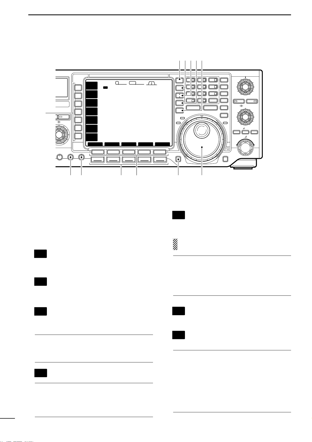
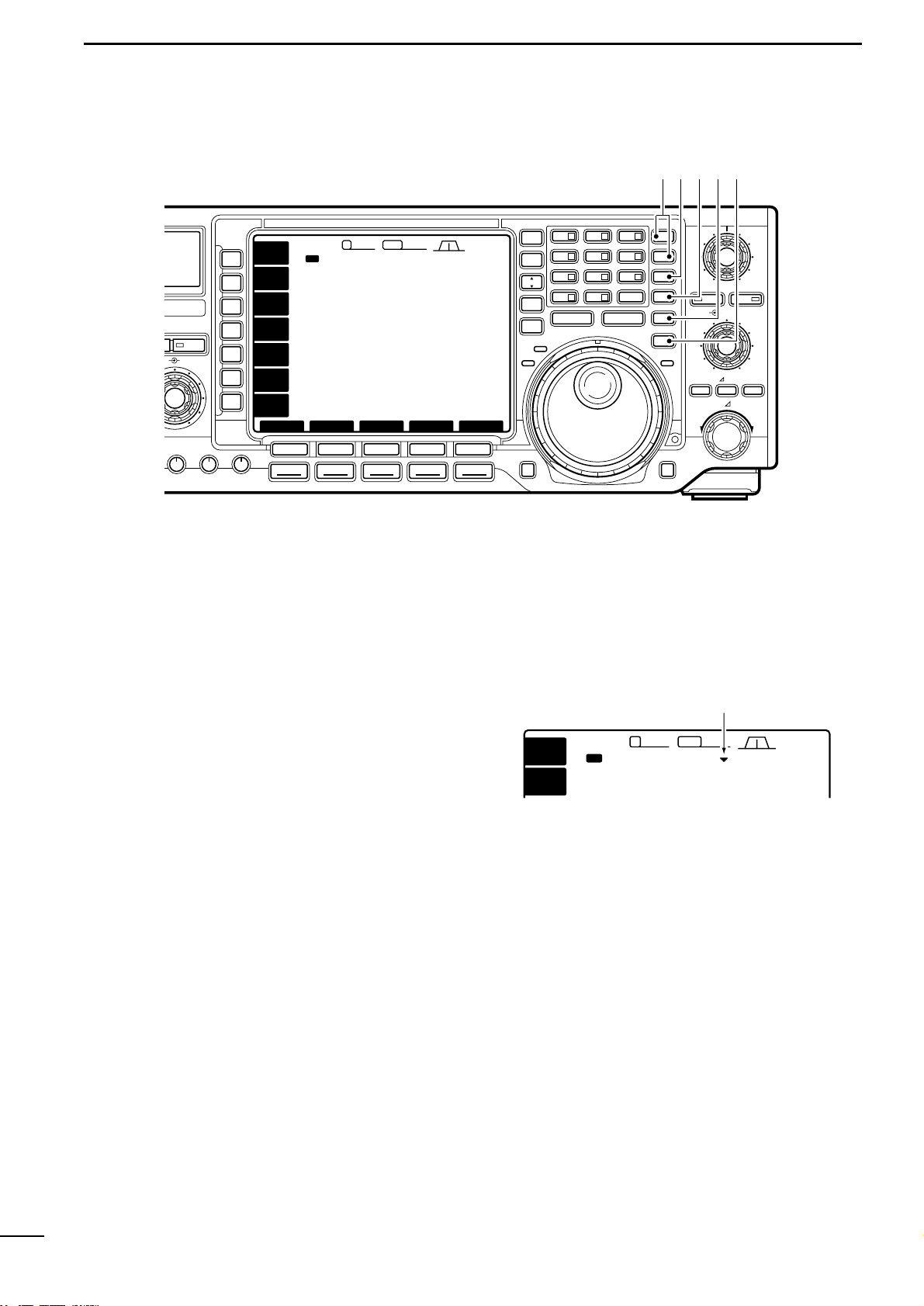
1 PANEL DESCRIPTION ......... 1–12
■Front panel ...................................... 1
■Microphone (HM-36) .......................8
■LCDdisplay ....................................9
■Screenmenu arrangement ........... 10
■Rearpanel .................................... 11
2 INSTALLATION AND
CONNECTIONS .................. 13–20
■Unpacking ....................................13
■Selecting alocation .......................13
■Grounding..................................... 13
■Antenna ........................................13
■Requiredconnections ................... 14
■Advancedconnections .................15
■Powersupplyconnections ............ 16
■Linearamplifier connections .........17
■External antenna selector or
antennatuner connections ...........18
■FSKand AFSK(SSTV)
connections ..................................19
■Remotejack(CI-V) information .....20
3 FREQUENCY SETTING ..... 21–24
■Whenfirst applyingpower
(CPUresetting) ............................. 21
■Initialsettings ................................ 21
■VFOdescription ............................22
■Frequency setting with the
tuningdial ..................................... 23
■Directfrequency entry with
thekeypad ....................................23
■Advancedtuningfunctions ............ 24
4
RECEIVE AND TRANSMIT
... 25–40
■Modeselection ............................. 25
■Twin PBToperation .......................25
■Autonotchfunction ....................... 26
■Noise reduction ............................. 26
■Noiseblanker ................................26
■APFfunction ................................. 27
■CWreverse mode .........................27
■RTTYreversemode ...................... 27
■CWpitch control ...........................27
■Filterselection .............................. 28
■RITand ∂TX .................................29
■Dualwatchoperation .....................30
■Splitfrequency operation ..............31
■Quicksplitfunction ........................ 32
■Monitorfunction ............................ 33
■VOXfunction ................................. 33
■Meterfunction ............................... 34
■Speech compressor ...................... 34
■SWRreading ................................ 34
■ElectronicCW keyer .....................35
■Memory keyer ............................... 36
■Spectrum scopescreen ................ 37
■Bandmemory
(forautomaticantenna selection)
....37
■Repeateroperation ....................... 38
■Diallockfunction ........................... 38
■Antennatuner operation ...............39
■
Optionalexternal tuneroperation
....40
5 MEMORY OPERATION ...... 41–46
■Memory channels ......................... 41
■Memory channel selection ............ 41
■Memory channel screen ............... 42
■Memory channel programming ..... 43
■Frequency transferring .................. 44
■Memory names .............................45
■Memory clearing ........................... 45
■Memopads ................................... 46
6 SCANS ................................ 47–50
■Scantypes .................................... 47
■Preparation ...................................47
■Programmedscanoperation .........48
■∂Fscan operation ........................48
■Fineprogrammedscan/
fine∂F scan .................................. 49
■Memory scan operation ................ 49
■Selectmemory scanoperation ..... 50
■Settingselect memory channels ... 50
7 CLOCK AND TIMERS ........ 51–52
■Settingthe currenttime ................. 51
■Settingpower-ontime ................... 51
■Settingpower-offperiod ................ 52
■Timeroperation ............................ 52
8 SET MODE .......................... 53–60
■Setmode description .................... 53
■Level setmode ..............................54
■Displaysetmode .......................... 54
■Timerset mode .............................55
■Miscellaneous(others) setmode .. 55
9
OPTION INSTALLATIONS
.... 61–62
■Openingthe transceiver’s case .....61
■UT-102VOICESYNTHESIZER
UNIT ..............................................61
■Optional IFfilters ........................... 62
■CR-502HIGH STABILITY
CRYSTALUNIT ............................... 62
10 MAINTENANCE .................. 63–65
■Troubleshooting ............................63
■Fusereplacement ......................... 64
■Clockbackup battery
replacement.................................. 64
■Tuning dialbrakeadjustment ........ 65
■Frequency calibration
(approximate)................................65
11 INTERNAL VIEWS .................... 66
12 SPECIFICATIONS .................... 67
13 OPTIONS .................................. 68

1
1PANEL DESCRIPTION
■Front panel
TIMER
POWER
TRANSMIT
PHONES
ELEC-KEY
MIC
TUNER MONITOR NB NR
AF BAL NRRF/SQL
MIC GAIN RF POWER COMP KEY SPEED BK-IN DELAY
SPo 010
1
11.5 23
59+20 +40 +60dB
25 50 100 %
∞
SWR
ALC
F-1
SSB
F-2 F-3 F-4 F-5
CW RTTY AM FM
HF/50MHz TRANSCEIVER i756
1ß
VFOVFO
14.195.000
VFOVFO
USBUSB
USB
14.100.0014.100.00
14.205.00014.205.000
USBUSB
USB
14.100.0014.100.00
5656
ß
TXTX
FILTER SCANMEMORY SET
VOXVOX
OFFOFF
COMPCOMP
OFFOFF
SCOPE
ANTANT
1
METERMETER
PoPo
P.AMPP.AMP
OFFOFF
ATTATT
OFFOFF
AGCAGC
MIDMID
2.42.492.82.8455455
12:3412:34
q
w
e
r
t
!3!4!5!6!7
y i !0!1 !2ou
qPOWER SWITCH [POWER/TIMER]
•Push momentarily to turn power ON.
- Turn the optional DC power supply ON in advance.
•Push momentarily to toggle the timer function ON
and OFF. (p. 52)
- The power switch lights while the timer function is ON.
•Push for 2 sec. to turn power OFF.
wTRANSMIT SWITCH [TRANSMIT]
Selects transmitting or receiving.
- The [TX] indicator lights red while transmitting and the
[RX] indicator lights green when the squelch is open.
eHEADPHONE JACK [PHONES]
Accepts headphones.
- When headphones are connected, the internal speaker
or connected external speaker does not function.
rELECTRONIC KEYER JACK [ELEC-KEY] (p. 35)
Accepts a paddle to activate the internal electronic
keyer for CW operation.
- Selection between the internal electronic keyer, bug-key
and straight key operation can be made in keyer set
mode. (p. 35)
- A straight key jack is separately available on the rear
panel. See [KEY] on p. 11.
- Keyer polarity (dot and dash) can be reversed in keyer
set mode. (p. 35)
- 4-channel memory keyer is available for your conve-
nience. (p. 36)
tMICROPHONE CONNECTOR [MIC]
Accepts the supplied or optional microphone.
- See p. 68 for appropriate microphones.
- See p. 8 for microphone connector information.
yAF CONTROL [AF] (inner control)
Varies the audio output level from the speaker.
uMIC GAIN CONTROL [MIC GAIN]
Adjusts microphone input gain.
✔
How to set the microphone gain.
Set the [MIC] control so that the ALC meter sometimes
swings during normal voice transmission in SSB mode.
IncreasesDecreases
Recommended level for
an Icom microphone
MIC GAIN
AF RF/SQL
No audio output Max. audio output
Decreases Increases
(dot)
(com)
(dash)

2
1
PANEL DESCRIPTION
iRF GAIN CONTROL/SQUELCH CONTROL
[RF/SQL] (outer control)
Adjusts the RF gain and squelch threshold level.
The squelch removes noise output from the speaker
(closed condition) when no signal is received.
- The squelch is particularly effective for FM. It is also
available for other modes.
- The control can be set as the RF gain control only
(squelch is fixed open) or squelch control (RF gain is
fixed at maximum) in set mode as follows. (p. 56)
- 11 to 12 o’clock position is recommended for any set-
ting of the [RF/SQL] control.
•When setting as RF gain/squelch control
oRF POWER CONTROL [RF POWER]
Continuously varies the RF output power from min-
imum (2 W*) to maximum (100 W*).
*AM mode: 1 W to 40 W
!0 BALANCE CONTROL [BAL] (inner control; p. 30)
Adjusts the audio output balance between main and
sub readout frequencies while in dualwatch.
!1 COMPRESSION LEVEL CONTROL [COMP]
(p. 34)
Adjusts the speech compression level in SSB.
!2 NOISE REDUCTION LEVEL CONTROL [NR]
(outer control; p. 26)
Adjusts the noise reduction level when the noise re-
duction is in use. Set for maximum readability.
!3 NOISE REDUCTION SWITCH [NR] (p. 26)
Toggles the noise reduction ON and OFF. Functions
in SSB, CW and RTTY modes.
!4 NOISE BLANKER SWITCH [NB] (p. 26)
Toggles the noise blanker ON and OFF. The noise
blanker reduces pulse-type noise such as that gen-
erated by automobile ignition systems. This function
cannot be used for FM, or non-pulse-type noise.
!5 S/RF METER (p. 34)
Shows the signal strength while receiving. Shows
the relative output power, SWR or ALC levels while
transmitting.
!6 MONITOR SWITCH [MONITOR] (p. 33)
Monitors your transmitted IF signal.
- The CW sidetone functions when [MONITOR] is OFF in
CW mode.
!7 ANTENNA TUNER SWITCH [TUNER] (p. 39)
•Turns the antenna tuner ON and OFF (bypass)
when pushed momentarily.
•Starts to tune the antenna manually when pushed
for 2 sec.
- When the tuner cannot tune the antenna, the tuning
circuit is bypassed automatically after 20 sec.
Noise blanker OFF Noise blanker ON
NB NB
Noise reduction OFF Noise reduction ON
NR NR
BAL NR
Decreases
OFF
Increases
Compression
level decreases Compression
level increases
COMP
BAL NR
Increases main
readout gain Increases sub
readout gain
IncreasesDecreases
RF POWER
Recommended level
Minimum RF gain
Adjustable
range
RF gain
adjustable
range
Maximum
RF gain
Maximum
RF gain
Squelch is
open. S-meter
squelch
S-meter squelch
threshold
Noise squelch
threshold (FM mode)
Shallow Deep
Squelch is
open.
S-meter
squelch
Noise squelch (FM mode)
•When setting as RF gain control
(Squelch is fixed open.)
•When setting as squelch control
(RF gain is fixed at maximum.)

NB NR
BAL NR
COMP KEY SPEED BK-IN DELAY
APF
APF
LOCKTX
RX
AUTO NOTCH
TWIN PBT
CW PITCH
F-1
SSB
F-2 F-3 F-4 F-5 SPEECH LOCK
RIT/ TX
TXRIT CLEAR
CW RTTY AM FM
SPLIT
MP-W MP-R
DUAL
WATCH
VFO/
MEMO
MAIN/
SUB
CHANGE
1.8 13.5 273
10 414 518 6
21 724.5 828 9
GENE
・ 50 0F-INPENT
▲
▼
MW
M-CL
TS
XFC
i756
1ß
VFOVFO
14.195.000
VFOVFO
USBUSB
USB
14.100.0014.100.00
14.205.00014.205.000
USBUSB
USB
14.100.0014.100.00
5656
ß
TXTX
FILTER SCANMEMORY SET
VOXVOX
OFFOFF
COMPCOMP
OFFOFF
SCOPE
ANTANT
1
METERMETER
PoPo
P.AMPP.AMP
OFFOFF
ATTATT
OFFOFF
AGCAGC
MIDMID
2.42.492.82.8455455
12:3412:34
!8
@5@6@7@8@9
@1@0!9 @2 @3 @4
!8 MULTI-FUNCTION SWITCHES
•Push to select the functions indicated in the LCD
display to the right of these switches.
- Functions vary depending on the operating condition.
•Push to input a character for memory keyer pro-
gramming or memory name. (pgs. 36, 45)
•Toggles the antenna connector selection
between ANT1/R and ANT2/R when
pushed. (p. 37)
•Toggles the receive antenna ON and OFF
when pushed for 2 sec.
•Selects RF power (Po), SWR or ALC me-
tering during transmit. (p. 34)
•Selects one of 2 receive RF preamps or
bypasses them.
- “P.AMP1”activates 10 dB preamp for HF all
bands.
- “P.AMP2”activates 16 dB high-gain preamp
for 21 MHz band and above.
✔
What is the preamp?
The preamp amplifies received signals in the front end cir-
cuit to improve the S/N ratio and sensitivity. Select
“P.AMP1”or “P.AMP2”when receiving weak signals.
•Selects 6 dB, 12 dB or 18 dB attenuator,
or bypasses them.
✔
What is the attenuator?
The attenuator prevents a desired signal from distorting
when very strong signals are near the desired frequency
or when very strong electric fields, such as from a broad-
casting station, are near your location.
•Activates or selects fast, middle or slow
AGC time constant when pushed.
- The setting becomes “fast”in FM mode re-
gardless of this setting.
•Deactivates the AGC circuit when pushed
for 2 sec.
NOTE: While “AGC OFF”is selected, the
S-meter does not function.
✔
What is the AGC?
The AGC controls receiver gain to produce a constant
audio output level even when the received signal strength
is varied by fading, etc. Select “FAST”for tuning and se-
lect “MID”or “SLOW”depending on the receiving condi-
tion.
•Turns the VOX function ON and OFF when
pushed in non-CW modes. (p. 33)
•Enters the VOX set mode when pushed for
2 sec. in non-CW modes. (p. 33)
•Selects semi break-in, full break-in opera-
tion, or turns the break-in operation OFF
when pushed in CW mode.
✔
What is the VOX function?
The VOX function (voice operated transmission) starts
transmission without pushing the transmit switch or PTT
switch when you speak into the microphone; then, auto-
matically returns to receive when you stop speaking.
✔
What is the break-in function?
The break-in function toggles transmit and receive with
CW keying. Full break-in (QSK) can monitor the receive
signal during keying.
VOXVOX
OFFOFF
BK-INBK-IN
OFFOFF
AGCAGC
MIDMID
ATTATT
OFFOFF
P.AMPP.AMP
OFFOFF
METERMETER
PoPo
ANTANT
1
3
1PANEL DESCRIPTION

•Turns the speech compressor ON and
OFF in SSB and AM modes. (p. 34)
•Enters memory keyer set mode in CW
mode. (pgs. 35, 36)
•Turns the 1⁄4function ON and OFF in
RTTY mode. (p. 24)
- 1⁄4function sets dial rotation to 1⁄4of normal for
fine tuning.
✔
What is the speech compressor?
The speech compressor compresses the transmitter
audio input to increase the average audio output level.
Therefore, talk power is increased. This function is effec-
tive for long distance communication or when propaga-
tion conditions are poor.
!9 ELECTRONIC CW KEYER SPEED CONTROL
[KEY SPEED] (p. 35)
Adjusts the internal electronic CW keyer’s speed.
- 7 wpm (min.) to 56 wpm (max.) can be set.
@0 SEMI BREAK-IN DELAY CONTROL
[BK-IN DELAY]
Adjusts the transmit-to-receive switching delay time
for CW semi break-in operation.
@1 MODE SWITCHES
Selects the desired mode. (p. 25)
- Announces the selected mode when an optional UT-102
is installed. (pgs. 59, 61)
•Selects SSB and SSB narrow (USB-N,
LSB-N) mode alternately.
•Toggles USB and LSB mode when pushed
for 2 sec.
•Selects CW and CW narrow (CW-N) mode
alternately.
•Toggles CW and CW-R (CW reverse)
mode when pushed for 2 sec.
•Selects RTTY and RTTY narrow (RTTY-N)
mode alternately.
•Toggles RTTY and RTTY-R (RTTY re-
verse) mode when pushed for 2 sec.
•Selects AM and AM narrow (AM-N) mode
alternately.
•Selects FM and FM narrow (FM-N) mode
alternately.
•Toggles the subaudible tone encoder ON
and OFF in FM mode when pushed for 2
sec. (pgs. 38, 57)
@2 LCD FUNCTION SWITCHES [F-1]–[F-5]
Push to select the function indicated in the LCD dis-
play above these switches.
- Functions vary depending on the operating condition.
@3 SPEECH SWITCH [SPEECH] (pgs. 59, 61)
Announces the selected readout frequency when an
optional UT-102 is installed.
@4 TUNING DIAL (p. 23)
Changes the displayed frequency, selects set mode
items, etc.
@5 MAIN/SUB SWITCH [MAIN/SUB]
Selects the main or sub readout for access.
- The sub readout frequency is displayed in outline and
functions only during split operation or dualwatch.
@6 VFO/MEMORY SWITCH [VFO/MEMO]
•Toggles the selected readout operating mode be-
tween the VFO mode and memory mode when
pushed. (pgs. 22, 41)
•Transfers the memory contents to VFO when
pushed for 2 sec. (p. 44)
@7 MAIN/SUB CHANGE SWITCH [CHANGE]
•Toggles the frequency and selected memory chan-
nel between main and sub readouts when pushed.
- Toggles between transmit frequency and receive fre-
quency when the split frequency function is ON. (p. 31)
•Equalizes the sub readout frequency to the main
readout frequency when pushed for 2 sec.
@8 DUALWATCH SWITCH [DUALWATCH] (p. 30)
•Turns the dualwatch function ON and OFF when
pushed.
•Turns the dualwatch function ON and equalizes the
sub readout frequency to the main readout when
pushed for 2 sec. (Quick dualwatch function)
- The quick dualwatch function can be turned OFF using
set mode. (p. 56)
@9 SPLIT SWITCH [SPLIT] (p. 31)
•Turns the split function ON and OFF when pushed.
•Turns the split function ON, equalizes the sub
readout frequency to the main readout and sets
the sub readout for frequency input when pushed
for 2 sec. in non-FM modes. (Quick split function)
- The offset frequency is shifted from the main readout
frequency in FM mode. (pgs. 38, 57)
•Turns the split function ON and shifts the sub read-
out frequency after inputting an offset (±1 MHz in 1
kHz steps).
FM
AM
RTTY
CW
SSB
BK-IN DELAY
Short delay for
high speed keying Long delay for
slow speed keying
Slow Fast
KEY SPEED
KEYERKEYER
1/41/4
OFFOFF
COMPCOMP
OFFOFF
4
1
PANEL DESCRIPTION

5
1PANEL DESCRIPTION
#0 LOCK SWITCH [LOCK] (p. 38)
Turns the dial lock function ON and OFF.
#1 RIT/∂∂TX CONTROL [RIT/∂∂TX](p. 29)
Shifts the receive and/or transmit frequency without
changing the transmit and/or receive frequency
while the RIT and/or ∂TX functions are ON.
- Rotate the control clockwise to increase the frequency,
or rotate the control counterclockwise to decrease the
frequency.
- The shift frequency range is ±9.999 kHz in 1 Hz steps
(or ±9.99 kHz in 10 Hz steps).
#2 RIT SWITCH [RIT] (p. 29)
•Turns the RIT function ON and OFF when pushed.
- Use the [RIT/∂TX] control to vary the RIT frequency.
•Adds the RIT shift frequency to the operating fre-
quency when pushed for 2 sec.
✔
What is the RIT function?
The RIT (Receiver Incremental Tuning) shifts the receive
frequency without shifting the transmit frequency.
This is useful for fine tuning stations calling you on an off-
frequency or when you prefer to listen to slightly different-
sounding voice characteristics, etc.
#3 ∂∂TX SWITCH [∂∂TX] (p. 29)
•Turns the ∂TX function ON and OFF when
pushed.
- Use the [RIT/∂TX] control to vary the ∂TX frequency.
•Adds the ∂TX shift frequency to the operating fre-
quency when pushed for 2 sec.
✔
What is the
∂∂
TX function?
The ∂TX shifts the transmit frequency without shifting the
receive frequency. This is useful for simple split frequency
operation in CW, etc.
#4 CLEAR SWITCH [CLEAR] (p. 29)
Clears the RIT/∂TX shift frequency when pushed
for 2 sec.
#5 CW PITCH CONTROL [CW PITCH]
(outer control; p. 27)
Shifts the received CW audio pitch and monitored
CW audio pitch without changing the operating fre-
quency.
Approx. 300 Hz Approx. 900 Hz
APF CW PITCH
Lower frequency Higher frequency
RIT/∂TX
Low shift High shift
NB NR
BAL NR
COMP KEY SPEED BK-IN DELAY
APF
APF
LOCKTX
RX
AUTO NOTCH
TWIN PBT
CW PITCH
F-1
SSB
F-2 F-3 F-4 F-5 SPEECH LOCK
RIT/ TX
TXRIT CLEAR
CW RTTY AM FM
SPLIT
MP-W MP-R
DUAL
WATCH
VFO/
MEMO
MAIN/
SUB
CHANGE
1.8 13.5 273
10 414 518 6
21 724.5 828 9
GENE
・ 50 0F-INPENT
▲
▼
MW
M-CL
TS
XFC
i756
1ß
VFOVFO
14.195.000
VFOVFO
USBUSB
USB
14.100.0014.100.00
14.205.00014.205.000
USBUSB
USB
14.100.0014.100.00
5656
ß
TXTX
FILTER SCANMEMORY SET
VOXVOX
OFFOFF
COMPCOMP
OFFOFF
SCOPE
ANTANT
1
METERMETER
PoPo
P.AMPP.AMP
OFFOFF
ATTATT
OFFOFF
AGCAGC
MIDMID
2.42.492.82.8455455
12:3412:34
$5$6 $4 $3 $1 $0 #9
#4
#6
#5
#3
#8
#7
#2
#1
#0
$2

6
1
PANEL DESCRIPTION
#6 AUDIO PEAK FILTER CONTROL [APF]
(inner control; p. 27)
Varies the peak frequency of the audio peak filter to
pick out a CW signal from interference while the
APF function is ON.
#7 AUDIO PEAK FILTER SWITCH [APF](p. 27)
•Turns the audio peak filter ON and OFF when
pushed.
- The APF indicator appears in the LCD.
- The audio peak filter functions in CW only.
•Toggles the bandwidth of the audio peak filter be-
tween 320, 160 or 80 Hz when pushed for 2 sec.
- Use the [APF] control to vary the peak frequency.
#8 AUTO NOTCH SWITCH [AUTO NOTCH](p. 26)
Turns the auto notch function ON and OFF.
- The auto notch functions in SSB only.
✔
What is the notch function?
The notch function eliminates unwanted CW or AM carrier
tones while preserving the desired signal’s audio re-
sponse. The filtering frequency is adjusted to effectively
eliminate unwanted tones via the DSP circuit.
#9 PASSBAND TUNING CONTROLS [TWIN PBT]
Adjust the receiver’s “passband width”of the 455
kHz and 9 kHz IF filters for the inner and outer con-
trols, respectively. (p. 25)
- Passband width and center frequency are displayed in
the LCD.
- Set to the center positions when not in use.
- Variable range depends on the filter selection. ±1.29
kHz in 15 Hz steps and ±258 kHz in 3 Hz steps are
available.
✔
What is the PBT control?
The PBT function electronically narrows the IF passband
width to reject interference. The PBT is especially effec-
tive in SSB operation and is not available in FM opera-
tion.
$0 LOCK INDICATOR [LOCK] (p. 38)
Lights when the dial lock function is activated.
$1 MEMO PAD-READ SWITCH [MP-R] (p. 46)
Each push calls up a frequency and operating mode
in a memo pad. The 5 (or 10) most recently pro-
grammed frequencies and operating modes can be
recalled, starting from the most recent.
- The memo pad capacity can be expanded from 5 to 10
in set mode for your convenience. (p. 59)
$2 KEYPAD
•Pushing a key selects the operating band.
- [GENE] selects the general coverage band.
•Pushing the same key 2 or 3 times calls up other
stacked frequencies in the band. (p. 23)
- Icom’s triple band stacking register memorizes 3 fre-
quencies in each band.
•After pushing [F-INP•ENT], enters a keyed fre-
quency or memory channel. Pushing [F-INP•ENT]
or [Y]/[Z] is necessary at the end. (pgs. 23, 41)
- e.g. to enter 14.195 MHz, push [F-INP•ENT] [1] [4] [•]
[1] [9] [5] [F-INP•ENT].
$3 MEMO PAD-WRITE SWITCH [MP-W] (p. 46)
Programs the selected readout frequency and op-
erating mode into a memo pad.
- The 5 most recent entries remain in memo pads.
- The transmit frequency is programmed when pushed to-
gether with [XFC].
- The memo pad capacity can be expanded from 5 to 10
in set mode for your convenience. (p. 59)
$4 RECEIVE INDICATOR [RX]
Lights green while receiving a signal and when the
squelch is open.
$5 TRANSMIT INDICATOR [TX]
Lights red while transmitting.
$6 LCD FUNCTION DISPLAY (See p. 9 for details.)
Shows the operating frequency, function switch
menus, spectrum screen, memory channel screen,
set mode settings, etc.
Low cut High cutCenter
TWIN PBT TWIN PBT TWIN PBT
–+
9 MHz PBT
455 kHz PBT
TWIN PBT
AUTO NOTCHAUTO NOTCH
Auto notch OFF Auto notch ON
APF function OFF APF function ON
APF APF
Approx. 300 Hz Approx. 900 Hz
APF CW PITCH
Lower frequency Higher frequency

7
1PANEL DESCRIPTION
$7 MEMORY UP/DOWN SWITCHES [YY]/[ZZ](p. 41)
•Select the memory channel number for the se-
lected readout.
- Memory channels can be selected both in VFO and
memory modes.
•Select the desired memory channel directly after
pushing [F-INP] and a memory channel number.
$8 MEMORY WRITE SWITCH [MW] (p. 43)
Stores the selected readout frequency and operat-
ing mode into the displayed memory channel when
pushed for 2 sec.
- This function is available both in VFO and memory
modes.
$9 MEMORY CLEAR SWITCH [M-CL] (p. 45)
Clears the selected readout memory channel con-
tents when pushed for 2 sec. in memory mode.
- The channel becomes a blank channel.
- This switch does not function in VFO mode.
%0 QUICK TUNING SWITCH [TS] (p. 24)
•Turns the quick tuning step ON and OFF.
- While the quick tuning indicator is displayed, the fre-
quency can be changed in programmed kHz steps.
- 1, 5, 9 and 10 kHz quick tuning steps are available.
•While the quick tuning step is OFF, turns the 1 Hz
step ON and OFF when pushed for 2 sec.
- 1 Hz indications appear in both readouts and the fre-
quency can be changed in 1 Hz steps.
•While the quick tuning step is ON, enters the quick
tuning step set mode when pushed for 2 sec.
%1 TRANSMIT FREQUENCY CHECK SWITCH
[XFC]
Monitors the transmit frequency when pushed and
held when the split frequency function is ON.
- While pushing this switch, the transmit frequency can be
changed with the tuning dial, keypad, memo pad or the
[Y]/[Z] switches.
- When the split lock function is turned ON, pushing [XFC]
cancels the dial lock function. (p. 57)
14.100.00
VFOVFO
USBUSB
USBUSB
14.205.0014.205.00
TXTX
1
ANTANT
1
METERMETER
PoPo
2.49 2.8455
12:34
Quick tuning indicator
NB NR
BAL NR
COMP KEY SPEED BK-IN DELAY
APF
APF
LOCKTX
RX
AUTO NOTCH
TWIN PBT
CW PITCH
F-1
SSB
F-2 F-3 F-4 F-5 SPEECH LOCK
RIT/ TX
TXRIT CLEAR
CW RTTY AM FM
SPLIT
MP-W MP-R
DUAL
WATCH
VFO/
MEMO
MAIN/
SUB
CHANGE
1.8 13.5 273
10 414 518 6
21 724.5 828 9
GENE
・ 50 0F-INPENT
▲
▼
MW
M-CL
TS
XFC
i756
1ß
VFOVFO
14.195.000
VFOVFO
USBUSB
USB
14.100.0014.100.00
14.205.00014.205.000
USBUSB
USB
14.100.0014.100.00
5656
ß
TXTX
FILTER SCANMEMORY SET
VOXVOX
OFFOFF
COMPCOMP
OFFOFF
SCOPE
ANTANT
1
METERMETER
PoPo
P.AMPP.AMP
OFFOFF
ATTATT
OFFOFF
AGCAGC
MIDMID
2.42.492.82.8455455
12:3412:34
$7 $8 $9 %0 %1

•MICROPHONE CONNECTOR
(Front panel view)
CAUTION: DO NOT short pin 2 to ground as this
can damage the internal 8 V regulator.
yGND (PTT ground)
tPTT
rMain readout squelch switch
qMicrophone input
w+8 V DC output
eFrequency up/down
uGND
(Microphone ground)
iMain readout AF output
(varies with [AF]/[BAL])
8
1
PANEL DESCRIPTION
■Microphone (HM-36)
qUP/DOWN SWITCHES [UP]/[DN]
Change the selected readout frequency or memory
channel.
- Continuous pushing changes the frequency or memory
channel number continuously.
- While pushing [XFC], the transmit readout frequency
can be controlled while in spilt frequency operation.
- The [UP]/[DN] switch can simulate a key paddle. Preset
in the keyer set mode. (p. 35)
wPTT SWITCH
Push and hold to transmit; release to receive.
q
w
+
+
q
w
ert
y
u
i
4700p
4700p
10µ
0.33µ
MICROPHONE
MIC
ELEMENT
2k
470
DOWN UP
PTT RECEIVE
TRANSMIT
MICROPHONE CABLE MICROPHONE PLUG
•HM-36 SCHEMATIC DIAGRAM
PIN NO. FUNCTION DESCRIPTION
w+8V DC output Max. 10 mA
eFrequencyup Ground
Frequencydown Groundthrough470Ω
rSquelchopen “LOW”level
Squelchclosed “HIGH”level

9
1PANEL DESCRIPTION
1ß
VFO
14.195.000
VFO
USB
USBUSB
14.100.00
14.205.00014.205.000
USB
USBUSB
14.100.00
5656
ß
MARKER
MARKER HOLD
HOLD
MAX-H
MAX-H
EXIT
EXIT
ANT
1
METER
Po
P.AMP
OFF
ATT
OFF
AGC
MID
VOX
OFF
COMP
OFF
SPANSPAN
TX
2.42.492.82.8455455
12:3412:34
Grid
2.5
10dB
-12.5 SPECTRUMSCOPE+12.5
320320APFAPF
r
t
i
i
!5 !3!4 !2 !1 !0 o
y
u
u
q
w
e
w
■LCD display
qTX INDICATOR
Indicates the frequency readout for transmit.
wVFO/MEMORY CHANNEL INDICATOR
(pgs. 22, 41)
Indicates the VFO mode or selected memory chan-
nel number.
eSELECT MEMORY CHANNEL INDICATOR
(p. 50)
Indicates the displayed memory channel is set as a
select memory channel.
rMULTI-FUNCTION SWITCH GUIDE
Indicates the function of the multi-function switches.
tLCD FUNCTION SWITCH GUIDE
Indicates the function of the LCD function switches
([F-1] –[F-5]).
yMULTI-FUNCTION SCREEN (p. 10)
Shows the screens for the spectrum scope, IF filter
selection, memory channel, scan or set modes.
uMEMORY CHANNEL READOUTS (p. 41)
•Show the selected memory channel contents in
VFO mode.
•Show the VFO contents in memory mode.
iFREQUENCY READOUTS (p. 23)
Show the operating frequency.
- Outline characters are used for non-accessing readout.
oCLOCK READOUT (p. 51)
Shows the current time.
!0 TWIN PBT INDICATOR (p. 25)
Graphically displays the passband width for twin
PBT operation and center frequency for IF shift op-
eration.
!1 QUICK TUNING INDICATOR (p. 24)
Appears when the quick tuning step function is in
use.
!2 455 kHz IF FILTER INDICATOR (p. 28)
Shows the 455 kHz IF filter selection using pass-
band width.
!3 9 MHz IF FILTER INDICATOR (p. 28)
Shows the 9 MHz IF filter selection using passband
width.
!4 MODE INDICATOR (p. 25)
Shows the selected mode.
!5 APF FREQUENCY INDICATOR (p. 27)
Appears when the audio peak filter is turned ON
and shows the boost frequency width of the audio
peak filter.

10
1
PANEL DESCRIPTION
80%
95%
F-1
F-1
F-2 F-3 F-4 F-5
[15 ]
[]
[NONE ]
[FILTER SELECTION][FILTER SELECTION]
9MHz9MHz 455 Hz455 HzDEFDEFEXITEXIT
AGCAGC
MIDMID
VOXVOX
OFFOFF
COMPCOMP
OFFOFF
SSB
2.4K
[15 ]
[9 ]
[]
[NONE ]
2.8K
98--.---.---------
99--.---.---------
P10.500.00LSBSCANEDGE
P229.999.99USBSCANEDGE
1--.---.---------˘
4--.---.---------
5--.---.---------
2--.---.---------
3--.---.---------
[MEMORY][MEMORY]
SETSETNAMENAMESELECTSELECT EXITEXIT
AGCAGC
MIDMID
VOXVOX
OFFOFF
COMPCOMP
OFFOFF
ROLLROLL
ProgrammedP1:0.500.00MHz
ScanedgesP2:29.999.99MHz
∂FSpan:±10 Hz
[SCAN][SCAN]
∂F ∂FSPANFSPANFINEFINE EXITEXIT
AGCAGC
MIDMID
VOXVOX
OFFOFF
COMPCOMP
OFFOFF
PROGPROG
LEVEL
DISPLAY
TIME&TIMER
OTHERS
[SET[SETMODE]MODE]
DISPDISP OTHERSOTHERSTIMETIME EXITEXIT
AGCAGC
MIDMID
VOXVOX
OFFOFF
COMPCOMP
OFFOFF
LEVELLEVEL
1ß
VFOVFO
14.195.000
VFOVFO
USBUSB
USB
14.100.0014.100.00
14.205.00014.205.000
USBUSB
USB
14.100.0014.100.00
5656
ß
FILTER SCANMEMORY SET
ANTANT
1
METERMETER
PoPo
P.AMPP.AMP
OFFOFF
ATTATT
OFFOFF
AGCAGC
MIDMID
VOXVOX
OFFOFF
COMPCOMP
OFFOFF
SCOPE
TXTX
2.42.492.82.8455455
12:3412:34
1ß
VFOVFO
14.195.000
VFOVFO
USBUSB
USBUSB
14.100.0014.100.00
14.205.00014.205.000
USBUSB
USBUSB
14.100.0014.100.00
5656
ß
MARKERMARKER HOLDHOLDMAX-HMAX-HEXITEXIT
ANTANT
1
METERMETER
PoPo
P.AMPP.AMP
OFFOFF
ATTATT
OFFOFF
AGCAGC
MIDMID
VOXVOX
OFFOFF
COMPCOMP
OFFOFF
SPANSPAN
TX
2.42.492.82.8455455
12:3412:34
Grid
2.5
10dB
-12.5 SPECTRUMSCOPE+12.5
F-2
F-3
F-4
F-5
•Spectrum scope screen (p. 37)
•Start up screen •Filter selection screen (p. 28)
•Memory channel screen (p. 42)
•Scan screen (p. 47)
•Set mode screen (p. 53)
■Screen menu arrangement
The following screens can be selected from the start
up screen. Choose the desired screen using the fol-
lowing chart.
Pushing [(F-5)EXIT] one or more times returns to the
start up screen. See p. 53 for set mode arrangement.

qRECEIVE ANTENNA CONNECTOR [RX ANT]
(p. 15)
Connects a 50 Ωgeneral coverage antenna with an
RCA connector.
wTUNER CONTROL SOCKET [TUNER] (p. 15)
Accepts the control cable from an optional AH-3 HF
AUTOMATIC ANTENNA TUNER.
eACCESSORY SOCKET 1 [ACC(1)]
rACCESSORY SOCKET 2 [ACC(2)]
Enable connection to external equipment such as a
linear amplifier, an automatic antenna selector/
tuner, TNC for data communications, etc.
- See the page at right for socket information.
tSTRAIGHT KEY JACK [KEY] (p. 14)
Accepts a straight key or external electronic keyer
with 1⁄4inch standard plug.
- [ELEC-KEY] on the front panel can be used for a
straight key or external electronic keyer. Deactivate the
internal electronic keyer in keyer set mode. (p. 35)
NOTE: If you use an external electronic keyer,
make sure the voltage retained by the keyer is
less than 0.4 V when the key is ON.
yCI-V REMOTE CONTROL JACK [REMOTE]
(p. 20)
•Designed for use with a personal computer for re-
mote control of transceiver functions.
•Used for transceive operation with another Icom
CI-V transceiver or receiver.
uEXTERNAL SPEAKER JACK [EXT SP]
(pgs. 15, 68)
Accepts an 4–8 Ωspeaker.
iALC INPUT JACK [ALC] (p. 17)
Connects to the ALC output jack of a non-Icom lin-
ear amplifier.
oSEND CONTROL JACK [SEND] (p. 17)
Goes to ground while transmitting to control external
equipment such as a linear amplifier.
- Max. control level: 16 V DC/2 A
!0 DC POWER SOCKET [DC 13.8V] (p. 14)
Accepts 13.8 V DC through the supplied DC power
cable (OPC-025A).
11
1PANEL DESCRIPTION
■Rear panel
q o
!0
wertyui
!3 !2 !1
Rear panel
view +_
(+)
(_)

12
1
PANEL DESCRIPTION
!1 ANTENNA CONNECTOR 1 [ANT1]
!2 ANTENNA CONNECTOR 2 [ANT2] (pgs. 13, 14)
Accept a 50 Ωantenna with a PL-259 connector.
NOTE: When using an optional AH-3 HF AUTOMATIC
ANTENNA TUNER, connect it to the [ANT1] connector.
The internal antenna tuner activates for [ANT2] and
deactivates for [ANT1] when connecting the AH-3.
DACC SOCKETS
!3 GROUND TERMINAL [GND] (pgs. 13, 14)
Connect this terminal to a ground to prevent electri-
cal shocks, TVI, BCI and other problems.
ACC(1) PIN NO.
PIN NAME
DESCRIPTION SPECIFICATIONS
1RTTY Controls RTTY keying. “HIGH”level : More than 2.4 V
“LOW”level : Less than 0.6 V
Output current : Less than 2 mA
2GND Connects to ground. Connected in parallel with ACC(2) pin 2.
3SEND
Input/output pin.
Goes to ground when transmitting.
When grounded, transmits.
Ground level : –0.5 V to 0.8 V
Output current : Less than 20 mA
Input current (Tx) : Less than 200 mA
Connected in parallel with ACC(2) pin 3.
4MOD Modulator input.
Connects to a modulator. Input impedance : 10 kΩ
Input level : Approx. 100 mV rms
5AF AF detector output.
Fixed, regardless of [AF] position. Output impedance : 4.7 kΩ
Output level : 100 to 300 mV rms
6SQLS Squelch output.
Goes to ground when squelch
opens.
Squelch open : Less than 0.3 V/5 mA
Squelch closed : More than 6.0 V/100 µA
713.8 V 13.8 V output when power is ON. Output current : Max. 1 A
Connected in parallel with ACC(2) pin 7.
8ALC ALC voltage input. Control voltage : –4 to 0 V
Input impedance : More than 10 kΩ
Connected in parallel with ACC(2) pin 5.
Rear panel
view
1
2
3
45
67
8
ACC(2) PIN NO.
PIN NAME
DESCRIPTION SPECIFICATIONS
18 V Regulated 8 V output. Output voltage : 8 V ±0.3 V
Output current : Less than 10 mA
2GND Same as ACC(1) pin 2.
3SEND Same as ACC(1) pin 3.
4BAND Band voltage output.
(Varies with amateur band) Output voltage : 0 to 8.0 V
5ALC Same as ACC(1) pin 8.
6NC No connection.
713.8 V Same as ACC(1) pin 7.
Rear panel
view
1
2
3
45
67

■Unpacking
After unpacking, immediately report any damage to the
delivering carrier or dealer. Keep the shipping cartons.
For a description and a diagram of accessory equip-
ment included with the IC-756, see UNPACKING on
p. ii of this manual.
■Selecting a location
Select a location for the transceiver that allows ade-
quate air circulation, free from extreme heat, cold, or
vibrations, and away from TV sets, TV antenna ele-
ments, radios and other electro-magnetic sources.
■Grounding
To prevent electrical shock, television interference
(TVI), broadcast interference (BCI) and other prob-
lems, ground the transceiver through the GROUND ter-
minal on the rear panel.
For best results, connect a heavy gauge wire or strap
to a long earth-sunk copper rod. Make the distance be-
tween the GROUND terminal and ground as short as
possible.
RWARNING: NEVERconnect the [GND]
terminal to a gas or electric pipe, since the connec-
tion could cause an explosion or electric shock.
OPERATING ANGLE ADJUSTMENT
■Antenna
For radio communications, the antenna is of critical im-
portance, along with output power and sensitivity. Se-
lect antenna(s), such as a well-matched 50 Ωantenna,
and feedline. 1.5:1 of Voltage Standing Wave Ratio
(VSWR) is recommended for a desired band. Of
course, the transmission line should be a coaxial cable.
When using 1 antenna, use the [ANT1] connector.
CAUTION: Protect your transceiver from lightning by
using a lightning arrestor.
13
2INSTALLATION AND CONNECTIONS
PL-259 CONNECTOR INSTALLATION
30 mm ≈9⁄8in 10 mm ≈3⁄8in 1–2 mm ≈1⁄16 in
Antenna SWR
Each antenna is tuned for a specified frequency
range and SWR may be increased out-of-range.
When the SWR is higher than approx. 2.0:1, the
transceiver’s power drops to protect the final transis-
tor. In this case, an antenna tuner is useful to match
the transceiver and antenna. Low SWR allows full
power for transmitting even when using the antenna
tuner. The IC-756 has an SWR meter to monitor the
antenna SWR continuously.
30 mm
10 mm (soft solder)
10 mm
1–2 mm
solder solder
Soft
solder
Coupling ring
Slide the coupling ring
down. Strip the cable
jacket and soft solder.
Slide the connector
body on and solder it.
Screw the coupling
ring onto the
connector body.
Strip the cable as
shown at left. Soft
solder the center con-
ductor.
q
w
e
r
The rubber feet on the
bottom of the trans-
ceiver provide two op-
erating angles.

TIMER
POWER
TRANSMIT
PHONES
ELEC-KEY
MIC
TUNER MONITOR NB NR
MIC GAIN RF POWER COMP KEY SPEED BK-IN DELAY
AF RF/SQL BAL NR
APF
LOCKTX
RX
AUTO NOTCH
TWIN PBT
APF CW PITCH
SPo 010
1
11.5 23
59+20 +40 +60dB
25 50 100 %
∞
SWR
ALC
F-1
SSB
F-2 F-3 F-4 F-5 SPEECH LOCK
RIT/ TX
TXRIT CLEAR
CW RTTY AM FM
SPLIT
MP-W MP-R
DUAL
WATCH
VFO/
MEMO
MAIN/
SUB
CHANGE
1.8 13.5 273
10 414 518 6
21 724.5 828 9
GENE
・ 50 0F-INPENT
▲
▼
MW
M-CL
TS
XFC
HF/50MHz TRANSCEIVER
i756
CW KEY
A straight key can be used
when the internal electronic
keyer is turned OFF in keyer
set mode. (p. 35)
MICROPHONES (p. 68)
SM-20HM-36
GROUND (p. 13)
Use the heaviest gauge wire
or strap available and make
the connection as short as
possible.
Grounding prevents electrical
shocks, TVI and other
problems.
ANTENNA 1, 2 (p. 13)
[Example]: ANT1 for 1.8–18 MHz bands
ANT2 for 21–50 MHz bands
DC POWER SUPPLY
STRAIGHT KEY
PS-85
14
2
INSTALLATION AND CONNECTIONS
■Required connections
•Front panel
•Rear panel

15
2INSTALLATION AND CONNECTIONS
■Advanced connections
•Front panel
TIMER
POWER
TRANSMIT
PHONES
ELEC-KEY
MIC
TUNER MONITOR NB NR
MIC GAIN RF POWER COMP KEY SPEED BK-IN DELAY
AF RF/SQL BAL NR
APF
LOCKTX
RX
AUTO NOTCH
TWIN PBT
APF CW PITCH
SPo 010
1
11.5 23
59+20 +40 +60dB
25 50 100 %
∞
SWR
ALC
F-1
SSB
F-2 F-3 F-4 F-5 SPEECH LOCK
RIT/ TX
TXRIT CLEAR
CW RTTY AM FM
SPLIT
MP-W MP-R
DUAL
WATCH
VFO/
MEMO
MAIN/
SUB
CHANGE
1.8 13.5 273
10 414 518 6
21 724.5 828 9
GENE
・ 50 0F-INPENT
▲
▼
MW
M-CL
TS
XFC
HF/50MHz TRANSCEIVER
i756
HEADPHONES
MIC
The AFSK modulation signal
can be input from [MIC]. (p. 19)
ANTENNA 1, 2 (pgs. 17, 18)
Connects a linear amplifier,
antenna selector, etc.
EXTERNAL SPEAKER (p. 68)
ACC SOCKETS (p. 12)
RX ANTENNA
SP-20
AH-3 (p. 18)
AH-2b
[REMOTE] (pgs. 20, 60)
Used for computer control and transceive operation.
[RELAY], [ALC]
(p. 17)
Used for connecting a
non-Icom linear ampli-
fier.
When using the AH-3, it must
be connected to the [ANT1]
connector.
•Rear panel

16
2
INSTALLATION AND CONNECTIONS
■Power supply connections
Use an optional PS-85 DC POWER SUPPLY, etc. when
operating the transceiver with AC power. Refer to the
diagrams below.
CONNECTING AN ICOM DC POWER SUPPLY
to DC power socket
PS-85
AC outlet
AC cable
Transceiver
CONNECTING A NON-ICOM DC POWER SUPPLY
to DC power
socket
Non-Icom power supply
AC outlet
AC cable 20 A fuses
Supplied
DC power cable
13.8 V 20 A
Black
_Red
+
Transceiver
CONNECTING A VEHICLE BATTERY
12 V
battery Supplied
DC power cable
+red
-black
Crimp
Solder
Grommet
CAUTION: Before connecting the DC power cable,
check the following important items. Make sure:
•The [POWER] switch is OFF.
•Output voltage of the power source is 12–15 V when you
use a non-Icom power supply.
•DC power cable polarity is correct.
Red : positive +terminal
Black : negative _terminal
NEVER connect
to a 24 V battery.
NOTE: Use terminals for
the cable connections.

17
2INSTALLATION AND CONNECTIONS
■Linear amplifier connections
Transceiver
Ground
IC-4KL
Remote
controller
Coaxial cable (supplied with the IC-4KL)
ACC cable (supplied with the IC-4KL)
ACC
IC-4KL
Remote control cable
(supplied with the IC-4KL)
AC outlet (220–240 V)
To an
antenna
ANT1
ACC(2)
Use the [ANT1] connector when connecting a linear
amplifier.
NOTE: Turn OFF the transceiver’s antenna tuner while tuning the IC-4KL’s tuner.
Transceiver
Ground
Coaxial cable (supplied with the IC-2KL)
ACC cable (supplied with the IC-2KL)
IC-2KL
To the IC-2KLPS
OPC-118 (sold separately)
To an antenna
ANT
GND
ANT1
ACC(2)ACC(1)
CAUTION:
Set the transceiver output
power for 80 W max. with
the [RF POWER] control,
otherwise, a protection cir-
cuit will activate.
CONNECTING THE IC-4KL
CONNECTING THE IC-2KL
CONNECTING A NON-ICOM POWER AMPLIFIER
50 Ωcoaxial cable
NON-ICOM LINEAR
AMPLIFIER
To an
antenna
Transceiver
ANT1
RF OUTPUT
ALC SEND
RF INPUT
ALC
SEND
RWARNING:
Set the transceiver output power
and linear amplifier ALC output
level referring to the linear ampli-
fier instruction manual.
The ALC input level must be in the
range 0 V to –4 V, and the trans-
ceiver does not accept positive
voltage. Non-matched ALC and
RF power settings could cause a
fire or ruin the linear amplifier. NOTE: The specifications for the SEND relay are 16 V DC 2 A. If
this level is exceeded, a large external relay must be used.
Other manuals for IC-756
4
Table of contents
Other Icom Transceiver manuals