Icom IC-M510 User manual

INSTRUCTION MANUAL
This device complies with Part 15 of the FCC
Rules. Operation is subject to the condition that
this device does not cause harmful interference.
VHF MARINE TRANSCEIVER
|M510
TRIAL MODE - Click here for more information

i
Thank you for choosing this Icom product.
This product was designed and built with Icom’s state of the art technology and
craftsmanship. With proper care, this product should provide you with years of trouble-
free operation.
Icom is not responsible for the
destruction, damage to, or performance
of any Icom or non-Icom equipment, if the
malfunction is because of:
•
Force majeure, including, but not
OLPLWHGWR¿UHVHDUWKTXDNHVVWRUPV
ÀRRGVOLJKWQLQJRWKHUQDWXUDOGLVDVWHUV
disturbances, riots, war, or radioactive
contamination.
•
The use of Icom transceivers with any
equipment that is not manufactured or
approved by Icom.
■
Features
z
Fixed mount Class D DSC marine VHF
Transceiver
z
Integrated Wireless LAN for connection
with RS-M500 and CT-M500.
z
AIS information display*
.
*
An external AIS receiver or an external
NMEA sentence is required
z
New Sleek Design
z
Wide (nearly 180 degree) viewing angle
color TFT LCD with night mode.
z
6LPSOL¿HGQDYLJDWLRQIXQFWLRQ
z
Clear, Loud Audio
z
White light backlit keys for increased
visibility in low-light and dark conditions.
z
Integrated GPS receiver.
■
Important
READ ALL INSTRUCTIONS
carefully and
completely before using the transceiver.
SAVE THIS INSTRUCTION MANUAL
—
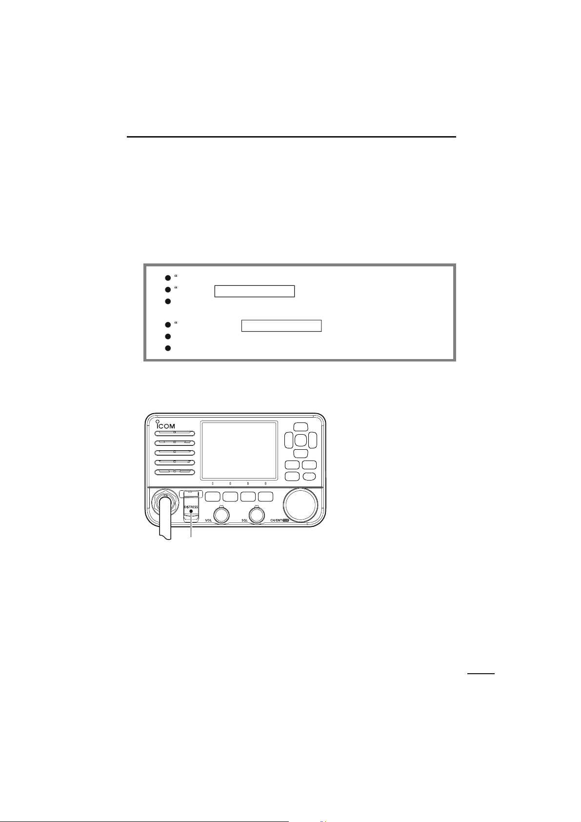
This instruction manual contains important
operating instructions for the IC-M510.
This instruction manual includes some
functions that are usable only when they
are preset by your dealer.
Ask your dealer for details.
■
([SOLFLW'H¿QLWLRQV
WORD
DEFINITION
R
WARNING!
3HUVRQDOLQMXU\¿UHKD]DUG
or electric shock may
occur.
CAUTION
Equipment damage may
occur.
NOTE
If disregarded,
inconvenience only. No risk
RISHUVRQDOLQMXU\¿UHRU
electric shock.
Icom, Icom Inc. and the Icom logo are
registered trademarks of Icom Incorporated
(Japan) in Japan, the United States, the
United Kingdom, Germany, France, Spain,
Russia, Australia, New Zealand, and/or
other countries.
AquaQuake is a trademark of Icom
Incorporated.
COMMANDMIC is a trademark of Icom
Incorporated.
NMEA 2000 is a trademark of the National
Maritime Electronics Association, Inc.
Android is a trademark of Google, LLC.
IOS is a trademark or registered trademark
of Cisco in the U.S. and other countries and
is used under license.
All other products or brands are registered
trademarks or trademarks of their
respective holders.
TRIAL MODE - Click here for more information

ii
1
7
4
10
15
18
2
8
13
5
11
16
3
9
14
6
12
17
■
In Case of Emergency
If your vessel requires assistance, contact other vessels and the Coast Guard by sending
a distress call on Channel 16 or transmit your Distress call using Digital Selective Calling
(DSC) on Channel 70.
D
Using Channel 16
1.
Push [16/C] to switch to Channel 16.
2.
While holding down [PTT], give the appropriate information as follows:
z
“
MAYDAY MAYDAY MAYDAY
.”
z
“
THIS IS
” (name of vessel).
z
Say your call sign or other indication of the vessel
(AND your 9 digit DSC ID, if you have one).
z
“
LOCATED AT
” (your position).
z
State the nature of the distress and assistance required.
z
Give any other information which might facilitate the rescue.
D
Using Digital Selective Calling
1.
Lift up the key cover, hold down [DISTRESS] for 3 seconds until the 3 short beeps
and then one long beep sound.
PWR
2.
Wait for an acknowledgment from another station.
3.
After the acknowledgment is received, Channel 16 is automatically selected.
4.
Hold down [PTT], then transmit the appropriate information as listed above.
Key cover
TRIAL MODE - Click here for more information

iii
W AR N IN G
Icom requires the radio operator to meet the FCC Requirements for Radio
Frequency Exposure. An omnidirectional antenna with gain not greater than
9 dBi must be mounted a minimum of 5 meters (measured from the lowest
point of the antenna) vertically above the main deck and all possible
personnel. This is the minimum safe separation distance estimated to meet
all RF exposure compliance requirements. This 5 meter distance is based
on the FCC Safe Maximum Permissible Exposure (MPE) distance of 3 meters added to
the height of an adult (2 meters) and is appropriate for all vessels.
For watercraft without suitable structures, the antenna must be mounted so as to maintain
a minimum of 1 meter vertically between the antenna, (measured from the lowest point
of the antenna), to the heads of all persons AND all persons must stay outside of the 3
meter MPE radius.
Do not transmit with radio and antenna when persons are within the MPE radius of
the antenna, unless such persons (such as driver or radio operator) are shielded from
DQWHQQD¿HOGE\DJURXQGHGPHWDOOLFEDUULHU7KH03(5DGLXVLVWKHPLQLPXPGLVWDQFH
from the antenna axis that person should maintain in order to avoid RF exposure higher
than the allowable MPE level set by FCC.
FAILURE TO OBSERVE THESE LIMITS MAY ALLOW THOSE WITHIN THE MPE
RADIUS TO EXPERIENCE RF RADIATION ABSORPTION WHICH EXCEEDS THE
FCC MAXIMUM PERMISSIBLE EXPOSURE (MPE) LIMIT.
IT IS THE RESPONSIBILITY OF THE RADIO OPERATOR TO ENSURE THAT THE
MAXIMUM PERMISSIBLE EXPOSURE LIMITS ARE OBSERVED AT ALL TIMES
DURING RADIO TRANSMISSION. THE RADIO OPERATOR IS TO ENSURE THAT
NO BYSTANDERS COME WITHIN THE RADIUS OF THE MAXIMUM PERMISSIBLE
EXPOSURE LIMITS.
Determining MPE Radius
THE MAXIMUM PERMISSIBLE EXPOSURE (MPE) RADIUS HAS BEEN ESTIMATED
TO BE A RADIUS OF ABOUT 3 M PER OET BULLETIN 65 OF THE FCC.
THIS ESTIMATE IS MADE ASSUMING THE MAXIMUM POWER OF THE RADIO AND
ANTENNAS WITH A MAXIMUM GAIN OF 9 dBi ARE USED FOR A SHIP MOUNTED
SYSTEM.
■
Radio Operation Warning
IC-M510 and CT-M500 RF Safety warning
An internal Wireless LAN module and an antenna are supplied with the IC-M510 and
CT-M500.
To comply with FCC/ISED RF Exposure for the installed Wireless LAN unit, the device
should be installed and operated with a minimum distance of 20 cm between the device
and all persons. No other transmitting antenna is permitted to be located within 20 cm of
the device.
TRIAL MODE - Click here for more information

iv
1
7
4
10
15
18
2
8
13
5
11
16
3
9
14
6
12
17
A V E R T I S S E M E N T
Icom exige que l’opérateur radio se conforme aux exigences de la FCC
en matière d’exposition aux radiofréquences. Une antenne
RPQLGLUHFWLRQQHOOHGRQWOHJDLQQHGpSDVVHSDVG%LGRLWrWUH¿[pHj
une distance minimale de 5 mètres (mesurée depuis le point le plus bas
de l’antenne) verticalement au-dessus du pont principal et de tout le
personnel qui peut s’y trouver. Il s’agit de la distance de sécurité
minimale prévue pour satisfaire aux exigences de conformité en matière d’exposition aux
RF. Cette distance de 5 mètres est établie en fonction de l’exposition maximale
DGPLVVLEOHVpFXULWDLUHGHPqWUHVpWDEOLHSDUOD)&&jODTXHOOHRQDMRXWHODKDXWHXUG¶XQ
adulte (2 mètres); cette distance convient pour tous les navires.
'DQVOHFDVGHVHPEDUFDWLRQVVDQVVWUXFWXUHFRQYHQDEOHO¶DQWHQQHGRLWrWUH¿[pHGH
IDoRQjPDLQWHQLUXQHGLVWDQFHPLQLPDOHGHPqWUHYHUWLFDOHPHQWHQWUHFHWWHDQWHQQH
(mesurée depuis son point le plus bas) et la tête de toute personne présente; toutes
OHVSHUVRQQHVSUpVHQWHVGRLYHQWVHWHQLUjO¶H[WpULHXUG¶XQUD\RQG¶H[SRVLWLRQPD[LPDOH
admissible de 3 mètres.
1HSDVpPHWWUHjO¶DLGHGHODUDGLRHWGHO¶DQWHQQHORUVTXHGHVSHUVRQQHVVHWURXYHQWj
O¶LQWpULHXUGXUD\RQG¶H[SRVLWLRQPD[LPDOHDGPLVVLEOHGHFHWWHDQWHQQHjPRLQVTXHFHV
personnes (comme le conducteur ou l’opérateur radio) ne soient protégées du champ
GHO¶DQWHQQHSDUXQpFUDQPpWDOOLTXHUHOLpjODPDVVH/HUD\RQG¶H[SRVLWLRQPD[LPDOH
DGPLVVLEOHpTXLYDXWjODGLVWDQFHPLQLPDOHTXHFHWWHSHUVRQQHGRLWPDLQWHQLUHQWUHHOOH
et l’axe de l’antenne pour éviter une exposition aux RF supérieure au niveau d’exposition
PD[LPDOHDGPLVVLEOH¿[pSDUOD)&&
LE NON-RESPECT DE CES LIMITES PEUT CAUSER, POUR LES PERSONNES
SITUÉES DANS LE RAYON D’EXPOSITION MAXIMALE ADMISSIBLE, UNE
ABSORPTION DE RAYONNEMENT DE RF SUPÉRIEURE À L’EXPOSITION
MAXIMALE ADMISSIBLE FIXÉE PAR LA FCC.
L’OPÉRATEUR RADIO EST RESPONSABLE D’ASSURER QUE LES LIMITES
D’EXPOSITION MAXIMALE ADMISSIBLE SOIENT RESPECTÉES EN TOUT TEMPS
PENDANT LA TRANSMISSION RADIO. L’OPÉRATEUR RADIO DOIT S’ASSURER
QU’AUCUNE PERSONNE PRÉSENTE NE SE SITUE À L’INTÉRIEUR DU RAYON
D’EXPOSITION MAXIMALE ADMISSIBLE.
Établir le rayon d’exposition maximale admissible
ON ESTIME QUE LE RAYON D’EXPOSITION MAXIMALE ADMISSIBLE EST
D’ENVIRON 3 M, TEL QUE STIPULÉ DANS LE BULLETIN OET 65 DE LA FCC.
CETTE DISTANCE ESTIMÉE TIENT COMPTE D’UN SYSTÈME INSTALLÉ SUR UN
NAVIRE UTILISANT LA PUISSANCE MAXIMALE DE LA RADIO ET DES ANTENNES
DONT LE GAIN MAXIMAL EST DE 9 dBi.
■
Avertissement Pour Les Opérateurs Radio
Avertissement de sécurité RF IC-M510 et CT-M500
8QPRGXOH/$1VDQV¿OLQWHUQHHWXQHDQWHQQHVRQWIRXUQLVDYHF
O¶,&0HWOH&70
3RXUVHFRQIRUPHUjO¶H[SRVLWLRQDX[5))&&,6('SRXUO¶XQLWp/$1VDQV¿OLQVWDOOpH
O¶DSSDUHLOGRLWrWUHLQVWDOOpHWXWLOLVpjXQHGLVWDQFHPLQLPDOHGHFPHQWUHO¶DSSDUHLOHW
WRXWHVOHVSHUVRQQHV$XFXQHDXWUHDQWHQQHG¶pPLVVLRQQ¶HVWDXWRULVpHjrWUHVLWXpHj
moins de 20 cm de l’appareil.
TRIAL MODE - Click here for more information

v
■
FCC Information
This equipment has been tested and found to comply with the limits for a Class B digital
device, pursuant to part 15 of the FCC Rules. These limits are designed to provide
reasonable protection against harmful interference in a residential installation. This
equipment generates, uses, and can radiate radio frequency energy and, if not installed
and used in accordance with the instructions, may cause harmful interference to radio
communications. However, there is no guarantee that interference will not occur in a
particular installation. If this equipment does cause harmful interference to radio or
WHOHYLVLRQUHFHSWLRQZKLFKFDQEHGHWHUPLQHGE\WXUQLQJWKHHT
XLSPHQWRႇDQGRQWKHXVHU
is encouraged to try to correct the interference by one or more of the following measures:
•
Reorient or relocate the receiving antenna.
•
Increase the separation between the equipment and receiver.
•
&RQQHFWWKHHTXLSPHQWLQWRDQRXWOHWRQDFLUFXLWGLႇHUHQWIURPWKDWWRZKLFKWKHUHFHLYHU
is connected.
•
Consult the dealer or an experienced radio/TV technician for help.
CAUTION
&KDQJHVRUPRGL¿FDWLRQVWRWKLVWUDQVFHLYHUQRWH[SUHVVO\DSSURYHGE\
Icom Inc., could void your authority to operate this transceiver under FCC regulations.
■
Information FCC
&HWDSSDUHLOHVWFRQIRUPHjODSDUWLHGHODUpJOHPHQWDWLRQ)&&6RQIRQFWLRQQHPHQW
HVWVRXPLVjODFRQGLWLRQTXHFHWDSSDUHLOQHSURYRTXHSDVG¶LQWHUIpUHQFHVQRFLYHV
&HWpTXLSHPHQWDpWpWHVWpHWUHFRQQXFRQIRUPHDX[OLPLWHV¿[pHVSRXUXQDSSDUHLO
QXPpULTXHGHFODVVH%FRQIRUPpPHQWjODSDUWLHGHODUpJOHPHQWDWLRQ)&&
&HVOLPLWHVRQWpWp¿[pHVD¿QG¶DVVXUHUXQHSURWHFWLRQUDLVRQQDEOHFRQWUHOHV
interférences nocives dans une installation résidentielle. Cet équipement génère,
utilise et peut émettre un rayonnement de fréquence radio. S’il n’a pas été installé
conformément aux instructions, il peut par ailleurs créer des interférences perturbant les
communications radio. Toutefois, il n’y a aucune garantie que les interférences ne se
produiront pas dans une installation particulière. Si cet équipement crée des interférences
perturbant la réception de la radio ou de la télévision, comme cela peut être déterminé
HQpWHLJQDQWHWHQDOOXPDQWO¶pTXLSHPHQWO¶XWLOLVDWHXUHVWLQYLWpjHVVD\HUGHFRUULJHU
l’interférence en prenant une ou plusieurs des mesures ci-après :
•
Réorienter ou changer de place l’antenne de réception.
•
Éloigner l’équipement et le récepteur.
•
Connecter l’équipement sur une prise sur un autre circuit que celui sur lequel le
récepteur est connecté.
•
)DLUHDSSHODXUHYHQGHXURXjXQWHFKQLFLHQUDGLR79H[SpULPHQWp
MISE EN GARDE:
7RXWFKDQJHPHQWRXPRGL¿FDWLRQQRQH[SUHVVpPHQWDSSURXYpSDU
,FRP,QFSHXWDQQXOHUO¶DXWRULVDWLRQGHO¶XWLOLVDWHXUjXWLOLVHUFHWDSSDUHLOFRQIRUPpPHQW
jODUpJOHPHQWDWLRQ)&&
TRIAL MODE - Click here for more information

vi
1
7
4
10
15
18
2
8
13
5
11
16
3
9
14
6
12
17
WARNING.
Note
A WARNING STICKER is supplied with
the USA version transceiver.
To comply with FCC regulations, this sticker
PXVWEHDႈ[HGLQVXFKDORFDWLRQDVWREH
readily seen from the operating controls
of the radio as in the diagram to the right.
Make sure the chosen location is clean and
dry before applying the sticker.
WARNING
STICKER
■
Precautions
R
WARNING! NEVER
connect the
transceiver directly to an AC outlet. This
PD\FDXVHD¿UHRUDQHOHFWULFVKRFN
R
WARNING! NEVER
connect the
transceiver to a power source of more
than 16 V DC such as a 24 V battery. This
FRQQHFWLRQFRXOGFDXVHD¿UHRUGDPDJH
the transceiver.
R
WARNING! NEVER
reverse the DC
power cable polarity. This could cause a
¿UHRUGDPDJHWKHHTXLSPHQW
R
WARNING! NEVER
cut the DC power
cable between the DC power connector
on the transceiver’s rear panel and the
fuse holder. If an incorrect connection is
made after cutting, the transceiver may be
damaged.
R
WARNING! NEVER
operate the
transceiver during a lightning storm. It may
UHVXOWLQDQHOHFWULFVKRFNFDXVHD¿UHRU
damage the transceiver. Always disconnect
the power source and antenna before a
storm.
R
WARNING! NEVER
place the
transceiver where normal operation of the
vessel may be hindered, or where it could
cause bodily injury.
CAUTION: DO NOT
place or leave the
transceiver in areas with temperatures
below –20°C ~ +60°C (–4ºF ~ +140ºF), or
in areas subject to direct sunlight, such as
a dashboard.
CAUTION: DO NOT
use harsh solvents
VXFKDV%HQ]LQHRUDOFRKROZKHQFOHDQLQJ
This could damage the equipment
surfaces. If the surface becomes dusty or
dirty, wipe it clean with a soft, dry cloth.
BE CAREFUL!
The transceiver’s rear
panel will become hot when transmitting
continuously for long periods of time.
BE CAREFUL!
The transceiver meets
IPX8 requirements for waterproof
protection*. However, once the transceiver
or microphone has been dropped,
or the waterproof seal is cracked or
damaged, waterproof protection cannot be
guaranteed because of possible damage to
the case or the waterproof seal.
*
Except for the DC power connector,
NMEA In/Out leads and AF Out leads.
NOTE:
Install the transceiver and/or
microphone more than 1 meter from the
vessel’s magnetic navigation compass.
NOTE:
Place the transceiver in a secure
place to avoid inadvertent use by
XQDXWKRUL]HGSHUVRQV
TRIAL MODE - Click here for more information

vii
D
Wireless LAN installation location
Have the following installation
conditions under consideration so that
the communication range and speed are
QRWDႇHFWHG
•
Install the device in a stable place where
there is no danger of falling or vibration.
•
Do not place anything on top of this
device.
•
The communication range expands in an
open space. However, in such location as
warehouses with metallic walls, the walls
PD\FDXVHWKHUDGLRZDYHVWRUHÀHFW
Radio waves may pass through a wall or
window, but not through metal.
Some concrete walls are metal reinforcing
structures, and may intercept the
communication.
+HDWDEVRUELQJJODVVRU,5UHÀHFWLQJ
glass may intercept the communication.
•
Communication may not be able to be
performed with a wireless LAN installed
RQDGLႇHUHQWÀRRU
NOTE
: Install the transceiver within
approximately 15 meters (49.2 ft) from the
CT-M500, and in a place where there are
no obstacles between the transceiver and
the CT-M500.
■
Wireless LAN Information
D
Precautions on using the
wireless LAN
•
We recommend that users with
pacemakers take precautions to be sure
that this device does not cause them
a problem because of electromagnetic
interferences.
•
Do not use this device near microwave
ovens. A microwave oven may cause
electromagnetic interference to the
communications through this device.
•
Do not modify the device. The device
warranty does not cover any problems
FDXVHGE\XQDXWKRUL]HGPRGL¿FDWLRQ
TRIAL MODE - Click here for more information

viii
1
7
4
10
15
18
2
8
13
5
11
16
3
9
14
6
12
17
■
Précautions
R
AVERTISSEMENT
! NE JAMAIS
relier
O¶pPHWWHXUUpFHSWHXUjXQHSULVH&$&HOD
pourrait provoquer un choc électrique ou un
incendie.
R
AVERTISSEMENT
! NE JAMAIS
brancher l’émetteur-récepteur sur une
VRXUFHG¶DOLPHQWDWLRQVXSpULHXUHj9
CC, comme une batterie de 24 V. Cela
pourrait endommager l’émetteur-récepteur.
R
AVERTISSEMENT
! NE JAMAIS
inverser la polarité du câble d’alimentation
&&ORUVGHODFRQQH[LRQjXQHVRXUFH
d’alimentation. Cela pourrait endommager
l’émetteur-récepteur.
R
AVERTISSEMENT
! NE JAMAIS
couper le câble d’alimentation CC entre la
prise CC a l’arrière de l’émetteur-récepteur
et le porte-fusible. L’émetteur-récepteur
peut être endommagé par la suite en cas
de connexion inappropriée.
R
AVERTISSEMENT
! NE JAMAIS
utiliser
l’émetteur-récepteur durant un orage. Cela
risquerait de provoquer un choc électrique,
un incendie ou d’endommager l’émetteur-
récepteur. Toujours débrancher la source
d’alimentation et l’antenne avant une
tempête.
R
AVERTISSEMENT
! NE JAMAIS
LQVWDOOHUO¶pPHWWHXUUpFHSWHXUjXQ
emplacement où il pourrait gêner le
fonctionnement normal du navire ou
provoquer des blessures corporelles.
MISE EN GARDE :
NE PAS
utiliser ou
SODFHUO¶pPHWWHXUUpFHSWHXUGDQVGHV]RQHV
RODWHPSHUDWXUHHVWLQIpULHXUHj±
RXVXSpULHXUHjRXGDQVGHV]RQHV
soumises au rayonnement solaire direct,
telles le tableau de bord.
MISE EN GARDE : NE PAS
utiliser
de dissolvants agressifs tels que du
%HQ]qQHRXGHO¶DOFRROORUVGXQHWWR\DJH
car ils endommageraient les surfaces
de l’émetteur-récepteur. Si l’émetteur-
récepteur est poussiéreux ou sale,
QHWWR\H]OHDYHFXQWLVVXGRX[HWVHF
MISE EN GARDE :
La face arrière de la
9+)FKDXႇHHQFDVG¶XWLOLVDWLRQFRQWLQXH
sur une longue durée.
MISE EN GARDE :
L’émetteur-récepteur
HVWpWDQFKHFRQIRUPpPHQWjODQRUPH
IPX8*. L’étanchéité ne peut plus être
garantie après une chute de l’appareil en
UDLVRQGHVULVTXHVGH¿VVXUHVGXERvWLHUGH
dégradation du joint d’étanchéité, etc.
*
Les connecteurs sur le panneau arrière ne
sont pas étanche IPX8.
REMARQUE:
INSTALLER
la VHF et le
PLFURSKRQHjDXPRLQVPGXFRPSDVGH
route du navire.
REMARQUE:
Placer l’émetteur-récepteur
hors de portée des enfants pour éviter
toute utilisation inopinée.
6LODIDFHDYDQWHVWH[SRVpHjGHO¶HDXGH
mer,
ASSUREZ-VOUS DE LE NETTOYER
ENTIEREMENT AVEC DE L’EAU DOUCE
lorsque la protection étanche sur le
panneau avant fonctionne. Dans le cas
contraire, les touches et le commutateur
risquent de ne plus fonctionner en raison
de la cristallisation du sel.
TRIAL MODE - Click here for more information

ix
D
Précautions pour l’utilisation
GXUpVHDXORFDOVDQV¿O
•
Nous recommandons aux utilisateurs
portant un stimulateur cardiaque de
s’assurer que cet appareil ne cause
pas de problème d’interférences
électromagnétiques.
•
NE PAS
XWLOLVHUFHWDSSDUHLOjSUR[LPLWp
G¶XQIRXUjPLFURRQGHV
8QIRXUjPLFURRQGHVSHXWSURYRTXHU
des interférences électromagnétiques
SHQGDQWOHVFRPPXQLFDWLRQVjO¶DLGHGH
cet appareil.
•
NE PAS
PRGL¿HUO¶DSSDUHLO/¶DSSDUHLOQH
couvre pas les problèmes résultant d’une
PRGL¿FDWLRQQRQDXWRULVpH
NOTE :
,QVWDOOH]O¶pPHWWHXUUpFHSWHXU
jHQYLURQPqWUHVIWGHO¶&7
M500 et dans un endroit où il n’y a aucun
obstacle entre l’ émetteur-récepteur et
l’CT-M500.
D
Lieu d’installation du réseau
ORFDOVDQV¿O
Tenir compte des conditions d’installation
ci-dessous pour ne pas réduire la portée
et la vitesse de communication.
•
Installer l’appareil dans un endroit stable
où il ne risque pas de tomber ou d’être
VRXPLVjGHVYLEUDWLRQV
•
NE PAS
placer d’objets sur l’appareil.
•
La portée des communications s’élargit
dans un espace ouvert. Cependant, dans
des endroits tels que des entrepôts dont
les murs sont métalliques, les ondes radio
peuvent rebondir.
Les ondes radio peuvent traverser
un mur ou une fenêtre, mais pas les
surfaces métalliques.
Certains murs de béton sont armés
de métal et peuvent intercepter les
communications.
Le verre anticalorique ou absorbant
l’infrarouge peut intercepter les
communications.
•
Il pourrait être impossible d’établir la
communication avec un réseau local sans
¿OLQVWDOOpVXUXQDXWUHpWDJH
■
Information Sur Le Réseau Local Sans Fil
TRIAL MODE - Click here for more information

x
1
7
4
10
15
18
2
8
13
5
11
16
3
9
14
6
12
17
■
Recommendation
CLEAN THE TRANSCEIVER AND MICROPHONE THOROUGHLY WITH FRESH
WATER
after exposure to saltwater, and dry it before operating. Otherwise, the
WUDQVFHLYHU¶VNH\VDQGVZLWFKHVPD\EHFRPHXQXVDEOHGXHWRVDOWFU\VWDOOL]DWLRQ
NOTE:
If the transceiver’s waterproof protection appears defective, carefully clean it
with a soft, damp (fresh water) cloth, then, dry it before operating.
The transceiver may lose its waterproof protection if the case or microphone is cracked
or broken, the microphone connector is not screwed in completely, or the transceiver
has been dropped.
Contact your Icom distributor or your dealer for advice.
■
Key Icon Description
The keys are described in this manual as follows:
The keys that have an words or letters on them are described with the characters “[ ].”
Example: [MENU], [CLEAR]
The software keys are described with the icon such as
Finish
or
DTRS
. The function of the
keys are shown at the bottom of the display. Push the key below the desired function.
You can use the following keys on the Menu screen.
FUNCTION
ACTION
Select
3XVK>ź@RU>Ÿ@RUURWDWH>&+(17@
Enter
Push [ENT], or [CH/ENT].
Go to the next tree level
3XVK>(17@>Ź@RU>&+(17@
Go back to the previous tree level
3XVK>&/($5@RU>Ż@
Cancel
Push [CLEAR] or
Cancel
.
Exit
Push [MENU] or
Exit
.
TRIAL MODE - Click here for more information

xi
■
Table of Contents
■
Important
............................................
i
■
([SOLFLW'H¿QLWLRQV
..............................
i
■
Features
.............................................
i
■
In Case of Emergency
........................
ii
■
Radio Operation Warning
..................
iii
■
Avertissement Pour Les Opérateurs
Radio
.................................................
iv
■
FCC Information
................................
v
■
Information FCC
................................
v
■
Note
...................................................
vi
■
Precautions
.......................................
vi
■
Wireless LAN Information
................
vii
■
Précautions
.....................................
viii
■
Information Sur Le Réseau Local
Sans Fil
.............................................
ix
■
Recommendation
..............................
x
■
Key Icon Description
.........................
x
1
OPERATING RULES
..........................
1
2
PANEL DESCRIPTION
......................
2
■
Front panel
........................................
2
■
Speaker Microphone
.........................
3
■
Function Display (INFO screen)
........
4
■
Software Keys
...................................
6
3
PREPARATION
...................................
8
■
Entering the MMSI code
....................
8
4
BASIC OPERATIONS
......................
10
■
Selecting a channel
.........................
10
■
Weather channels and
Weather Alert
..................................
11
■
Adjusting the volume/squelch/
backlight/display mode
....................
12
■
Setting the Call channel
..................
13
■
Receiving and transmitting
..............
13
■
AquaQuake Water Draining
function
............................................
14
■
Editing a channel name
...................
14
■
Microphone Lock function
...............
15
5
SCAN OPERATION
..........................
16
■
Scan types
......................................
16
■
Setting Favorite channels
................
17
■
Starting a scan
................................
17
6
DUALWATCH/TRI-WATCH
..............
18
■
Description
......................................
18
■
Operation
........................................
18
7
DIGITAL SELECTIVE CALLING
(DSC)
.................................................
19
■
DSC address ID
..............................
19
■
Entering the position and time
.........
20
■
Sending DSC calls (Distress)
..........
21
■
Sending DSC calls (other)
...............
25
■
Receiving DSC calls (Distress)
.......
35
■
Receiving DSC calls (other)
............
38
■
DSC Log
..........................................
43
■
Multiple-task mode
..........................
44
■
DSC Settings
...................................
46
■
Making an Individual call
to an AIS target
...............................
48
8
AIS FUNCTION
................................
50
■
About AIS
........................................
50
■
AIS classes
.....................................
50
■
Using the Plotter screen
..................
51
■
Using the AIS list screen
.................
54
■
Setting a Friend
...............................
56
■
About the Detail screen
...................
57
■
AIS settings
.....................................
59
9
OTHER FUNCTIONS
.......................
62
■
Waypoint
.........................................
62
■
MOB (Man Overboard)
....................
65
■
Anchor Watch
..................................
66
■
Navigation
.......................................
67
■
Lost target
.......................................
71
■
Using the Intercom
..........................
72
■
Using the RX Hailer
.........................
73
■
Using the Hailer
...............................
74
■
Using the Horn function
...................
75
■
Using the Voice Scrambler
............
76
■
Command microphone operation
....
77
10
MENU SCREEN
................................
79
■
Using the Menu screen
...................
79
■
Menu items description
...................
82
11
WLAN SETTING
...............................
88
■
Connecting to the IC-M510
.............
88
■
Power Link function
.........................
92
■
NMEA over WLAN settings
.............
92
■
Reset the WLAN settings
................
93
■
WLAN Information
...........................
93
TRIAL MODE - Click here for more information

xii
1
7
4
10
15
18
2
8
13
5
11
16
3
9
14
6
12
17
12
CONNECTIONS AND
MAINTENANCE
................................
94
■
Supplied accessories
......................
94
■
Connections
....................................
95
■
Cleaning
..........................................
96
■
Connecting to the MA-510TR
..........
96
■
Fuse replacement
...........................
96
■
Mounting the transceiver
.................
Mounting the transceiver
97
■
MBF-7 installation
...........................
98
■
Microphone installation
...................
99
13
SPECIFICATIONS AND
OPTIONS
.........................................
101
■
6SHFL¿FDWLRQV
................................
101
■
Options
..........................................
104
14
TROUBLESHOOTING
...................
105
15
CHANNEL LIST
..............................
107
■
For IC-M510
..................................
107
16
TEMPLATE
......................................
110
TRIAL MODE - Click here for more information

1
1
OPERATING RULES
D
Priorities
•
Read all rules and regulations pertaining to priorities and keep an up-to-date copy
handy. Safety and distress calls take priority over all others.
•
You must monitor Channel 16 when you are not operating on another channel.
•
False or fraudulent distress calls are prohibited under law.
D
Privacy
•
Information overheard but not intended for you cannot lawfully be used in any way.
•
Indecent or profane language is prohibited.
D
Radio licenses
(1)
SHIP STATION LICENSE
You must have a current radio station license before using the transceiver. It is unlawful to
operate a ship station which is not licensed.
Inquire through your dealer or the appropriate government agency for a Ship-
Radiotelephone license application. This government-issued license states the call sign
ZKLFKLV\RXUFUDIW¶VLGHQWL¿FDWLRQIRUUDGLRSXUSRVHV
(2)
OPERATOR’S LICENSE
A Restricted Radiotelephone Operator Permit is the license most often held by small
vessel radio operators when a radio is not required for safety purposes.
The Restricted Radiotelephone Operator Permit must be posted or kept with the operator.
Only a licensed radio operator may operate a transceiver.
However, non-licensed individuals may talk over a transceiver if a licensed operator
starts, supervises, ends the call and makes the necessary log entries.
A current copy of the applicable government rules and regulations is only required to be
on hand for vessels in which a radio telephone is compulsory. However, even if you are
not required to have these on hand it is your responsibility to be thoroughly acquainted
with all pertinent rules and regulations.
NOTE:
Even though the IC-M510 is capable of operation on VHF marine channels
1021, 1023, 1081, 1082, and 1083, according to FCC regulations these simplex
channels cannot be lawfully used by the general population in USA waters.
TRIAL MODE - Click here for more information

2
7
4
10
15
18
2
8
13
5
11
16
3
9
14
6
12
17
2
1
PANEL DESCRIPTION
PWR
display (p. 4)
Speaker
Speaker
Speaker
■
Front panel
DISTRESS KEY [DISTRESS]
Hold down for 3 seconds to transmit a
Distress call. (p. 21)
-
ENTER KEY [ENT]
Push to set the entered data, selected
item, and so on.
8
/()75,*+7.(<6>Ż@>Ź@
•
Push to scroll the Software Key
functions. (pp. 6 ~ 7)
•
Push to select a character or number
in the entry mode.
(pp. 8, 14, 19~20)
C
83'2:1.(<6>Ÿ@>ź@
•
Push to select an operating channel,
Menu items, Menu settings, and so on.
(p. 10)
•
Push to select a character or number
in the entry mode.
(pp. 14, 19~20)
N
MENU KEY [MENU]
Push to display or close the Menu
screen.
Y
CLEAR KEY [CLEAR]
Push to cancel the entered data or to
return to the previous screen.
d
CHANNEL 16/CALL CHANNEL KEY
[16/C]
•
Push to select Channel 16. (p. 10)
•
Hold down for 1 second to select the
Call channel. (p. 10)
o
DISPLAY KEY [DISP]
Push to switch the main screen between
the INFO, the Plotter, and the Highway
screens.
z
CHANNEL/ENTER/POWER [CH/ENT]/
[PWR]
•
Hold down for 1 second to turn the
transceiver ON or OFF.
•
Rotate to select the operating
channels, Menu items, Menu settings,
and so on.
•
Push to set the entered data, selected
item, and so on.
SOFTWARE KEYS
(pp. 6 ~ 7)
6FUROOWKHNH\IXQFWLRQVSXVKLQJ>Ż@RU
>Ź@WKHQSXVKHLWKHURIWKHVRIWZDUH
keys to select the function displayed at
the bottom of the display.
SQUELCH KEY [SQL]
(p. 12)
Rotate to adjust the squelch level.
VOLUME KEY [VOL]
(p. 12)
Rotate to adjust the volume level.
%
MICROPHONE
CONNECTOR
CAUTION:
Be sure that the
microphone connector is tightened
completely (rotate clockwise) to
maintain the transceiver’s waterproof
protection.
-
-
-
8
8
C
N
N
N
Y
Y
Y
d
d
d
o
o
o
z
%
%
%
TRIAL MODE - Click here for more information

3
2
PANEL DESCRIPTION
PWR
■
Speaker Microphone
-
8
C
PTT SWITCH [PTT] (p. 13)
Hold down to transmit, release to
receive.
-
83'2:1.(<6>Ÿ@>ź@S
Push to select the Favorite channels,
change scanning direction or manually
resume a scan.
L
When the “FAV on MIC” item is set to
“OFF,” you can select all channels.
(p. 85)
8
TRANSMIT POWER KEY [H/L]
z
Push to set the power level to high
or low.
L
Some channels are set to only low
power.
z
You can turn the Microphone Lock
function ON or OFF by turning the
transceiver ON while holding down
this key. (p. 15)
C
CHANNEL 16/CALL CHANNEL KEY
[16/C] (p. 10)
z
Push to select Channel 16.
z
Hold down for 1 second to select the
Call channel.
•
The “CALL” icon is displayed.
Microphone
Speaker
TRIAL MODE - Click here for more information

4
1
7
4
10
15
18
2
8
13
5
11
16
3
9
14
6
12
17
PANEL DESCRIPTION
2
TIME AREA
The current time and is displayed when
valid GPS data is received, or manually
enter the time.
Indicator
Description
NO TIME
Displayed when a GPS
antenna is not connected
or the time has not been
manually entered.
Local
'LVSOD\HGZKHQWKHRႇVHW
time is set.
Manual
Displayed when the time was
manually entered.
UTC
Displayed when the date
information received from
the built-in GPS receiver,
an external NMEA 0183, or
external NMEA 2000 sentence
source.
L
7KHRႇVHWWLPHPXVWQRW
set.
??
Blinks every 2 seconds
instead of the time when the
GPS current time is invalid.
L
After 23.5 hours has
passed, “NO TIME” will be
displayed.
Blinks every 2 seconds
instead of the time after 4
hours have passed since you
manually entered the time.
L
The manually entered time
is held for only 23.5 hours.
After that, “NO TIME” will
be displayed.
L
Position and Time area also displays your
vessel’s SOG (Speed Over Ground) and
COG (Course Over Ground).
■
Function Display
(INFO screen)
Information area
Position and
Time area
Position and
Software Key area
Channel
area
L
When you switch the main screen between
the INFO, the Plotter, and the Highway
VFUHHQVSXVK>',63@
D
Position and Time area
POSITION AREA
The current position is displayed when
valid GPS data is received, or you manually
enter your position.
Indicator
Description
NO
POSITION
Displayed when a GPS
antenna is not connected or
your position has not been
manually entered.
??
Blinks every 2 seconds instead
of your position when the GPS
position is invalid.
L
The last position is held for
only 23.5 hours. After that,
“NO POSITION” will be
displayed.
Blinks every 2 seconds
instead of the position after
4 hours have passed since
you manually entered your
position.
L
The manually entered
position is held for only
23.5 hours. After that,
“NO POSITION” will be
displayed.
TRIAL MODE - Click here for more information

5
2
PANEL DESCRIPTION
D
Information area
The following indicators are displayed in the
Information area.
Indicator
Description
Displayed when receiving a
signal or when the squelch is
open.
Displayed while transmitting.
25W
Displayed when high power is
selected.
1W
Displayed when low power is
selected.
USA, INT,
CAN, WX
Displays the selected channel
group, INT (International), USA,
CAN (Canada), WX (Weather
channel).
L
When the WX-Alert is set to
ON, “
” is displayed.
Displayed when the transceiver
receives valid position and time
data.
Blinks when invalid GPS data is
being received.
Displays the WLAN signal
strength while connected to a
wireless network.
•
Displayed while accessing to
the optional CT-M500.
•
In the Client mode,
displays the WLAN signal
strength.
Displayed when the Auto
Foghorn function is activated.
(p. 75)
Displayed when the battery
voltage is low
Displayed while accessing to
the mobile device using the
RS-M500.
L
The number indicates the
number of connected mobile
devices.
Displayed when there is a
target in the CPA/TCPA alarm
function.
D
Channel area
The selected operating channel number,
channel name, and the following indicators
are displayed in the Channel area.
Indicator
Description
Displayed when a Favorite
channel is selected.
CALL
Displayed when the Call channel
is selected by holding down
>&@IRUVHFRQG
DUP
Displayed when a Duplex
channel is selected.
STBY
Displayed while in the Standby
mode.
RT
Displayed while in the Radio
Telephone (RT) mode.
L
Returns to the Standby mode
if no operation occurs during
the preset period of time.
DSC
Displayed after making or
receiving a DSC call.
L
If the transceiver is in the
Multiple Task mode, the
number of DSC tasks is
displayed by the indicator.
Displayed when in the RX Hailer
mode. (p. 73)
SCAN
16
Displayed during a Priority scan.
(p. 17)
SCAN
Displayed during a Normal scan.
(p. 17)
DUAL
16
Displayed during Dualwatch.
(p. 18)
TRI 16
Displayed during Tri-watch.
(p. 18)
•
Displayed when there are
unread DSC messages.
•
Blinks when a DSC message
is received.
Displayed when the “CH Auto
Switch” in DSC Settings is set
to an option except “Accept.”
TRIAL MODE - Click here for more information

6
1
7
4
10
15
18
2
8
13
5
11
16
3
9
14
6
12
17
PANEL DESCRIPTION
2
■
Software Keys
Various often-used functions are assigned
to the Software Keys for easy access. The
functions’ icons are displayed above the
Software Keys, as shown below.
D
Selecting a Software Key
function
3XVK>Ż@RU>Ź@WRVOLGHWKURXJKWKH
selectable functions that are assigned to
the Software Keys.
Push the Software Key under the function’s
icon to select the function.
NOTE:
The displayed icons or their order
PD\GLႇHUGHSHQGLQJRQWKHWUDQVFHLYHU
version or the presetting.
When the MMSI code is not set, the
Software Keys for the DSC function are
not displayed.
D
Software key functions
Compose Distress [DTRS]
(p. 22)
Push to display the “Compose Distress”
screen to select the nature of distress, then
to make a call.
NEVER
MAKE A DISTRESS CALL IF
NEVER
YOUR SHIP OR A PERSON IS NOT IN
AN EMERGENCY. A DISTRESS CALL
SHOULD BE MADE ONLY WHEN
IMMEDIATE HELP IS NEEDED.
Other DSC
(p. 25)
Push to compose an Individual call, Group
call, All Ships call or a Test call, and so on.
Unread List
Push to enter the Unread List.
L
Displayed only when “Single” is selected
in the DSC procedure menu. (p. 47)
Task List
(p. 44)
Push to enter the Task List.
L
Displayed only when “Multiple” is selected
in the DSC procedure menu. (p. 47)
Range
(p. 52)
Push to the select the plotter display range
on the Plotter screen.
L
Displayed only on the plotter screen.
7DUJHW6HOHFWŻ7DUJHW6HOHFWŹ
S
Push to select an AIS target, waypoint, or
MOB.
L
Displayed only on the plotter screen.
Target Details
(p. 57)
Push to display the details on the selected
target.
L
Displayed only on the plotter screen.
Scan
(p. 17)
Push to start or stop a Normal or Priority
scan.
Dualwatch/Tri-watch
(p. 18)
Push to start or stop the Dualwatch or Tri-
watch.
TRIAL MODE - Click here for more information

7
2
PANEL DESCRIPTION
Channel/Weather channel
[CH/WX]
(p. 11)
Push to select regular channels or Weather
channels.
L
While the Call channel or Channel 16 is
displayed, push this key to return to the
regular channel mode.
DSC Log
(p. 43)
Push to display the received call log or
distress message log.
Waypoint [WPT]
(p. 63)
Push to save your position information to
the transceiver.
Navigation [NAV]/[Stop NAV]
(p. 67)
Push to start navigation.
While navigating, push to stop navigation.
Man Overboard
[MOB]/[Stop MOB]
(p. 65)
Push to enter the Man Overboard (MOB)
mode.
While in the Man Overboard (MOB) mode,
push to stop the Man Overboard (MOB)
mode.
Anchor
[Anchor]/[Stop Anchor]
(p. 66)
Push to start or stop the Anchor watch
function.
High/Low [HI/LO]
(p. 3)
Push to set the output power level to high
or low.
L
Some channels are set to only low power.
Voice Scrambler [Voice SBL]
(p. 76)
Push to set the Voice Scrambler function.
L
This function is displayed only when the
voice scrambler unit is installed.
RX Hailer
(p. 73)
Push to display the RX Hailer popup
screen.
L
To use this function, the external hailer
speaker must be connected to the
CT-M500, and the CT-M500 must be
connected to the IC-M510.
LO/DX
(p. 85)
Push to turn the Attenuator function ON or
OFF.
L
The “LOC” icon is displayed when the
Attenuator function is ON.
AquaQuake
(p. 14)
Hold down to turn ON the AquaQuake
function to clear water from the speaker
grill.
Favorite [FAV
Favorite [FAV
★
]
(p. 17)
Push to set or clear the displayed channel
as a Favorite channel.
CH Name
(p. 14)
Push to edit the name of the displayed
channel.
Backlight
(p. 12)
Push to display the Backlight popup
screen.
In the Backlight popup screen, you can set
the backlight level, and the display mode.
D
Software key functions
TRIAL MODE - Click here for more information
Other manuals for IC-M510
1
Table of contents
Other Icom Transceiver manuals