Icom IC-M710 User manual

0
I
COM
INSTRUCTION MANUAL
HF MARINE TRANSCEIVER
IC-M710
lcom
Inc.

IMPORTANT
READ
THIS
INSTRUCTION
MANUAL
CAREFULLY
before attempting to operate the
transceiver.
SAVE
THIS
INSTRUCTION
MANUAL-
This
instruction manual contains important safety and oper-
ating instructions fro the IC-M71
0.
NOTE:
To
meet the European GMDSS regulations
(ETS300 338, ETS300 373), the following must
be
connected
to
the IC-M71OGMDSS version:
•
GM-11
0
DSC
TERMINAL
UNIT
• PS-65 (or 66)
Dc-Dc
coNvERTER
UNIT
• AT-130E
AUTOMATIC
ANTENNA
TUNER
PRECAUTIONS
Lt
WARNING!
NEVER
connect the transceiver
to
an
AC outlet directly. This may pose a fire hazard
or result
in
an electric shock.
Lt
WARNING!
NEVER
mount the transceiver
overhead. The weight of the transceiver is approxi-
mately 8
kg,
but its apparent weight will increase
several fold due to wave shocks or vibration. The
transceiver must
be
mounted
on
a flat hard surface
only.
NEVER
connect a power source of more than 16 V
DC
such as a 24 V battery. This connection will ruin
the transceiver.
NEVER
place the transceiver where normal opera-
tion of the ship or vehicle may
be
hindered orwhere it
could cause bodily injury.
NEVER
allow children to touch the transceiver.
NEVER
expose the transceiver to rain, snow or any
liquids.
There are two types of grounding systems available
for the IC-M71 0 - Negative Ground and Floating
Ground -
NEVER
install the negative ground type
to a plus-grounding ship. Such a connection might
blow fuses and is not usable.
EXPLICIT DEFINITIONS
The explicit definitions described below apply to this
instruction manual.
WORD DEFINITION
Lt.
WARNING
Personal
injury,
fire
hazard
or
electric
shock
may
occur.
CAUTION
Equipment
damage
may
occur.
If
disregarded,
inconvenience
only.
No
NOTE
risk
of
personal
injury,
fire
or
electric
shock
.
NOTE: The IC-M710 GMDSS version has a high-sta-
bility crystal oscillator unit. This unit draws a slight cur-
rent even when power to the transceiver is
OFF.
To
prevent battery exhaustion when docking your vessel
for extended periods, unplug the
DC
cable from the
DC
power receptacle.
DO NOT use chemical agents such as benzene or
alcohol when cleaning, as they can damage the
transceiver surfaces.
In
maritime mobile operation, KEEP the transceiver
and microphone as far away as possible (at least 1
m)
from the magnetic navigation compass to prevent
erroneous indications.
USE
an
lcom microphone and/or handset only
(supplied or optional). Other brands may have differ-
ent pin assignments and may damage the trans-
ceiver.
AVOID using or placing the transceiver
in
areas with
temperatures below
-20
oc
(
-4
•F) or above +60
°C
(+140.F).
AVOID connecting the transceiver to a power source
using reverse polarity. This connection will not only
blow fuses but may also damage the transceiver.
AVOID placing the transceiver
in
excessively dusty
environments
or
in
direct sunlight.
AVOID placing the transceiver against walls or putt-
ing anything on top of the transceiver. This will
obstruct heat dissipation.

IN
CASE
OF
EMERGENCY (for maritime operation)
If your vessel requires assistance, contact other
vessels and the Coast Guard by sending a distress
call on 2182 kHz.
()USING
2182kHz
WITH VOICE
CD
Push [2182kHz] to select the emergency fre-
quency.
® Push
[ALARM)
and
[TX
FREQ)
for 1 sec. to trans-
mit a two-tone alarm signal for at least
30
sec.
•
The
transceiver automatically
stops
the
alarm
after
50
sec.
@ Push
[ALARM)
to turn OFF the alarm trans-
mission, then push and hold the
PIT
switch on
the microphone and send the following infor-
mation.
1. "MAYDAY, MAYDAY, MAYDAY."
2. "THIS
IS
..................." (name of vessel)
3. "LOCATED
AT
........." (Vessel's position)
4. Give the reason for the distress call.
5. Explain what assistance you need.
6. Give additional information:
• Vessel type
• Vessel length
• Vessel color
• Number of people onboard.
VERSIONS
The following versions are available for the IC-M71
0.
Or, transmit your distress call using digital selective
calling on 2187.5 kHz
0 USING DIGITAL
SELECTIVE
CALLING
(Only
for
GMDSS
versions
with
an
optional
GM-11
ODSC
DSC
TERMINAL
UNIT)
When immediate help is needed
CD
Push
and
hold
[EMERGENCY]
on
the
GM-110DSC
for
5 sec., until
the
short
beeps
become
one
long
beep,
to
send
the
distress
call.
@
After
2182
kHz
is
automatically
selected,
transmit
the
appropriate
information
as
at
left
using
voice.
When a potentialproblem exists
CD
Push
[SEL]
on
the
GM-11
ODSC,
then
select
"All
ships
call"
with
[ENl]
and
DATA
SELECTOR.
@
Push
and
hold
[CALL]
on
the
GM-11
ODSC
for
5
sec.,
until
short
beeps
become
one
long
beep,
to
use
the
"all
ships
call"
func-
tion.
®
After
the
pre-selected
frequency
is
selected,
transmit
the
appropriate
information
using
voice.
•
DSC
equipped
ships
may
monitor
your
transmission.
Version
Ground
type
Descriptions
Negative
ground
Corrosion-resistant
exterior.
GMDSS
and
High
stability
crystal
and
FSK
narrow
filter
built-in.
Floating
ground
Optional
DSC
terminal
unit
can
be
connected.
2182
kHz
2-tone
alarm
is
built-in.
Negative
ground
2182
kHz
2-tone
alarm
is
built-in.
Marine
and
FSKJCW
narrow
filter
is
optional.
Floating
ground
All
SSB/FSK
ITU
channels
available.
Negative
ground
2182
kHz
2-tone
alarm
is
optional.
General
No
transmit
frequency
programming
allowed.
only
ITU
channels
are
optional.
ii

iii
TABLE OF CONTENTS
IMPORTANT··················································
i
EXPLICIT DEFINITIONS ··································· i
PRECAUTIONS ·············································· i
IN
CASE OF EMERGENCY ······························
ii
VERSIONS ···················································
ii
TABLE OF CONTENTS ··································
iii
1 OPERATING RULES AND GUIDELINES ········ 1
2 PANEL DESCRIPTION ··························· 2 - 4
• Front panel ············································· 2
•
Display··················································
4
3 SELECTING A CHANNEL ······················· 5 - 7
• Selecting a
channel···································
5
<)Using the channel selector ·················•········ 5
<)Using the keypad ··
····
·
··
·····
····
·
··
··
·
··
·····
····
·
··
.....· 6
<)Using scan functions ·········
··
··
·
····
·
··
·····
····
·
····
···· 6
• Selecting a
frequency································
7
<)Using the channel selector ·························· 7
<)Using the keypad ···································· 7
4 RECEIVE AND TRANSMIT
····················
8-10
• Basic voice receive and transmit ·················· 8
• Functions for transmit ································ 8
<)Transmit frequency check ······
··
························ 8
<)Transmit power selection ··
··
···
····
·····
··
···········
··
·· 8
• Functions for
receive·································
9
<)Squelch function ···············
·· ··
·
····
········
·· ··
·
····
···· 9
<)Noise
blanker ....·............................
··
.............· 9
<)
AGC off function ........·........................·
..
····
..
··· 9
<)
RF gain setting ..........·.......·............................ 9
<)Clarity control ........·............................·........... 9
• CW operation ·········
......
·········
..
·············· 10
• FSK operation ·····..·········..····..··········..··· 10
• Cross channel operation ..·········..·······..···· 10
5 USER CHANNEL PROGRAMMING ..····
..
····..
11
• Programming a frequency ..···..···..·····
..
·····
11
<)Receive frequency
..
·....·..·........·....................
11
<)Transmit frequency ·
..
·····
..
·····........................
11
<)Channel name ·······......·......·........................·
11
6 SET MODE ..················..··..··....·········· 12 -14
• Set mode operation..···..·..·..·
......
··
..........
·
12
• Set mode contents..····....
······....
........
..
....
12
7 CONNECTIONS AND INSTALLATION ....
15-21
• Connections
on
rear panel·..
····
..···..···
......
· 15
• Unpacking ························..··········..······ 15
• Connector information ······
....
····..·..··
..
··.... 16
• Ground connection ············..····..·..·
........
· 18
• Power source ·······················
..........
·......
18
• Antenna ·····································..········ 19
<)MN-100/MN-100L
..................................
19
<)AT-130/AT-130E
...................................
19
<)
Non-lcom tuner ·...........................·..............· 19
• Mounting ··················..·························· 20
<)Mounting location ·......................·....·............· 20
<)Mounting example ·································
20
<)Transceiver dimensions ·
..
··...............·......·....· 20
• Installing options ·
..
·······
..
······..···
............
·
21
<)Opening the case ············..·..··
............
·..
21
<)Installing
an
optional filter and alarm unit ..........
21
• Fuse replacement
..............
·
....................
21
8 TROUBLESHOOTING ··....······..·..··....·......· 22
9 SPECIFICATIONS AND OPTIONS ···············
23
• Specifications ········································
23
<)General ····..········································
23
<)Transmitter ·......·....·......·......·......................·
23
<)Receiver ·············································
23
• Options ················································
23

OPERATING
RULES AND
GUIDELINES
1
~
Before transmitting, monitor the channel you wish
~
to use so as to avoid interrupting transmissions
~
already
in
progress.
• CALL PROCEDURES
Calls must
be
properly identified and time limit must
be
respected.
Q)
Give your call sign each time you call another
vessel or coast station.
If
you have no call sign,
identify the station by giving your vessel name
and the name of the licensee.
(2:)
Give your call sign at the end of each trans-
mission that lasts more than 3 min.
@ You must break and give your call sign at least
once every 15 min. during long ship-to-shore
calls.
@ Keep your unanswered calls short, less than 30
sec. Do not repeat a call for 2 min.
@ Unnecessary transmissions are not allowed.
• PRIORITIES
Q)
Read all rules and regulations pertaining to
priorities and keep
an
up-to-date copy handy.
Safety and distress calls take priority over all
others.
(2:)
False or fraudulent distress signals are prohibited
and punishable by law.
• PRIVACY
Q)
Information overheard but not intended for you
cannot lawfully
be
used
in
any way.
(2:)
Indecent or profane language is prohibited.
• LOGS
Q)
All distress, emergency and safety calls must
be
recorded
in
complete detail. Log data activity is
usually recorded
in
24 hour time. Universal Time
(UTC) is frequently used.
® Adjustments, repairs, channel frequency changes
and authorized modifications affecting electrical
operation of the equipment must
be
kept
in
the
maintenance log; entries must be signed by the
authorized licensed technician performing or su-
pervising the work.
• RADIO LICENSES
(1)
SHIP STATION LICENSE
You must have a current radio station license before
using the transceiver.
It
is unlawful to operate a ship
station which is not licensed.
Inquire through your dealer or the appropriate gov-
ernment agency for a Ship-Radiotelephone license
application. This government-issued license states
the call sign which is your craft's identification for
radio purposes.
(2)
OPERATOR'S LICENSE
A Restricted Radiotelephone Operator Permit
is
the
license most often held by small vessel radio opera-
tors when a radio is not required for safety purposes.
The Restricted Radiotelephone Operator Permit must
be
posted or kept with the operator. Only a licensed
radio operator may operate a transceiver.
However, non-licensed individuals may talk over a
transceiver if a licensed operator starts, supervises,
and ends the call, and makes the necessary
log
entries.
Keep a copy of the current government rules and
regulations handy.

2
2 PANEL DESCRIPTION
• Front panel
41>
~
4li
r
~?c;;O;;M~~~Ic;;-M;;71;;c
1
~
j;
~~~~~
~~~~~
=========I=>
ALARMTXFOR
=========I=>[ALARM)+[TXFREOI
GMDSS
MICROPHONE
SPEAKER
POWER~
0
C::J
DIMMER
[
MODE
~
GROU
~
Q)l
'~=1=,=:_=
_=
_=
.,-===
--
======
o o e e 0
0 MICROPHONE CONNECTOR
(p.
16}
Accepts the supplied microphone or an optional
handset.
~
NOTE:
No
audio is output via the speaker when mi-
~
crophone or headset is not connected.
f)
POWER SWITCH
Turns power ON and OFF.
8 SPEAKER OFF SWITCH
Turns the speaker ON and
OFF.
-"
!J~
"appears on the display while the speaker is
turned
OFF.
-Any
external speaker connected to the rear panel is not
turned
OFF.
0 DISPLAY INTENSITY SWITCH [DIMMER]
• Dims the display backlight.
• Push [FUNC], then select intensity level via the
channel selector dial while pushing [DIMMER].
(GMDSS version only)
0 VOLUME CONTROL
Adjusts the audio output level.
-Audio does not come from the speaker when:
• A microphone
is
not connected.
• The [SPEAKER] switch
is
turned ON.
• The [SOL] switch
is
turned
ON
and
no
signal
is
being
received.
0 GROUP CHANNEL SELECTOR
Selects groups
in
20 channels steps and ITU ma-
rine channel groups.
~
NOTE: Some versions have no ITU channels.
MF/1
F MARINE
TR
'""'
,NSCEIVER
1 2 3
~
©©©
4 5 6
©©©
7 8 9
©©©
CE
0 -
AGC
NB
SOL I
FUNC
I
©©©
Q
)Q )Q
~
CHfFAEO
D
RX
TX
0
f)
fl)
4!)
~
f)
ANTENNA TUNE SWITCH
(p.
8}
Tunes the connected tuner to the antenna.
-Activates only when
an
optional antenna tuner such as
lcom's AT-130/E
is
connected.
~
NOTE: When selecting "Automatic tuning"
in
set
~
mode, this [TUNE] switch
is
not necessary.
~
Confirm your set condition.
(p.
12)
0 CHANNEL SELECTOR
(p.
5)
• Selects
an
operating channel within the selected
channel group such as ITU channels.
-User
channels can be selected from 1 to 160 (max.)
in
sequence regardless of the channel group.
• Changes the operating frequency* after [CE] is
pushed (while ...... " appears).
-The changed frequency
is
not programmed
in
this
way.
0 FUNCTION SWITCH [FUNC]
After pushing, activates the secondary functions of
these switches:
-[RESET]
....
Deactivates external control such as
from a DSC terminal unit when con-
nected.
-[SOL]
.......
Starts and stops scan
(p.
6).
-[RX]
........
Sets
RF
gain
(p.
9).
-[TX]
........
Selects transmit power
(p.
8).
-[CE]
........
Reprograms the channel name
(p.
11)
~
NOTE: Function availability depends
on
ver-
~
sions.
~
CLARITY CONTROL
(p.
9}
Shifts the receive frequency ± 150 Hz for clear re-
ception of
an
off frequency signal.

eKEYPAD
AX
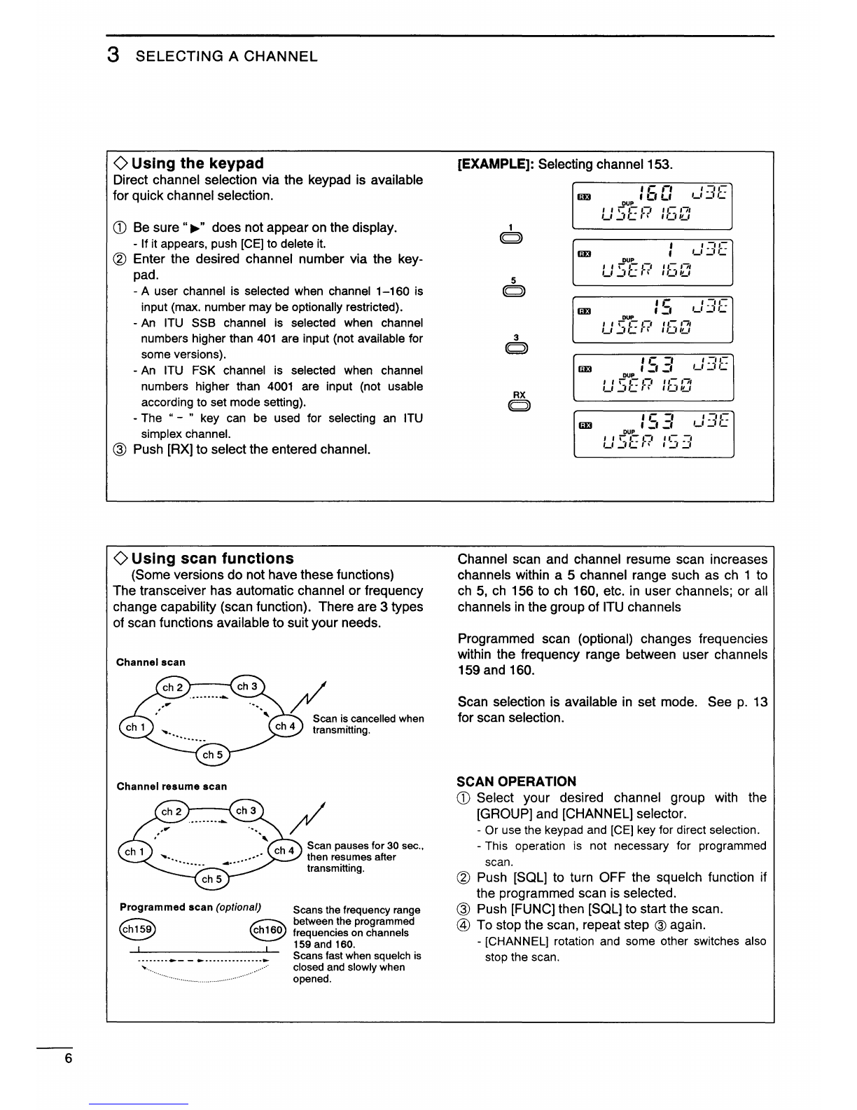
• Enters the selected channel number (or fre-
C
'V
quency*) for direct channel selection.
(p. 6)
• Stores a receive frequency into a user chan-
nel or ITU simplex channel when:
-pushing [CE]
("
...
"appears)
-entering the desired frequency via the keypad
-pushing and holding [RX]
(p.
9)
• Adjusts the RF gain after pushing [FUNC] to
reduce the receiver sensivity.
(p.
9)
rx
• Stores a transmit frequency into a
user
c::J channel (except General versions) when:
-pushing [TX]
("lEI
"blinks)
-pushing [CE] ("
...
"appears)
-entering the desired frequency via the keypad
-pushing and holding [TX]
(p.
11)
• Selects the transmitter channel for cross
channel operation (Europe versions only)
when:
-pushing [TX]
("lEI"
blinks)
-entering
the desired channel number via the
keypad
-pushing [TX]
(p.
1
0)
• Selects the transmit output power after
pushing [FUNC]. (p. 8)
cE
• Toggles the channel number input and fre-
C
--)
quency input*. (p. 7)
-
.....
n appears when frequency input* is se-
lected.
-The channel selector and keypad changes the
frequency while
.....
" appears.
• Clears the entered digit and retrieves the
previous channel (or frequency*) while en-
tering numbers. (p. 6)
• Enters
the
name programming condition,
after pushing [FUNC], for changing the
channel name. (p.
11)
C- J •
~oggles
the channel and frequency indica-
cHiFREO
tlons. (p. 5)
~
"-==./
to
0
C)
• Enters " - " for ITU simplex channels. (p. 6)
• Enter channel number with
up
to 4 or 5 digits
when ....." does not appear.
(p.
6)
• Enter the frequency with up to 6 digits* when
"
...
" appears.
(p.
7)
48
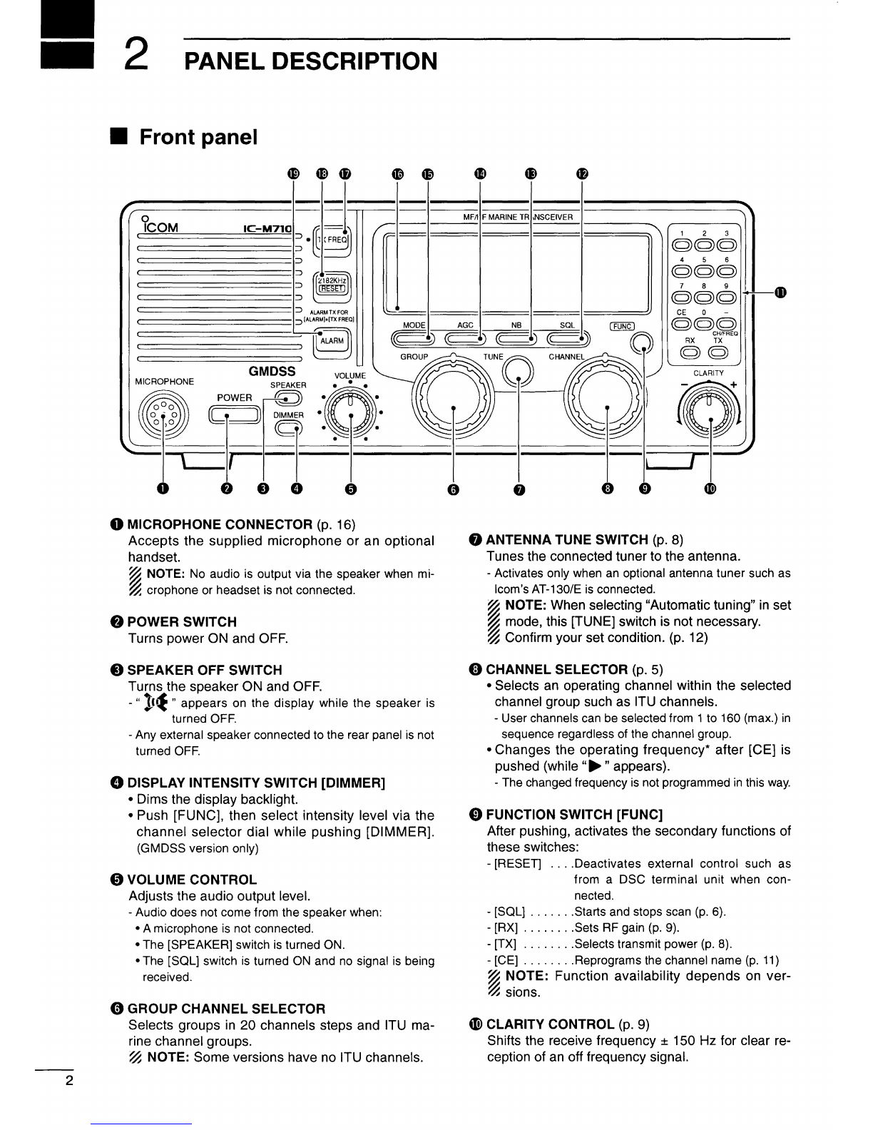
SQUELCH SWITCH [SQL) (p. 9)
• Activates the voice squelch function to reject un-
desired background noise while no signal is being
received.
PANEL DESCRIPTION 2
-The
squelch opens only when the received signal con-
tains voice or FSK components.
• Starts and stops the scan function after pushing
[FUNC]. (p. 6)
8 NOISE BLANKER SWITCH
[NB]
(p.
9)
Turns the noise blanker function ON to remove
pulse-type noise such as engine ignition noise.
-"NB" appears when the function
is
turned ON.
41
AGC OFF SWITCH [AGC) (p.
9)
Deactivates the AGC function to receive weak sig-
nals blocked by strong adjacent signals.
-"
)G(
"appears when the [AGC] switch
is
turned ON
(stands for AGC deactivated)
41
MODE SWITCH (p. 8)
Selects an operating mode temporarily. Available
modes differ according to version.
-J3E(USB), H3E, J2B(AFSK), FSK, R3E and
A1A(CW) modes are available.
-The temporary mode is cleared and the previous
mode appears when changing a channel.
4D
OVEN INDICATOR (GMDSS version only)
Internal high-stability crystal oscillator unit contains
a temperature-compensating oven heater. This
high-stability crystal oscillator improves frequency
stability.
41
TRANSMIT FREQUENCY SWITCH [TX FREQ]
(p.
8)
Displays the transmit frequency and opens the
squelch to check and monitor the transmit fre-
quency.
48
2182kHz SELECTION SWITCH
[2182KHz • IRESETI](pgs. ii, 5)
• Selects channel 0 (2182kHz; distress call fre-
quency).
-The
channel selector does not function when se-
lecting channel 0.
-Ignores external control and gives the front panel
control priority when
an
external controller (NMEA
format) is connected (except DSC terminal unit).
G)
ALARM SWITCH
(p.
ii)
• Emits a distress alarm signal from the speaker.
• Transmits a distress alarm or alarm testing signal
when pushed together with the [TX FREQ] switch.
~
NOTE: General versions are not equipped with
~this
[ALARM] switch.
*Some
versions do not have frequency selection and frequency indication. 3

4
2
PANEL
DESCRIPTION
0 ALARM INDICATOR (p. ii)
Appears
when
the
alarm function is activated
such for
an
alarm
test
or
distress alarm trans-
mission.
-Not available
on
General version.
8 RECEIVE INDICATOR (p. 9)
Appears
while receiving
and
when
the
squelch is
open.
@)
TUNE INDICATOR (p. 8)
Blinks while
the
connected antenna tuner, such
as
learn's AT-130/E, is being tuned.
-Tuning starts
when
transmitting
on
a new frequency
or pushing the [TUNE] switch.
0 TRANSMIT INDICATOR
•
Appears
while transmitting. (p. 8)
• Blinks when
the
[TX] key is pushed
for
transmit
frequency
programming. (p. 11)
0 DSC INDICATOR (p. ii)
Appears
when an optional GM-11ODSC
DSC
TER-
MINAL UNIT controls transceiver functions.
-The
GM-110DSC
can
be
connected
to
GMDSS
versions only.
0
S/RFMETER
•
Shows
the
relative received signal strength
while receiving.
•
Shows
output
power
while transmitting.
•
Shows
antenna
current level when an optional
AT-130E
HF
ANTENNA TUNER is connected
(Europe versions only).
0
CHANNELNAMEREADOUT
•
Shows
the pre-programmed channel name
(alphanumeric) during channel indication. (p.
5)
-Some versions have
no
channel name function
and
show receive frequency instead.
•
Shows
the
transmit
frequency
during
frequency
indication. (p. 5)
•
Shows
transmit
channel
number
during cross
channel operation (Europe versions only). (p. 10)
«3
SQUELCH INDICATOR (p. 9)
Appears when the squelch is ON.
0 SCAN INDICATOR (p. 6)
Appears when
the
scan
function is in use.
-The
scan
function
is
not available
on
some versions.
-Pushing [FUNC] then [SOL] starts
and
stops
scan.
~
FUNCTION INDICATOR
Appears when the [FUNC] switch is pushed.
-Some switches activate secondary functions.
G)
NOISE BLANKER INDICATOR (p. 9)
Appears when the [NB] switch is turned ON.
~
AGC OFF INDICATOR (p. 9)
Appears when the [AGC] switch is pushed to
indicate
the
AGC
function is deactivated.
Q)
MODE READOUT (p. 8)
Shows
the
selected operating
mode
(type
of
emis-
sion).
(D
SPEAKER OFF INDICATOR
Appears
when
the [SPEAKER] switch is pushed
to
indicate
the
front panel
speaker
is deactivated.
~
CHANNELREADOUT
•
Shows
the selected channel
number
during
channel indication. (p. 5)
•
Shows
the
receive
frequency
during frequency
indication. (p. 5)
~SIMPLEX/DUPLEX
INDICATORS
These
appear
to
show
whether
the selected chan-
nel is simplex
or
duplex.
(fj FREQUENCY INDICATORS (p. 7)
Appear
when the
frequency
entry condition* is
selected
for
frequency
selection.
-The
[CE]
key
toggles
the
indicator
ON
and
OFF.
*Some
versions have
no
frequency
entry condition.

SELECTING A
CHANNEL
3
• Selecting a channel
The transceiver has 160 user channels and
ITU
channels. However, the number of user channels
can be optionally restricted and ITU channels are not
available with some versions.
~
NOTE: When Channel 0 and/or 2182 kHz is se-
~
lected with the [2182KHz] switch, channel selec-
~
tion is NOT possible.
In
such a case, push
~
[2182KHz]
in
advance.
f I
Jf
I
II
f - f I
II
liD
•C•~•
I_I:JC
'-'
u:.Jc
CHANNEL
INDICATION -
DU~
- -
liD
DUP f
Lf Lf
_I
( I I i
_I
I I I 1
)I>
C
.0
:J
I:J,ILI
~
·-·-·-·-·-·-·-·-·-·-·-·-·-·-·-·-·-·-·-·-·-·-·-·-·-·-·-·-·-·-·-·-·-·-·-
¢=::>
··-·-·-·-·-·-·-·-
-·-·-·-·-·-·-·-·-·-·-·-·-·-·-·-·-·-·-·-·-
-·-
D
'-
I
_11
__
1 ;
'-
1
••
11._1 !
-.,-
-,-.,-,.,
CHIFREO
=·
c
=·
Cl
,,
I _
_,
I__
CE
-,
,
-,
,-,
,,
I I I
liiJ
!_
•
~~
-f
~~ ~~
l_l
-11
-
~
1aJ
)I>
1-
1-f
-,
1-f
I f 1_1
::_:1
C
DUP -
·-
- - -
FREQUENCY INDICATION
::1
C
."'J
0171
~~~
-,1-1171
LD~~U CD~~U
CHANNEL
SELECTION MODE
Channel can be selected
~
NOTE: Channel name (alphanumeric) does not appear during
~
channel indication according to set mode settings
(p.
13).
FREQUENCY SELECTION MODE
Frequency can be changed
<>
Using
the
channel
selector
[EXAMPLE]: Selection ofthe [GROUP] selector
The transceiver has two large controls for group
selection and channel selection. The [GROUP]
selector changes channels
in
20 channel increments
and selects
ITU
channel groups*; and the [CHAN-
NEL] selector selects each channel.
CD
Be
sure
no"~
..
indicator appears
on
the display.
II-
1-1
I
II
m:t I Cl
Ll
1
-1 :_-, C
DUP
...
s
:-
-:
:::•
/
r:,
:-
-:
:::•
~~
lf~ppears,
push [CE] to delete
it.
@ Rotate the [GROUP] selector to select the de-
sired channel group
as
shown at right and/or
below.
@ Rotate the [CHANNEL] selector to select the
desired channel.
[
1
J3E
I'·.
wwv
21
J3E
KMI
41
J3E
WOM
61
J3E
woo
121
J3EI
FAX . \
141
J3E
1···_/
\
SHP/SHP
,.'I
401
J3E
I
4.357.0 .
4-1
J3E
I
4A
LTD
601 J3E I
6.501.0
[
J3E
I
2501
26.145.0
[
25-1
J3E
l
.
. [ 4001 FSK] ]
4.210.5
1a
Q)
c:
c:
l1l
~
()
ID
1/)
1/)
::::l
t::
"
:.:::.!!!
1/)Ql
u..c:
c:
::::llll
f-~
-()
*AIIITU channels are not available with some versions and
ITU FSK channels can be hidden using set mode.
(p.
12)
CHANNEL GROUP
CHANNEL
NO.
DESCRIPTION CHANNEL
NO.
DESCRIPTION CHANNEL
NO.
DESCRIPTION
User channels 8·1 to 8-9 8 MHz ITU simplex channels 2201 to 2253 22 MHz ITU duplex channels
1
to
160 ([GROUP] selector changes in
20 channel steps) 1201 to 1241 12 MHz ITU duplex channels 22·1 to 22-9 22 MHz ITU simplex channels
401
to
427
4 MHz ITU duplex channels
12-1to12-9
12 MHz ITU simplex channels 2501 to 2553 25 MHz ITU duplex channels
4-1
to 4-9 4 MHz ITU simplex channels 1601 to1656 16 MHz ITU duplex channels 25-1
to
25-9
25 MHz ITU simplex channels
601
to 608 6 MHz ITU duplex channels 16-1 to 16-9 16 MHz ITU simplex channels ITU FSK duplex channels
6-1
to 6-9 6 MHz ITU simplex channels 1801
to
1815 18 MHz ITU duplex channels
4001
to
25040
(SITOR use)
801
to 832 8 MHz ITU duplex channels 1B-1 to 18-9 (No group separation)
18 MHz ITU simplex channels
5

6
3
SELECTING
A
CHANNEL
<>Using the keypad
Direct channel selection via the keypad
is
available
for quick channel selection.
CD
Be
sure
"...,.
..
does not appear
on
the display.
-If it appears, push [CE] to delete it.
® Enter the desired channel number via the key-
pad.
-A
user channel
is
selected when channel
1-160
is
input (max. number may be optionally restricted}.
-
An
ITU SSB channel
is
selected when channel
numbers higher than 401 are input (not available for
some versions}.
-
An
ITU FSK channel is selected when channel
numbers higher than 4001 are input (not usable
according to set mode setting).
-The " - " key can
be
used for selecting
an
ITU
simplex channel.
® Push [AX] to select the entered channel.
<>Using scan functions
(Some versions do not have these functions)
The transceiver has automatic channel or frequency
change capability (scan function). There are 3 types
of scan functions available to suit your needs.
Channel
scan
Channel resume
scan
/ Scan is cancelled when
transmitting.
Scan pauses for 30 sec.,
then resumes after
transmitting.
Programmed
scan
(optional) Scans the frequency range
~
~
between the programmed
~
~
frequencies on channels
159 and 160.
Scans fast when squelch is
closed and slowly when
opened.
[EXAMPLE]: Selecting channel153.
'r
,-,
llEt I
Cl
Ll
,_I
::..:II::
CUP
U
Sf
I~'
IGIZ:
Channel scan
and
channel resume scan increases
channels within a 5 channel range such as
ch
1 to
ch
5,
ch
156 to
ch
160, etc.
in
user channels; or all
channels
in
the group of
ITU
channels
Programmed scan (optional) changes frequencies
within the frequency range between user channels
159
and
160.
Scan selection
is
available
in
set mode. See
p.
13
for scan selection.
SCAN OPERATION
CD
Select your desired channel group
with
the
[GROUP] and [CHANNEL] selector.
-
Or
use the keypad and [CE] key for direct selection.
-This operation
is
not necessary for programmed
scan.
® Push
[SQL)
to
turn OFF the squelch function if
the programmed scan
is
selected.
® Push [FUNC] then
[SQL)
to
start the scan.
@
To
stop the scan, repeat step @again.
-[CHANNEL] rotation and some other switches also
stop the scan.

• Selecting a frequency
The transceiver has 0.5 to 30.0 MHz general cov-
erage receive capability with 100 Hz resolution. The
receive frequency can
be
changed instantly, indepen-
dent of the transmit frequency.
()Using
the
channel
selector
CD
Select a channel which is programmed near the
frequency you want receive.
<2)
Push the [CE] key to select frequency selection
mode.
-
"~"
appears
on
the display.
@ Rotate the [CHANNEL] selector to change the
frequency.
@ To return to the previous frequency, push [CE].
-
"~"
disappears and the previous frequency or
channel name appears.
()Using
the
keypad
~
CAUTION: A frequency can be entered into a
~
user channel or
ITU
simplex channel by pushing
~
the [RX] key. However, when pushing and hold-
~
ing
the [RX] key after entering a frequency, the
~
previously programmed contents are erased and
~
cannot
be
retrieved. Therefore, keypad entry
~
should
be
used only
on
spare channels.
CD
Select the memory channel to
be
used for gen-
eral coverage use.
I C ,-1
I
!..1
!..1
No
frequency programmed channel for general
coverage use.
(mode and channel name do not appear)
@ Push [CE] to select frequency selection mode.
@ Enter the desired frequency with 5 or 6 digits.
@ Push [RX] to input the frequency.
-Do
not
hold [RX] for more than 0.5 sec., otherwise
the frequency will be programmed into the channel.
SELECTING
A
CHANNEL
3
~
NOTE: The selected frequency is used for tempo-
~
rary receiving (transmitting is not available). This
~
frequency is cleared once the channel is changed.
~
~
If you want to program a frequency, refer to
p.
11,
~
memory programming.
~
CE
Q)
liil
Ill
I
Cl
!..1
'-'
:.1
,_:
DUP
SHF1/
SHP
'---1-------.J
No
"~"
indicator shows that the channel will
be changed when rotating [CHANNEL].
liif
I
II
laJ
I
Cl
!..1
1_1
:_1
c
DUP
...
,.-:•
:::,
::;
p
'//
~~-·-
-
-'·'-
"~"
and frequency show that the frequency
can be changed.
[EXAMPLE]: Setting 12.3450 MHz
I C
II
I
_I
!..1
Select non frequency I
programmed channel.
'-------------------~
CE
Q)
1
Q)
2 3
Q) Q)
4 5
Q) Q)
0
Q)
RX
(Q)
(momentarily)
...
...
I
I_
1 I
I
_I
!..1
I C
f'
I
-1 -1
I
. I
I
,-
,-1
I
=I
!..1
...
:,,~·]'·-IS
I C
II
I
_I
!..1
Iii-
I
::1 ::1
t J C:
171
''-·-'
1_1.1!....1
I I_ I I
I
_I
!..1
After temporarily receiving.
CE
Q)
I C ,-1
I
-1
!..1
7

8
4
RECEIVE
AND
TRANSMIT
• Basic voice receive and transmit
G)
Be sure of the following
in
advance:
• Microphone is connected.
• [SPEAKER] switch
is
turned OFF.
• [SOL] switch is turned OFF.
• [CLARITY] control is set to center position.
[SOL]
[CLARITY]
® Select the desired channel to
be
received with the
[GROUP] and [CHANNEL] selectors.
-When receiving a signal, S-meter shows its signal
strength.
• Functions for transmit
0
Transmit
frequency
check
When "DUP" appears
on
the display such as for a
ship-to-shore channel, the transmit frequency differs
from the received frequency.
In
such a case, the transmit frequency should
be
monitored before transmitting to prevent interference
to other stations.
<>
Transmit
power
selection
The transceiver has 3 selectable output powers.*
High power allows longer distance communications
and low power reduces power consumption.
*Only 2 selectable output powers are available with some
versions.
In
this case, level 1 stands for 60 W (the same
as
level2).
~
NOTE: Low power setting affects all channels ex-
~
cept the 2182 kHz emergency channel.
~
~
NOTE: Power selection
is
not possible with
~
GMDSS versions, only high power
is
available.
@ Adjust [VOLUME] to the desired audio level when
receiving a signal.
@ Push [MODE] to select the desired operating
mode, if the received signal is
in
a different mode.
@ Push [TUNE] to tune the antenna tuner, if con-
nected.
-This operation is not necessary when "automatic
tuning"
is
selected
in
set mode
(p.
12).
@ To transmit
on
the channel, push and hold the
PTT switch
on
the microphone.
-"TUNE" flashes for 1 to 2 sec. for the first trans-
mission
on
a channel when connecting
an
antenna
tuner.
(J)
After the flashing stops, speak into the micro-
phone at your normal voice level.
-The
RF meter shows the output power (or antenna
current) according to your voice level.
@ Release the PTT switch to return to receive.
• Push and hold the
[TX
FREQ] switch to monitor
the transmit frequency.
-The display shows the transmit frequency simulta-
neously.
CD
Push [FUNC] then [TX] to call
up
the following dis-
play.
3
}7F
--
P~Jf?
<V
Rotate the [CHANNEL] selector to select high or
low output power.
3
:high
power (150 W PEP)
2 :middle power (60 W PEP)
1 : low power (20 W PEP)
@ Push [FUNC] or [CE] to return to the previous dis-
play.

• Functions for receive
<>Squelch
function
This function detects signals with voice components
and
squelches (mutes) unwanted signals such as
non
modulated beat signals. This provides quiet
stand
by.
When
you
need to receive weak signals, the squelch
should
be
turned OFF.
<>Noise blanker
The noise blanker function reduces pulse type noise
such
as that coming from engine ignitions.
The noise blanker may distort reception of strong
signals.
In
such cases, the noise blanker should
be
turned OFF.
<>
AGC
off
function
The receiver gain is automatically adjusted accord-
ing
to
received signal strength with the AGC (Auto-
matic Gain Control) function
to
prevent distortion
from strong signals and to obtain a constant output
level.
When
receiving weak signals with adjacent strong
signals or noise, the AGC function may reduce the
sensitivity.
In
this situation, the AGC function
should
be
deactivated.
<>
RF gain setting
The receiver gain
can
be reduced with the
RF
gain
setting. This may help to remove undesired weak
signals while monitoring strong signals.
Usually, the AGC function reduces the
RF
gain
according
to
the receive signal strength and these
weak signals are removed. However, during periods
of
no
signals, these weak signals may not
be
heard.
In
such cases, the
RF
gain may
be
useful for setting
a minimum level at which
to
hear signals.
<>
Clarity
control
Voice signals received from other stations may
be
difficult
to
receive. This may sometimes happen if a
station
is
transmitting slightly off frequency.
In
such
cases, compensate the receive frequency only,
us-
ing
the [CLARITY] control.
RECEIVE
AND
TRANSMIT
4
• Push [SQL]
to
turn the squelch function
ON
and
OFF.
DUP
1r
n
I
Cl
!..I
,_:
j
1:.:
1-~
1'1
I
SQL
..._____
____
,_
"SQL"' appears when the squelch
is
ON
(noise
is
muted).
• Push
[NB]
to turn the noise blanker function
ON
and
OFF.
DUP
',-
n
I
Cl
!..I
,_:
:.:11:.:
1-U"I
I N B
'----------1-
"NB" appears when the noise blanker
is
ON.
• Push [AGC] to deactivate or activate the AGC
function.
'r
r•
lll3 I Cl
!..I
:·~
r~:
I I : •
-::·.
--~
Appears when the [AGC) switch
is
ON
(AGC function deactivates).
G)
Push [FUNC] then
[RX]
to call
up
the following
display.
Cl
_I
,-,,-
,-
,-,
T
II
I
,.,
,..-
·-,~,r-,
..L,
~•
® Rotate the [CHANNEL] selector to set the de-
sired minimum cutting level.
-"0" to "9" are available.
-S-meter shows the minimum permitted level.
@ Push
[FUN
C) or
[CE]
to
exit the
RF
gain display.
• Adjust [CLARITY] to improve the audio signal.
~[
9

10
4
RECEIVE
AND
TRANSMIT
• CW operation (Marine/General versions only)
The transceiver has the following
CW
keying fea-
tures and they can be selected
in
set mode as
described on
p.
14
• Full break-in (receiving is possible
while
transmitting)
• Delay keying (automatic transmission
with
keying)
• OFF
(manual
transmission
is
necessary before
keying)
CD
Connect a
CW
keyer
or
an external electronic
keyer to the ACC(1) socket as shown
at
right.
(g)
Selectthe desired channel to operate
CW
mode.
@ When the selected channel is not
in
A1A
mode,
push [MODE] one
or
more times to select
"A
1A."
@ Operate the
CW
keyer to transmit a
CW
signal.
~
CW
mode
may
not
be
used
depending
on
versions.
~
CW
narrow
can
be
selected
in
set
mode
(p.
13)
when
~
an
optional
filter
is
installed
(already
built-in
to
the
GMDSS
~
versions).
CW
key connection
CWkey
ACC(1)
socket
• FSK operation (Marine/General versions only)
The transceiver has FSK and
J2B
modes for FSK
operation. Use the FSK mode when using the
oscillator
in
the transceiver and use the J2B mode
when using an
AFSK
terminal unit.
CD
Connect an FSKterminal unit as shown at right.
(g)
Select the desired channel.
-
FSK
ITU
channel
group,
ch
4001
to
ch
25040,
are
available depending
on
versions.
@ Push [MODE] one
or
more times to select the
type
of
emission as "FSK"
or
"J2B."
@ Operate the FSK terminal unit.
~
FSK
shift frequency
and
FSK
polarity
can
be
adjusted
~
in
set
mode
(pgs.
13,
14).
NOTE:
Some
transceivers
may
operate 1
.7
kHz
higher
than
the
IC-M71
O's
J2B
mode
even
when
the
same
displayed frequencies
are
in
use
.
FSK terminal unitconnection
ACC(1)
socket
FSK
terminal unit
• Cross channel operation (Europe versions only)
Cross channel operation is available with some
versions to operate different channels for receiving
and transmitting.
CD
Select the desired channel for receiving.
-
ITU
simplex channels cannot
be
used
for
cross
channel
operation.
(g)
Push
[TX],
then select the desired channel for
transmitting.
-
"ID"
blinks after
pushing
[TX].
@ Push
[TX]
again to stop the blinking.
@ Operate the transceiver normally.
@ Change the channel to clear the cross channel
setting.
Cross channel operation example
I C
:1
C
llJ3 I
!..1
-1 -1
DUP
I
-,
.::r
I.
_I
I
__
1
f71
I 1._1 I
I.ILI
'
While
receiving
,_:
::.3l:
:
c'
c:
El
._:
:::
~:.:
DUP
o:t
I-,-,,- 1171
..!££_:..:.!...1':!-
0 ' 2 J 4
While
transmitting
~
NOTE: This function is available for the
~Europe
versions only.

USER
CHANNEL
PROGRAMMING
5
• Programming a frequency
The IC-M710 has up to
160
user-programmable
channels each with channel name capability
of
up to
7 alphanumeric characters.
<>Receive
frequency
CD
Select the desired
user
channel to be pro-
grammed.
-Channels 1
to
160
(maximum)
are
programmable.
® Push [CE]
to
select frequency selection mode.
-".,.. •
and
frequency appear
on
the display.
@ Enter the desired
frequency
via the keypad with
5
or
6 digits.
-Or
rotate the [CHANNEL] selector
to
change
the
frequency.
@
To
change the operating mode (type
of
emis-
sion), push [MODE] one
or
more times.
@ Push and hold [RX] for 1 sec. to program the
user channel.
~
NOTE: ITU simplex channels can be programmed
~
as well as user channels. However, transmit fre-
~
quencies cannot be programmed (not necessary
to
~program).
Push
[CE]
Set
frequency.
Push
and
hold
[RX].
:so
,_/:://:.:
DUP
~
.~·
c·.:=:
:z:
:.:J
Frequency
and
"._"
appear.
:so
l_l::/1:.:
DUP
1-1
-~
-~
Cl
rl1
0.
ICI..J.ILI
Use
keypad
or
channel
selector.
:
E.r::
,_:::~::.:
DUP
I
I\,-
1-1
II-
r71
1_1
_JC
(>
I(JI!...I
Programming
is
completed.
<>Transmit
frequency
(Not applicable
for
General versons)
CD
Select the desired
user
channel to be pro-
grammed.
® Push [TX].
-
"iD"
blinks.
@ Push [CE] to select frequency selection mode.
-".,.."
and
frequency appears
on
the
display.
@ Enter the desired frequency
via
the keypad with
5
or
6 digits.
-
The
[CHANNEL] selector cannot
be
used.
-Refer to
p.
23
for programmable frequency
range
(frequency coverage, transmit).
® Push and hold [TX] for 1 sec.
to
program.
@ Push
[TX]
to clear the
"w"
blinking.
0 Channel
name
CD
Select the desired
user
channel to be pro-
grammed.
® Push [CH/FREQ] to select channel indication.
® Push [FUNC] then [CE].
-
The
channel name (alphanumeric) readout blinks.
@ Rotate the [GROUP] selector
for
cursor position
and the [CHANNEL] selector for the message
contents.
-
To
return to the previous message,
push
[CE).
® Push and hold [RX] to program the message.
-
Blinking
stops.
• Available
characters
111
,-,
II-I
to
::..:r
,-,
7
,-
·1
to
!...
_ (space)
I I \
\II
f I I '
-,
I ,
,,,
-,-
--
I L
::
....!
(!.1
Push
[TX).
Push
[CE]
Push
and
hold
[TX]
after
entering
a
frequency.
Push
[FUNC]
then
[CE]
Rotate
[GROUP]
and
[CHANNEL]
to
select
cursor
and
character.
Push
[RX].
f
,,,,Ill
lliJ
I
Cl
!..1
1_1
::..::r
C
X
J:f-
I I
,!'~~
1-1
I
1-
111
f 1
'-
1_1
...JC
(i
I(JI!..I
"m"
blinks.
f
I-
-~
lliJ
I b
L,
,_/::/1:.:
_l'
~~
:-:1
.-:.UP
I
Ill
1::
111
t I
'-
I_
1_,
I
1!...1
_1,1!...1
[
IC.rl
'·-''--
lliJ
I
!..1 !..1
1_1
_I
I_
':\.
I / OUP
-Lm-'
,,,-,-,
,,-,,,
rI
'-
1_1
~IC
(i
1(....11!...1
I
C.
,-,
lliJ
I
!..1 !..1
'-
I / DUP
-:
:s:,r-:F?
:sr:
/,,--
lliJ
I
C.
,-,
DUP I
'-'
"'I
/
,-
,-'"'''-
h...J.
T _
I_
1_11
II:_:
I~~
I
/I'
I
C.
II
lliJ
I
!..1 !..1
DUP
,-,-,Hill-hIT
I_
1_11
1(_:1
\I'
I.
II
~-~~~c
,_/:://:.:
,_/::/1:.:
~Channel
name
programming
is
inhibited
on
some
~versions.
11

12
6
SET
MODE
• Set mode operation
Set mode operation is used for programming infre-
quently changed values or conditions of functions.
The
IC-M71
0 has up to 13 such items.
~
Some of the set mode items described
in
this
~
section are not available on some transceiver ver-
~
.
~
SIOnS.
CD
Push [POWER] to turn power OFF.
® While pushing and holding [FUNC] and
[1],
turn
power
ON
to enter set mode.
-Set mode is selected and one
of
its items appears.
@ Rotate the [GROUP] selector to select the desired
item.
@ Rotate the [CHANNEL] selector to set the values
or conditions for the selected item.
@ Turn power OFF and
ON
again to exit set mode.
• Set mode contents
(1) FSK ITU
channels
FSK ITU channels appear as a group between the
ITU
25 MHz band and user channels. This FSK
channel group can
be
hidden for voice communi-
cation use only.
(2) Connected antenna
tuner
The transceiver has several tuner control systems
for use with
an
optional lcom antenna tuner. Select
the condition depending
on
the connected antenna
tuner.
Note that internal switch selection may
be
required
when using a non-lcom tuner
(p.
19).
(3)
Automatic
tuning
condition
When the optional AT-130 or AT-130E AUTOMATIC
ANTENNA TUNER is connected, tuning can
be
started
automatically without the [TUNE] switch for instant
operation.
If manual tuning is required, this automatic operation
can
be
deactivated.
[POWER]
F/
t - /
=/
[/
~--;--(Condition
T
:_:r.:E
f'?
Item
r
,-
CI
,-
,-
1-
T
T,-,,-,
:J .L •
,_,,...~
FSK channels do not
appear (no SITOR
operation).
~--------~~efuu~
Cl
,-1
,-
T T
,-,,-,
::I.J..
I
l_l(i
:=:
t -I
-1
,-,
I
=I
!...I
T 1
111
,-
,-,
I
'-"
·•C
(i
:=:t-
:c•c:
T 1
'"
•C:
,_.-')
'
,_,,~··-I
I
:=:
:-:
-
=:
T1
lhlf:(-')
',_,,~,,_,,
c•
.-.
r:ur T I
111
I
',_,,,,
FSK channels appear (for
SITOR operation).
AT-130
(default)
AT-120
AH-3
Tuning starts when
pushing [PTT]
on
a new
..____
________
____,
frequency.
r:ur T 1
lh
1
I'-''''
L_
________
_J
Tuning starts only when
(TUNER] is pushed.
(default)

(4)
Scan
type
selection
(scan-type only)
This item selects one
of
the following scan functions.
Channel scan and channel resume scan search 5
channels around a user selected channel
or
search
all ITU channels
in
the band when an ITU channel is
selected.
Programmed scan (optional) searches signals within
the frequency range and activates slowly while
squelch is open and fast while squelch is closed.
(5)
Scan
speed
(scan type only)
Selects scan speed as follows: (unit: msec./ch)
Selection 1 2 3 4 5 6 7 8 9
Channel scan 130 260 520 1040 2080 4160 8320
16460
33280
Channel resume
scan (sec./ch) 1 2 3 4 5 6 7 8 9
Programmed scan
(squelch open*) 10 20 40 60 90 140 210 320
480
*squelch closed: 10 ms/ch
-Fast
speed Slow
speed-
(6)
Channel
name
and
frequency
The lower half of the display can be set to display a
programmable channel name or a receive frequency
according to an operator's needs.
(7) CW/FSK
narrow
filter
This item selects the passband width for A1A (CW),
FSK or J2B mode.
~
NOTE: When "on" is selected without optional
~
filter installation, the Marine and General versions
~
do not function on these modes. The GMDSS
~
versions can use "on" as standard.
(8)
FSK
shift
frequency
Several shift frequencies (the difference between the
mark and space frequency) are used for FSK opera-
tion. This item allows you to select a shift frequency
for almost any FSK system.
10
66560
10
720
SET
MODE
6
.---~-~~------------~channel
scan
L
f-/
Scan
is
canceled when
S[
--
T
~~
F'
[ transmitting.
....___
__________________
____.,
(default)
.---~-~~------:::_:-::_:------~
Channel resume scan
,_'
:-,'
-
,-
:-
-'-,
....
Scan pauses when trans-
S[
--
T
~~
F'
[ mitting, then resumes after
'-------------------------"
30 sec.
p
,-
_,-,
Programmed scan
Scan operates over the
S[
--
T \1 p [ frequency range.
'-------------------------"
(optional)
I
f Fastest scan speed
SC --SF'II
(default:
4)
I ,-1
f
'-'
SC
·-SF']
Slowest scan speed
.-----~-~~~--~-~------,Channel
number
L
f-,
-L Cl and channel name
I~
1·-:
--
] I 5
:::•
(alphanumeric)
'-------------------------'
(default)
[
:-:
-
:-
,-
,-,,TIT',,-,
,_
,.
-,
..
..!..1
..!..
_:.,--
c,F
:=
r.:F:f?
--
r=
I L
....___
__________________
____.,
o,-,
r.::-1:~·--
F IL
Channel number
and frequency
Passband:
2.3
kHz/-
6 dB
(default)
Passband:
500
Hz/-6
dB
(for General/Marine ver.)
....._
__________________
___)
350
Hz/-6
dB
I
-1
,-1
I f '-1
:::
s:-~
--
s:::
r
0 c
,-1
'-1
_,
'-'
:::
S
:-:
--
S
:--:
T
(for GMDSS versions)
Shift frequency:
170Hz
(default)
Shift frequency:
425Hz
Shift frequency:
850Hz
13

14
6
SET
MODE
(9) FSK
polarity
Normal
and
reverse polarities are available for FSK
operation. This item allows you to select one of
these polarities.
"FSK-REV off" (normal):
key open (mark); key close (space)
"FSK-REV on" (reverse):
key open (space); key close(mark)
(1
0) CW break-in
CW break-in function
(in
A1A mode) toggles transmit
and receive with CW keying. Full break-in allows
you to receive signals between transmitted keying
pulses during CW transmission. Semi break-in
allows you
to
mute receiving until keying stops
with
some delay time.
(11) LCD
contrast
The
LCD
contrast
can
be
adjusted through 10 levels
to
suit transceiver mounting angle, location
and
ambient lighting.
(12)
ID
number
setting
for
remote
control
When connecting
an
external controller such as a
personal computer, 2-digit
ID
codes are required to
access the transceiver. The
IC-M71
0 adopts
NMEA0183 format
and
uses a "proprietary sen-
tence" for remote control.
(13) Remote
control
input
terminal
Remote control signals can
be
input via the [DSC]
(or REMOTE) socket or [CLONE] jack.
oFF
:::
5
f~
--::;•
EI/
c,.-,
:::
s:-:
--
r~·:~
:,~
C
Ill
I
I
LIL
L
C
J,J
··
f::-:
I
1\1
FSK normal
(default)
FSK reverse
Full break-in
Automatic keying without
delay time
'-----------_/(default)
dELt=l'd
c
:~~:
--
:m:
I
r.:
C1
f- f-
,-,
I
Till
Till
'-
1"1
--
:0
(\
.!..
I
''
L_
_________
_J
,-,
I
Ll
I
:_
CII··
Cr.:
T
,,-,
ILl
I_:~
II·-
[
l\1
T
1-1
I
Ll
I
::?[1"1
T
··I
II
CICI
-1-1
T
T1
..L
..LI
l_l
-C I
f-
_l
_l_l_l
::-·?
:~
r':
T
·-
I:::
p
,.-,
Semi break-in
Automatic keying with
delay time
OFF
Manual transmission
necessary for keying
Lowest contrast
(default:
7)
Highest contrast
NMEA
ID:
"1"
(default)
NMEA
ID:
"99"
[DSCJ (or REMOTE
according
to
version)
socket
(default)
[CLONE] jack

CONNECTIONS
AND
INSTALLATION
7
• Connections on rear panel
0 ANTENNA CONNECTOR (p. 19)
Connects a 50 Q HF band antenna with a 50 Q
matched coaxial cable and a PL-259 plug.
8 GROUND TERMINAL (p. 18)
IMPORTANT! Connects a ship's (or vehicle's)
ground. See
p.
18 for details.
8 ACC(1)
and
ACC(2) SOCKETS
See
p.
16 for details
8
CLONEJACK
For Dealer use only.
0 DSC
or
REMOTE SOCKETS
• DSC socket for GMDSS versions -Connects
an
optional GM-110DSC DSC TERMINAL UNIT
for DSC operation.
• REMOTE socket for Marine and General ver-
sions.
0 MOD/AF SOCKET (GMDSS versions only)
Connects
an
external terminal
unit
• Unpacking
NOTE:
To
meet the European GMDSS regula-
tions, the following must be connected to the
IC-M710GMDSS version:
• GM-110 DSCTERMINALUNIT
• PS-65 (or 66) DC-DC
coN-
VERTER
UNIT
• AT-130E AUTOMATIC AN-
TENNA
TUNER
12 V battery
6
EXTERNALSPEAKERJACK
Connects a
4-16
Q external speaker using a 1/4
inch monaural plug. This external audio is not
muted by the [SPEAKER] switch
on
the front
panel.
C) TUNER RECEPTACLE
Connects a control cable to an optional AT-130 or
AT-130E ANTENNA TUNER. A female connector
is supplied for connection.
@)
DC POWER RECEPTACLE
Connects to a regulated
12-16
V DC power
source such as 12 V battery or DC power supply
using the supplied DC power cable.
CAUTION: DO NOT connect to a 24 V battery.
This will damage the transceiver.
«!)
FUSE HOLDERS
Hold two 30 A fuses for
E6
and 8 terminals.
Replace both fuses when one fuse is blown.
Microphone (EM-101)*
.............
1 DIN connector (7-pin for ACC2)
......
1 Nuts (M6; use 2 pes. for each bolt) . . . 8
Flat washers (M6) . . . . . . . . . . . . . . . . . 8
Microphone hanger . . . . . . . . . . . . . . . 1
DC
power cable (OPC-568)
.........
1
Mounting bracket . . . . . . . . . . . . . . . . . 1
Bracket knobs (8820000170)
..
_
.....
4
*Some versions have no microphone sup-
plied.
CONNECTORS
DIN
connector (8-pin for ACC1)
......
1
Speaker plug (5610000040)
.........
1
Tuner connector (56100000150)
.....
1
Pins for tuner connector (6510019030). 4
DIN connector cover (GMDSS only)
...
1
(attach to the ACC sockets)
NUTS AND BOLTS
Allen bolt (M6 x 50) . . . . . . . . . . . . . . . 4
Self-tapping screws (M6 x 30) . . . . . 4
Spring washers (M6)
..............
4
Self-tapping screws
(3.5 x 30 for mic. hanger)
.......
2
FUSES
FGB 30A (for rear panel) . . . . . . . . . . . 2
FGB 5 A (for inside)
...............
2
15

7
CONNECTIONS
AND
INSTALLATION
• Connector information
ACC(1)*
PIN PIN
NAME
DESCRIPTION
SPECIFICATIONS
1
CWK
CW and FSK keying input. Input level : Less then 0.6 V for transmit
~
2
GND
Connects to ground. Connected
in
parallel with ACC(2)
pin
2.
Input/output
pin.
Ground level
-0.5
to 0.8 V
3
SEND
Goes to ground when transmitting. Input current Less than
20
rnA
When grounded. transmits. Connected
in
parallel with ACC(2)
pin
3.
Rear
panel
4
MOD
Modulator input. Input impedance
10
kQ
view
Usable when pin 3
is
grounded. Input level Approx. 100
mV
rms.
5
AF
AF detectoroutput. Output impedance : 4.7 kQ
Fixed, regardless of [AF] position. Output level :
100-300
mV
rms
6
SCAN
Starts scan when grounded. Scan operation : Less than 0.6 V
7
13.6
v 13.6 V output when power
is
ON.
Output current : Max.1 A
Connected
in
parallel with ACC(2)
pin
7.
Control voltage
-3
to
0 V
8
ALC
ALC voltage input. Input impedance More than 10
kQ
Connected
in
parallel with ACC(2)
pin
5.
* ACC{1
):
Manne
and
general
verston
only.
ACC(2)*/ACC*
PIN PIN
NAME
DESCRIPTION
SPECIFICATIONS
(Marine/General versions) 1
8V
Regulated 8 V output. Output voltage : 8 v ± 0.3 v
Output current : Less than 10
rnA
@ 2
GND
Same as ACC(1) pin 2.
3
SEND
Same as ACC(1) pin
3.
4
NC
No connection
5
ALC
Same as ACC(1) pin
8.
Rear
panel
view
6
RLC
T/R relay control output When transmitting : 0 V (less than 0.5
A)
7
13.6V
Same
as
ACC(1)
pin
7.
•
ACC{2):
Marine
and
general
version,
ACC:
GMDSS
version.
MICROPHONE
PIN
PIN
NAME
DESCRIPTION
SPECIFICATIONS
1
MIC+
Audio input from the microphone Input impedance :
600Q
element.
2
NC
No
connection
3 AF1 AF output controlled with [VOLUME]. Output impedance :
4Q
(~
~:~1)
Connected to
pin
4
in
the microphone.
4
AF2
AFinput
Connected
to
pin
3
in
the microphone.
30
06 5
PTT
PTT switch input
~o
o_0
When grounded, transmits.
--=-
6
GND
Connected
to
ground.
7
MIC-
Coaxial ground
forMIC+
8
AF-
Coaxial ground for
AF1
and AF2.
TUNER
PIN PIN
NAME
DESCRIPTION
SPECIFICATIONS
1
KEY
Key signal input
-0.5
to 0.8 V during tuning
1 2
• 2
START
Start signal output Pulled up 8
V,
0
V(1
00 msec.) as a start signal.
3
13.6V
13.6 V output Maximum current
2A
E
8terminal
For U.S.A. version (See below for Europe version)
3 4 4 ................
·····································-------------
--------------------------------------------------------------
ANTC
Antenna current input Input level : Approx. 2 Vrms
16
Other manuals for IC-M710
5
Table of contents
Other Icom Transceiver manuals