manuals.online logo
Brands
  1. Home
  2. •
  3. Brands
  4. •
  5. Icom
  6. •
  7. Tuner
  8. •
  9. Icom AH-4 User manual

Icom AH-4 User manual

INSTRUCTIONS
HF + 50 MHz AUTOMATIC ANTENNA TUNER
1-1-32 Kamiminami, Hirano-ku, Osaka 547-0003, Japan
Dec. 2020
A8295W-1EX-3 Printed in Japan
© 1997–2020 Icom Inc. –1 –
–4 –
AH-4
Thank you for purchasing the AH-4 HF + 50 MHz
AUTOMATIC ANTENNA TUNER. The AH-4 matches
your transceiver to an antenna more than 7 m/23 ft long
(3.5–54 MHz), or the optional AH-2b (7–54 MHz).
Please read these instructions thoroughly before
installing and operating the AH-4.
qU-bolts ………………………………………………………2
wU-bolt brackets ……………………………………………2
eFlat washers (M6 large) ……………………………………8
rFlat washers (M6 small)……………………………………4
tSpring washers (M6) ………………………………………8
yNuts (M6) ……………………………………………………8
uHex head bolts (M6 ×50) …………………………………4
iSelf-tapping screws (A0 6 ×30) …………………………4
oPL-259 connectors …………………………………………2
!0 Weatherproof cap …………………………………………1
!1 Rubber vulcanizing tape …………………………………1
Control cable* (5 m; 16.4 ft) …………………………………1
Coaxial cable* (5D-2V: 5 m; 16.4 ft)…………………………1
*Not shown in the illustration to the left.
RNEVER operate this tuner without a solid ground. Always
connect the ground wire to the ground terminal. DO NOT
use the mounting plate as a ground terminal.
NEVER transmit or tune without an antenna connected.
Failure to use an antenna will damage the tuner.
RHIGH VOLTAGE! NEVER touch the antenna while
transmitting or tuning. Place the antenna in a position where
you are sure it will not be touched.
DANGER!
❍WIDE TUNING RANGE
The AH-4 provides reliable matching from 3.5 MHz to 54 MHz
when using at least a 7 m (23 ft) antenna; or 7 MHz to 54 MHz
when using the AH-2b .
❍AUTOMATIC DIGITAL CONTROL TUNING
The built-in 8-bit microprocessor chooses the lowest SWR using
󰀨
❍45 FREQUENCY MEMORIES FOR FAST TUNING
The LC combinations of 45 previously-used frequencies are
automatically memorized. Once a frequency is memorized, the
AH-4 tunes on that frequency in less than 1 second. Note that
the AH-4 does not memorize a frequency which is normally
tuned within 2.5 seconds. Memories are retained only when the
power is on.
❍WEATHERPROOF DESIGN
The AH-4’s tightly sealed plastic case allows convenient
mounting virtually anywhere. The AH-4 can be mounted
outdoors under your antenna.
❍0.3 W RADIATED POWER
Radiated power during tuning is less than 0.3 W, minimizing
interference to other stations.
✍NOTE:
The AH-4 can be used with most of Icom HF transceiver,
which covers HF through 50 MHz bands.
However, the IC-706 and IC-736 can only be tuned in the
3.5–30 MHz range.
FEATURES
SUPPLIED ACCESSORIES
Ground terminal
Mounting plate
q
w
e
r
t
y
u
i
o!
0
!1
Tuning is required for each frequency. Be sure to retune
the antenna before transmitting when you change the
frequency— even slightly.
(eg. IC-7300)
qTurn ON the transceiver.
• Each time you push
TUNER
, “TUNE” is displayed or goes
out, and the AH-4 is turned ON or OFF (bypassed).
wHold down
TUNER
for 1 second to start manual tuning.
• The tuner reduces the SWR to less than 2:1 after 2~3 seconds
of tuning.
LWhile tuning, “TUNE” blinks red.
LIf the tuner cannot reduce the SWR to less than 2:1 after 15
seconds of tuning, “TUNE” goes out.
Hold down [TUNER] for 1 second.
eAfter tuning, “TUNE” is displayed.
LWhen the long wire antenna cannot be tuned, “TUNE” goes
out. In that case, the AH-4 is bypassed and the wire is directly
connected.
NOTE:
 
length and connection. Note that the AH-4 cannot tune a

OPERATION
DSpecications
• Frequency range : 3.5–54 MHz (with an antenna longer
than 7 m; 23 ft)
7–54 MHz (with the AH-2b)
• Maximum input power : 120 W
 
• Tuning power required : 5 to15 watts
• Rated voltage : 13.8 V DC ±15%
(current less than 1 A)
• Usable temperature range : –10°C to +60°C (+14°F to +140°F)
• VSWR : 2.0 : 1 or less (except antennas a
one half wave or multiple of a one
half wave in length)
• Weight (approximately) : 1.2 kg (2.65 lb)
• Dimensions : 172(W) × 69.5(H) × 230(D) mm
(projections not included) ; 6.8(W) × 2.7(H) × 9.1(D) inches
 Allspecicationsaresubjecttochangewithoutnoticeorobligation.
DOptions
•OPC-420 
Shielded control cable helps protect the transceiver from RF
feedback and extends separation between tuner and transceiver
up to 10 m. (cable length 10 m; 32.8 ft)
•AH-2b 
A 2.5 m long antenna element for mobile operation with AH-4.
Frequency coverage: 7–54 MHz with the AH-4.
SPECIFICATIONS AND OPTIONS
Fig.5MOUNTINGEXAMPLES
RDANGER! HIGH VOLTAGE! NEVER touch the antenna while transmitting or tuning. Place the antenna in a position
where you are sure it will not be touched.
AH-2b + long wire
AH-2b

(optional)
Long wire
Long wire
–3 –– 2 –
Fig.4MOUNTINGTHEAH-4
• Mountingonanantennapole
Using the supplied U-bolts
CAUTION:
DO NOT mount the antenna tuner upside down.
• Mountingonaatlocation
Using self-tapping screws Using nuts and bolts
Nut
AH-4
Spring
washer
Flat
washer
Hex head
bolt
Drill a hole here
(diameter: 6.6–7 mm;
1
⁄4–
9
⁄32 inches)
Weatherproof cap
Fig.2-2Waterproongtheantennaconnection
Carefully bend this
part up, AFTER
you tighten the
wing nut.
Pull the tape to slightly
stretch it as you wrap
firmly around the
weatherproof cap.
Rubber vulcanizing tape
q w e
Insulator
Fig.3GROUNDCONNECTIONS
The ground wire of the antenna tuner is used as an
antenna element. The transceiver and antenna tuner
must have an adequate ground connection. Otherwise,
󰀩
installation will be reduced. Interference, RF feedback and
electrical shocks from other equipment could also occur.
For best results, use the heaviest gauge wire or strap
available, and make the connection as short as possible.
(see the illustration to the right)
• A long wire connected to the GND terminal as a counterpoise is
also acceptable.
Copper pipe Metal object Copper screen
To the AH-4 GND terminal
✍ NOTE: After inserting the coaxial cable through the
waterproof cap and into the AH-4 top cover, solder the
PL-259 connector to the coaxial cable.
qRemove the top cover (Fig. 1).
wInstall the control cable and coaxial cable (Fig. 1).
eConnect and solder the PL-259 connector to the coaxial
cable.
rConnect the control cable to the AH-4 (Fig. 2-1).
tConnect the GND cable to the AH-4 (Fig. 3).
yReplace the top cover.
uMount the AH-4 in the desired location; on an antenna
pole, in your vehicle’s trunk, and so on. (Fig. 4).
iConnect an antenna to the AH-4 (Fig. 5).
oConnect the control cable and the coaxial cable to the
transceiver.
INSTALLATION
Fig.2-1CABLECONNECTIONS (eg. IC-7300)
Fig.1COVERREMOVALANDCABLEINSTALLATION
Strain relief
insert
Coaxial
cable
Rubber seal
Control
cable
Cable
clamp
Abouttherubberseal
Bottom cover Bottom cover
Rubber seal
Groove
Correct position Incorrect position
qRemove the 8 screws from the top cover and remove the cover.
wLoosen the screws on both cable clamps. If desired, install a strain
relief insert (supplied) corresponding to the diameter of the cable.
eInstall the coaxial cable through the top cover cable clamp.
rInsert the control cable through the bottom cover cable clamp.
tAfter connecting the coaxial cable and control cables, tighten the
cable clamp screws.
NOTE:
• Make sure the cable clamps are well tightened with the screws,
otherwise the waterproof protection may not be guaranteed.
• We recommend that you also wrap rubber vulcanizing tape or

NOTE:
When attaching the tuner cover, make sure dust or other material does
not adhere to the rubber seal. If dust or other material is on the seal
when attaching, waterproof protection may not be guaranteed.
Make sure the rubber seal is properly seated into the groove.
Wing nut
Star washer
Crimp-on wire
terminal
Flat washer
Base nut
Insulator
Coaxial cable
IC-7300 rear panel
Control cable
Bottom
cover
GND
Top cover
PL-259
connector
Antenna element
AH-2b (optional)
J8
J2
Black (GND)
Red (DC13V)
White (START)
Green (KEY)
GND
+SeetheFig.2-2asshowntotherightabove.
q
and then wing nut on the base bolt. Then, tighten the
wing nut.
• Before you tighten the wing nut, make sure the base nut is

• After you tighten the wing nut, carefully bend the wire
terminal up so the wire lines up with the insulator.
wPlace the weatherproof cap over as much of the
insulator as possible.
eWrap the insulator with the rubber vulcanizing tape,

antenna wire.
This will help prevent water seepage.
• Also, you may wrap electrical tape over the wrapped rubber

✍NOTE: Connect the coaxial cable to the appropriate antenna
connector if the transceiver has more than one.
See your transceiver’s instruction manual for details.

Other manuals for AH-4

5

Other Icom Tuner manuals

Icom AT-130 User manual

Icom

Icom AT-130 User manual

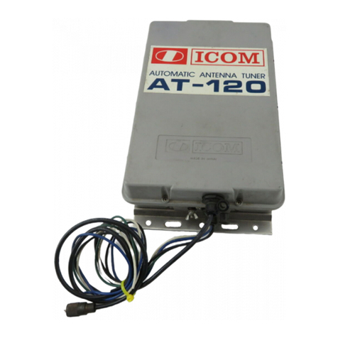
Icom AT-120 User manual

Icom

Icom AT-120 User manual

Icom AH-3 User manual

Icom

Icom AH-3 User manual

Icom IC-AT500 User manual

Icom

Icom IC-AT500 User manual

Icom AH-4 User manual

Icom

Icom AH-4 User manual

Icom AT-120 User manual

Icom

Icom AT-120 User manual

Icom AH-4 User manual

Icom

Icom AH-4 User manual

Icom IC-718 User manual

Icom

Icom IC-718 User manual

Icom AT-130 User manual

Icom

Icom AT-130 User manual

Icom AT-130 User manual

Icom

Icom AT-130 User manual

Icom AT-141 User manual

Icom

Icom AT-141 User manual

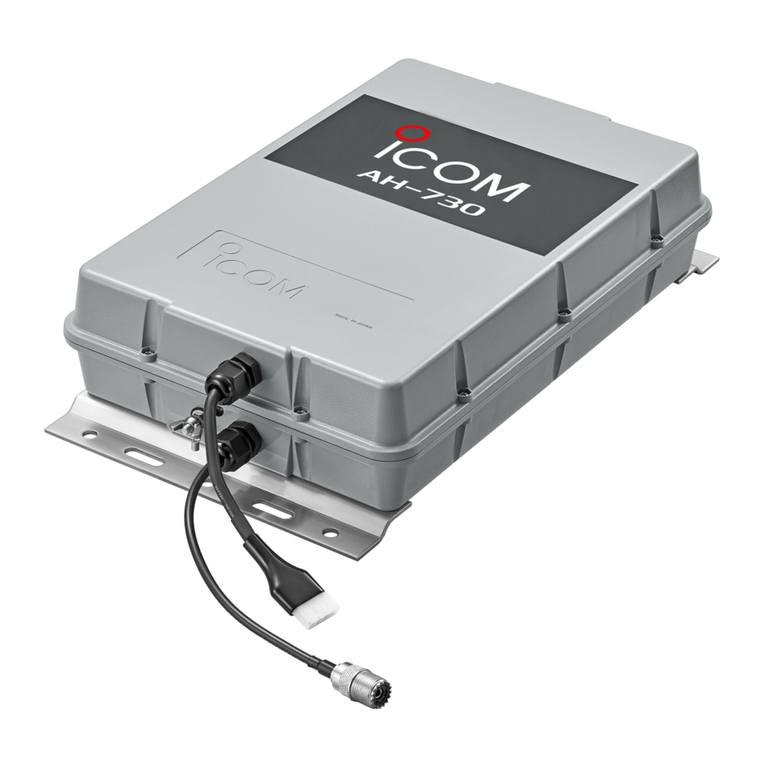
Icom AH-730 User manual

Icom

Icom AH-730 User manual

Icom AT-180 User manual

Icom

Icom AT-180 User manual

Icom AT-141 User manual

Icom

Icom AT-141 User manual

Icom AH-4 User manual

Icom

Icom AH-4 User manual

Icom YPL 880 User manual

Icom

Icom YPL 880 User manual

Icom AT-130 User manual

Icom

Icom AT-130 User manual

Icom AH-2 User manual

Icom

Icom AH-2 User manual

Icom AT-130 User manual

Icom

Icom AT-130 User manual

Icom AT-141 User manual

Icom

Icom AT-141 User manual

Icom AT-140 User manual

Icom

Icom AT-140 User manual

Icom AH-4 User manual

Icom

Icom AH-4 User manual

Icom AT-140 User manual

Icom

Icom AT-140 User manual

Icom AH-3 User manual

Icom

Icom AH-3 User manual

Popular Tuner manuals by other brands

Yamaha Audio TX-1000U owner's manual

Yamaha Audio

Yamaha Audio TX-1000U owner's manual

Bosch DIVAR 2000 Technical notes

Bosch

Bosch DIVAR 2000 Technical notes

Denon TU-580RD manual

Denon

Denon TU-580RD manual

Qwik Tune QT-9 instructions

Qwik Tune

Qwik Tune QT-9 instructions

Pioneer XV-DV830 Service manual

Pioneer

Pioneer XV-DV830 Service manual

Marantz AV8805 owner's manual

Marantz

Marantz AV8805 owner's manual

Technics ST-9030 operating instructions

Technics

Technics ST-9030 operating instructions

Mat-Tuner mAT-705 User instructions

Mat-Tuner

Mat-Tuner mAT-705 User instructions

MFJ MFJ-16010 manual

MFJ

MFJ MFJ-16010 manual

Rotel RT850L owner's manual

Rotel

Rotel RT850L owner's manual

Yamaha YT-100 owner's manual

Yamaha

Yamaha YT-100 owner's manual

Odys SOLO manual

Odys

Odys SOLO manual

Marantz ST-55 user guide

Marantz

Marantz ST-55 user guide

Elan DTNR Installation and user guide

Elan

Elan DTNR Installation and user guide

Palstar AT2K Technical manual

Palstar

Palstar AT2K Technical manual

ZENEC ZE-60MP3 instruction manual

ZENEC

ZENEC ZE-60MP3 instruction manual

DX Engineering DXE-MBV-ATU-1 manual

DX Engineering

DX Engineering DXE-MBV-ATU-1 manual

DirecTV AM21N user guide

DirecTV

DirecTV AM21N user guide

manuals.online logo
manuals.online logoBrands
  • About & Mission
  • Contact us
  • Privacy Policy
  • Terms and Conditions

Copyright 2025 Manuals.Online. All Rights Reserved.