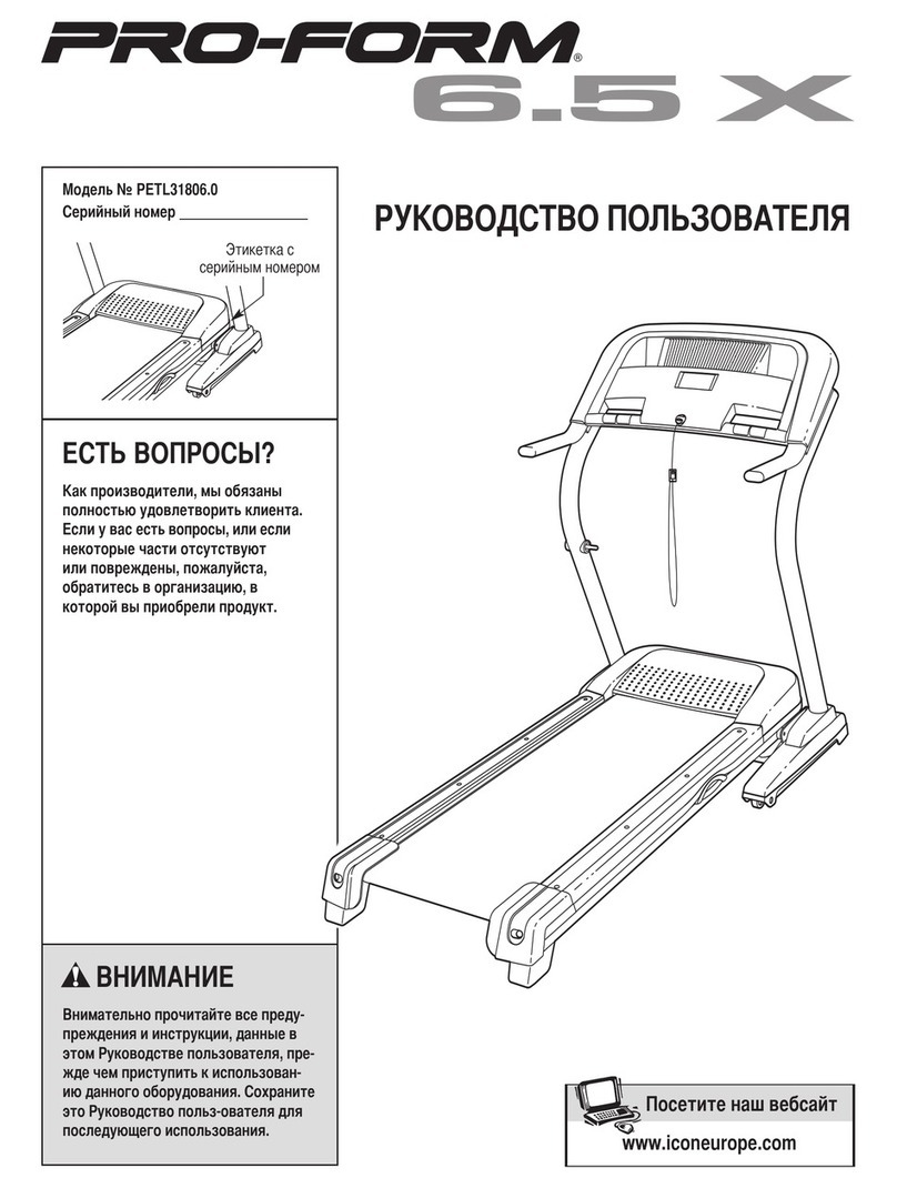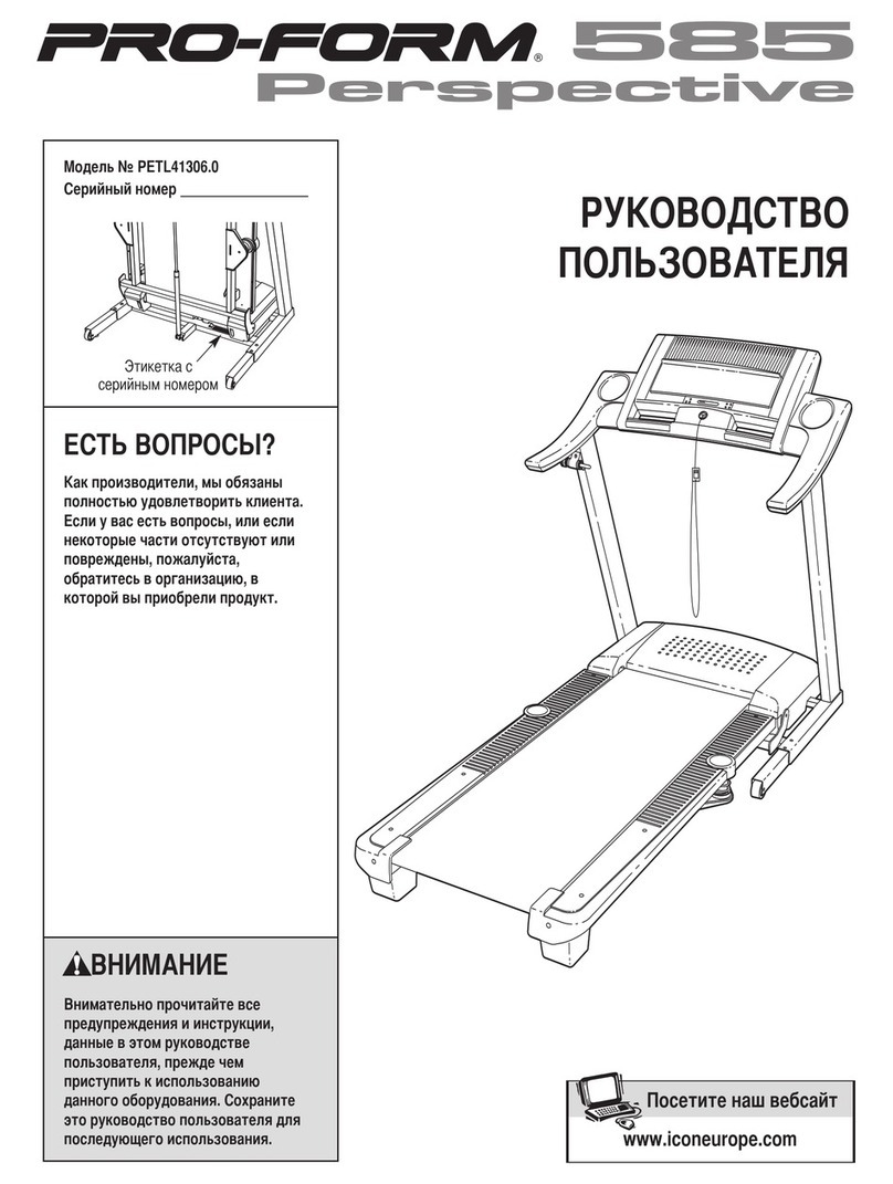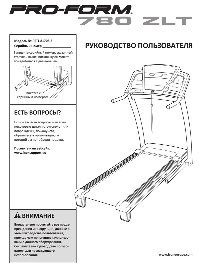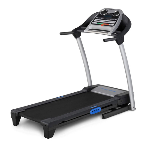
Tread m ill Specifications
>=-,-a?a2
Pi'c:: -': 5 2l
0-10 MPr:
0-10% Power ;: -:
2.5 HP Motor
250 lb. Max. UserWe,g.^:
15 Amp Circuit Breaker
120 VAC 60 Hz
Power Board LEDs
The PB-12i power board has fourtroubleshooting
LEDs to assist the technician when servicing the treadmill.
Not all LEDs are mounted on some power boards. The
meaning of each of these t-If,s rs as .olic'rvs
120V- This LED iignis:: :: :aie:he cc,,,e..:a-l s
receiving 120 VAC. lt viiil iigr.n y,:en :ne treaJa- s
plugged in and the main onioff switch where the po,ver
cord enters the treadmill is tumed on.
+9V- This LED lights to indicate the power board is
generating the g VDC necessary to power the console. lt
must always light when the 120 VAC LED is tit.
P\ AI- This LED monitors the speed control signal being
sent from the console. This signal passes through the
Dov/er board on its way to the motor controller The LED
\rytii begin to fllcxer wnen treaomril speed s set aoove 0.0
ItrlPH and turn off when the treadmill is stopped.
+5V- This LED lights to indicate the power board is
generating the 5 VDC necessary to power the optic
switches. lt must atways tight when the 120 VAi LED is
tit.
Error Code
This console features an Error Code that
when the console fails a self-test.
E6- Checksum Error. This error indicates the console has
failed an internaltest. Unplug the treadmill for 30 seconds
and try again. lf it reappears, replace the console.
MC-60 SCR Motor Controller LEDs
The MC-60 motor controller has four LEDs that can
be used to help troubleshoot electrical problems wjth ihis
treadmill. Each LED, and its meaning, will be described:
D6- Labeted 'SCR.' tt indicates that ihe SCR is triggering
on the controller. lf this light is out, no vottage witt O;
sent to the motor. This LED will vary in brightness
SERVICE HISTORY
SERVICE PERFORMED
Calibration Mode
Th s €.scte has a €libration mode to a$ist the tecrr.:1
rn trcubleshco:inE To entet thrs mode, pre$ and hold the S:.. a^!
Speed l' 5uttons w,hile in-rting the slety key.
The.e are fLve levels to this mode. N4ove from one le,e :.
the next by pre$ ng the Slop button. Exit this mode at any t f,e ./
removing the sfety key
Level 1- This level displays how the @nsole has been @nirg ured to
operate lt als displays the nurerica va ue oi each buttcn as it
is preswd
T VE (Le'1 '/. .t: " ---:.'.'.' ::ii:: :-: :'
T \/tr /t ^-
i rEr1,j .,-=-.J aj:,f,-e:-
SPEED (rei',/,\-ttat-.-* S:e- 'J
SPEED (R19h: %), tra --n lcirne 10
CALS- Roller sae 1 9'
DISTANCE- Soltrere code verspn
Level 2- Th s level is u*d to calibrate the incline and speed of the
treadmill. To calibrate incline, press either /rcloe button. The
treadmill will calibrate itself. To calibrate speed, pre$ and hold
the Speed button until the Distance window displays an 85%
speed signal. Adjust the IMAX SpD pot on the @ntroler until the
Speed Wndow dlsplays 1O O pre$ Speed V and ailowthe
'_::':- :: .':-e': ,::^: o.: 1. "
-',':- _:: _: --<_ :>^as :=-.:
S:::l ::-: s:eea i'iis:-e2.- :-'-! -3 re calib.aiio^
- : - _ 5e 's a(L,e : , --:s :_ 53 .S 3ctve
I S-r'.1= l-rreni pt\4.4 speeo s!^: a H5
-eie :- -. s e!e I ghts each L=D f. ::a --s. e :n crder. The Speed bultc.s
:o.r'ol :he soeel oi.-e r:9nlril.J:e-- -j .E .estartsthe t;ghting
routine and toggles al LEDs on e?a .- -.ilne V laogles matri roft on
and off
Level 4- This level disp ays the tctal i -re 3-6 Drstance of the treadmill. lt also
shov6 the curent units of reasLremeii
T 1,4E, Total t me in hours
SPEED- Unitsr'E'=English,'rn':meiric
CALS- 'd' if Demo mode turned on, e se blank
DISTANCE- Total dlstance in mitE
Level 5- Functional Test. This level allore the treadmill to be t6ted wtlile strll in
calibration mode. The treadmill will run normally after the Slarl button is
presed, but ihe displays willshowdiflerent information.
TIME- Elapsed Tire
SPEED- Speed the tr€dmilt is set to run
DIST - Cutrent PWN4 speed control signal output,O-85,
CALS. act-r' <Fed the t.€o-ill rS.--nrng
depending on the speed setting. lf this LED does not
iight when the safety key is inserted and D7 is lit, the
controller will need to be replaced.
D7- Labeled "SPD CTRL." lt indicates a speed control
signal is being received from the console. The LED
iv:il flicker as the speed signal is received. lf this LED
Jces not light when speed is set above 0.0 MpH, but
D'11 does, it indicates a problem with the speed wires
or console wires.
D'1 1- Labeled "+12V." This LED indicates the controller is
outputting 12 VDC to the speed pot. tf this LED does
not light when voltage is applied, replace the
controller.
D16- Labeled'CUR LtM." This LED tights only rvhen ihe
amperage draw of the treadmill is -:a: .:-e t,_-r-e^:
,,,,,,. >c.i,iiJ. ,;:i,S _=_ ..j,::S:-=que::., : -.::;::S:
wom walking beh or board, or a tight waiking or drive
belt.
Units of Measurement
The units of measurement can be changed
between English and Metric in the User lnformation Mode.
Enterthis mode by pressing down the Sfop button while
inserting the key. The Speed window will display either E
for English or m for metric units of measurement. toggte
between the two settings by pressing the Speed A button.
Demo Mode
The console has a demo built into its software.
The demo mode loops the console dispiay through a
lighting routine when the treadmill is plugged in, but the
key is not inserted. All button presses are disableO.
To disable this mode, enter the User lnformation
mode by pressing down the Sfop button while inserting the
key. The Calories window willdisplay a ,d' if demo mode is
active. Press the Speed V button to toggle the mode on and
off .
