2ATHENA : Embedded
Vortex
86AIO SBC
0.2 Specification for Athena
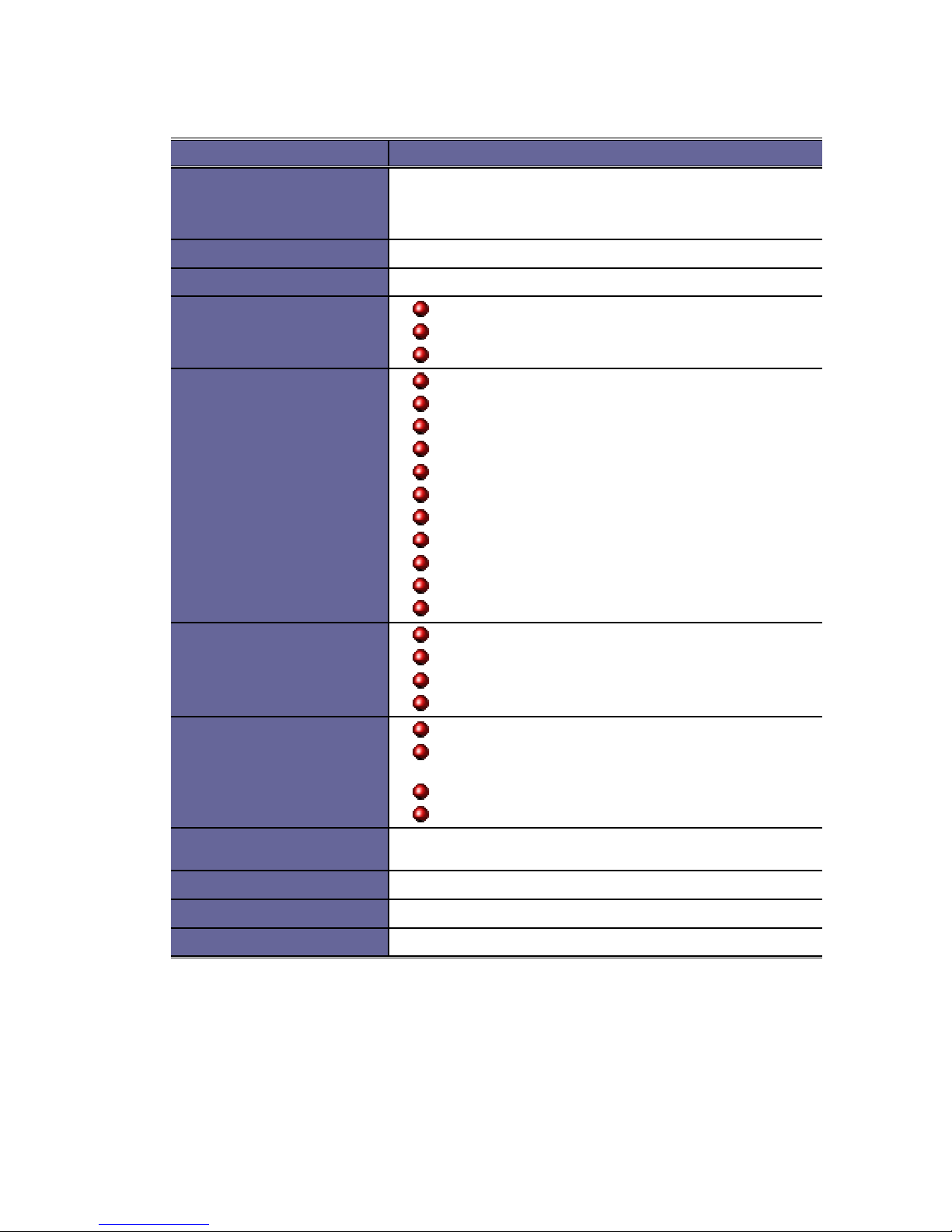
Features ATHENA
SoC DM&P(SiS)Vortex86
System-on-Chip CPU–166MHz
Real Time Clock with Lithium Battery Backup
Watchdog Timer: 30.5uS to 512uS
BIOS AMI BIOS
System Memory 144-pin SODIMM Socket
I/O Interface Enhanced IDE interface x1
Parallel port x1
USB port x3
Connectors External 15-pin D-type female VGA connector
External 25-pin D-type female Printer connector
External RCA Video In/TV Out connector
External Audio connector and Mic-In
External 6-pin Mini DIN for PS/2 Keyboard
External 6-pin Mini DIN for PS/2 Mouse
External RJ-45 connector for 10/100Base-Tx x1
External USB connector x3
External DC Jack for Power Adapter
2.0mm ∅44-pin box header for IDE
2.0mm
∅10-pin box header for RS-232 x1
2.0mm ∅10-pin box header for VGA2
Power push button x1
Video Display AGP Rev.2.0 Compliant
Shared system memory
Resolution up to 1,920x1,440 true colors
CRT display
LAN Realtek 8100B single chip x1
Full-duplex transfer mode, doubles effective
bandwidth
NE2000 compatible with built-in 16KB RAM buffer
Throughput 10/100Mbps
Audio Full compliant with AC97 CODEC v2.1
Internal MIC-in, Line-in and Line-out interface
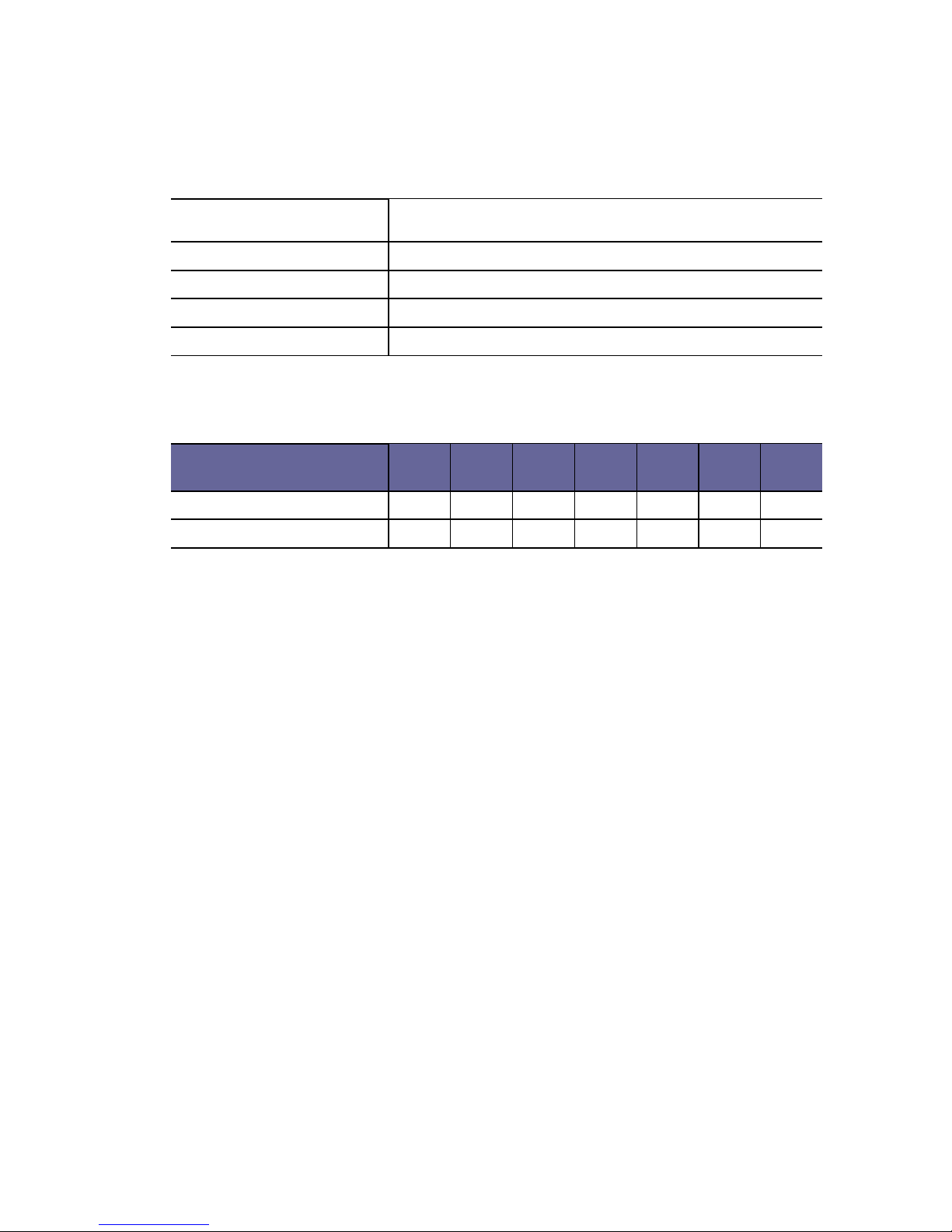
Power Requirement Single Voltage +5V @1.7 A with ACPI function support
(Advanced Configuration and Power Interface)
Board Weight 350g
Board Size 133mm X 111mm (5.23 x 4.37 inches)
Operating Temperature -20oC ~ +60oC