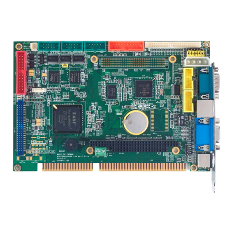
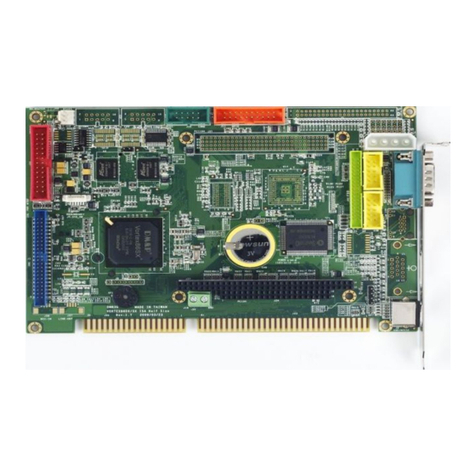
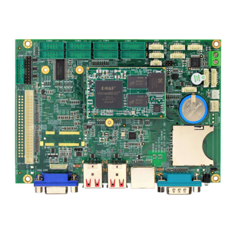
Icop VEX-6225 User manual

User Manual
VEX-6225
with
DM&P Vortex86EX
400MHz processor
Version 3.0

VEX-6225 User Manual
ICOP Technology Inc. I
Copyright
The information in this manual is subject to change without notice for continues
improvement in the product. All rights are reserved. The manufacturer assumes no
reasonability for any inaccuracies that may be contained in this document and
makes no commitment to update or to keep current the information contained in
this manual.
No part of this manual may be reproduced, copied, translated or transmitted, in
whole or in part, in any form or by any means without the prior to written
permission of ICOP Technology Inc.
ⓒ Copyright 2017 ICOP Technology Inc
Trademarks Acknowledgement
Vortex86EXTM is the registered trademark of DM&P Electronics Inc.
Other brand names and product names that appear in this document are the
properties and registered trademarks of their respective owners. All names
mentioned herewith are served for identification purpose only.

VEX-6225 User Manual
ICOP Technology Inc. II
Revision History
Revision Date Remark
1.0 May 22, 2017 First version released
2.0 July 13, 2017 Second version released
3.0 Mar 29, 2017 New add: Pinout for Expansion I/O

VEX-6225 User Manual
ICOP Technology Inc. III
Table of Contents
1 General Information .......................................................................................................................... 1
1.1 Overview ............................................................................................................................................. 1
1.2 Block diagram ..................................................................................................................................... 2
1.3 Specifications ...................................................................................................................................... 4
1.4 Ordering Information ....................................................................................................................... 6
1.4.1 VEX-6225 .................................................................................................................................... 6
1.4.3 SATA DOM ................................................................................................................................ 7
2 Hardware Information ....................................................................................................................... 8
2.1 Dimension ........................................................................................................................................... 8
2.2 Board Outline ................................................................................................................................... 10
2.3 Connector and Jumper Summary ................................................................................................. 11
2.4 Pin Assignments & Jumper Settings ............................................................................................. 12
J3: RS232/485 Switch for COM2 .................................................................................................... 12
J4: SATA DOM .................................................................................................................................. 12
J5: USB1 ............................................................................................................................................... 13
J6: +5V DC Output ........................................................................................................................... 13
J7: USB2 ............................................................................................................................................... 14
J8: Micro SD Slot ................................................................................................................................ 14
J9: CAN ................................................................................................................................................ 15
J10: Mini PCI Express Socket1 ........................................................................................................ 15
J11: SIM Card Slot .............................................................................................................................. 16
J12: Mini PCI Express Socket2 ........................................................................................................ 17
J13: Mini PCI Express Socket3 ........................................................................................................ 18
J14: I2C.................................................................................................................................................. 19
J15: PS/2 Keyboard ........................................................................................................................... 19

VEX-6225 User Manual
ICOP Technology Inc. IV
J16: PS/2 Mouse ................................................................................................................................. 20
J17: ADC .............................................................................................................................................. 21
J18: VGA.............................................................................................................................................. 22
J19: LCD .............................................................................................................................................. 23
J20: LCD Backlight Control ............................................................................................................. 24
J22: Expansion I/O ........................................................................................................................... 25
J24: Power ............................................................................................................................................ 16
J25: LAN .............................................................................................................................................. 16
J26A: COM1 ........................................................................................................................................ 17
J26B: COM2 ........................................................................................................................................ 17
3 Software Resources .......................................................................................................................... 18
3.1 ICOP Technical Resource Website .............................................................................................. 18
Technical Support Directly from ICOP ................................................................................................. 19
User Manual Feedback ............................................................................................................................... 19
Appendix ...................................................................................................................................................... 20
SOM200EX Module: ............................................................................................................................. 20
Design Reference for SOM200EX Module ....................................................................................... 21
Warranty ....................................................................................................................................................... 22

VEX-6225 User Manual
ICOP Technology Inc. 1
1 General Information
1.1 Overview
Based on SOM200EX module with 512MB DDR3 onboard memory,
VEX-6225 offers balanced and stable computing performance for your industrial
applications.
VEX-6225 is equipped with Mini PCIe, USB, COM, SATA, Micro SD, CAN,
I2C, ADC, LCD, VGA, LAN and SIM card slot allowing 3G/4G wireless
communication plus expansion I/O to meet a variety of application demands like
data acquisition, industrial automation, process control, medical device, etc.
Designed to meet 3.5” specification with backward compatibility to provide
migration path for projects facing end-of-life challenges with their existing x86
based 3.5” controller. Additionally, the VEX-6225 family of controller is designed
as plug in replacement with backward compatibility to support legacy software to
extend existing product life cycle without heavy re-engineering.

VEX-6225 User Manual
ICOP Technology Inc. 2
1.2 Block diagram
VEX-6225-43VE
SOM200EX43VGNE1
SOM200EX Carrier Board

VEX-6225 User Manual
ICOP Technology Inc. 3
VEX-6225-43EE
SOM200EX43EGNE1 SOM200EX Carrier Board

VEX-6225 User Manual
ICOP Technology Inc. 4
1.3 Specifications
CPU Vortex86EX 400MHz, L1 I/D-Cache 16/16KB, L2 128KB
RMA 512MB DDR3 Onboard
BIOS Coreboot BIOS
Bus USB-signal 3G/4G modem with Mini PCI Express From Factor x1
Mini PCI Express Socket x2 (Optional)
Expansion I/O x1 (Optional)
(A)USB x3 + 8-bit GPIO x3, or
(B)USB x3 + COM x3, or
(C)USB x3 + Printer x1 + SPI Bus x1
Display Integrated 2D VGA chip with VGA and TFT Flat Panel Interface Support
VGA: Maximum resolution up to 1024 x 768 @60Hz
LCD: Maximum resolution up to 1024 x 768 @60Hz
LAN Integrated 10/100Mbps Ethernet
Disk Support SATA DOM │ Micro SD
I/O Interface 8CH 11-bit ADC x1 │ USB(ver2.0) x2 │ RS232 x1 │ RS232/485 x1
CAN x1 │ I2C x1
Connectors Mini PCI Express Socket x3 │ Micro SD Card Slot x1 │ SIM Card Slot x1
1.25mm 6-pin wafer for I2C x1
2.0mm 56-pin female connector for Expansion I/O x1
2.0mm 10-pin box header for VGA x1
2.0mm 44-pin box header for LCD x1 │ 2.0mm 16-pin header for ADC x1
2.54mm 3-pin molex header for CAN x1
2.54mm 5-pin box header for Keyboard x1
2.54mm 5-pin box header for Mouse x1
2.54mm 2-pin header for RS232/485 switching x1
External D-Sub 9-pin male connector for RS232 x1
External D-Sub 9-pin male connector for RS232/485 x1
External RJ45 connector for Ethernet x1
External Standard USB port x 2 │ 2-pin power terminal connector x1
2-pin box header for +5V DC Output x1
7-pin SATA connector for SATA DOM x1
Power
Requirement +12 – 24VDC Input Typical Consumption: +12VDC Input @ 200mA
Operating
Temperature
-20°C to +70°C
-40°C to +85°C (Optional)

VEX-6225 User Manual
ICOP Technology Inc. 5
Operating
Systems
DOS │ Windows CE6 │ Windows Embedded Compact 7 │ Linux │ QNX
VxWorks │ FreeBSD
Dimension 102 x 146mm (4.01 x 5.75 inches)
Weight 165g

VEX-6225 User Manual
ICOP Technology Inc. 6
1.4 Ordering Information
1.4.1 VEX-6225
PART NO. VEX-6225-43VE VEX-6225-43EE
CPU (MHz) 400MHz 400MHz
DRAM (DDR3) 512MB 512MB
Storage SATA, Micro SD SATA, Micro SD
Display VGA, LCD N/A
LAN 1 1
SIM Card Slot 1 1
USB (ver. 2.0) 2 2
COM* 2 2
CAN 1 1
I2C 1 1
11-bit ADC 1 1
Expansion I/O 1 1
Mini PCIe Socket 1**
1 1
Mini PCIe Socket 2 N/A 1
Mini PCIe Socket 3 N/A 1
*COM2 can be configured as RS232 or RS485
**Mini PCIe Socket 1 is only available for USB-signal 3G/4G modem

VEX-6225 User Manual
ICOP Technology Inc. 7
1.4.3 SATA DOM
Product Name MLC SLC 0°C to +70°C
-40°C to +85°C
SDM-SST-2G-H-M V
V
SDM-SST-4G-H-M V
V
SDM-SST-2G-H-S-X
V V
SDM-SST-4G-H-S-X
V V
SDM-SST-8G-H-S-X
V V
ISATA-8G-H-M V
V
ISATA-16G-H-M V
V
ISATA-32G-H-M V
V
ISATA-8G-H-M-X V
V
ISATA-16G-H-M-X V
V
ISATA-32G-H-M-X V
V
ISATA-1G-H-S
V V
ISATA-2G-H-S
V V
ISATA-4G-H-S
V V
ISATA-8G-H-S
V V
ISATA-16G-H-S
V V
ISATA-16G-H-S-X
V V

VEX-6225 User Manual
ICOP Technology Inc. 8
2 Hardware Information
2.1 Dimension
TOP

VEX-6225 User Manual
ICOP Technology Inc. 9
Bottom

VEX-6225 User Manual
ICOP Technology Inc. 10
2.2 Board Outline
I
2
C (J14)
ADC (J17)
SOM200EX Module
LCD
(J19)
VGA (J18)
CAN (J9)
PS/2 Mouse (J16)
PS/2 Keyboard (J15)
Expansion I/O (J22)
SIM Card Slot (J11)
+5V DC Output (J6)
SATA DOM (J4)
RS232/485
Jumper Switch (J3)
Mini PCIe
Socket 1 (J10)
+12~24V DC Input (24) COM2 (J26B)
LAN (J25)
USB2 (J7)
Reset (S1)
Mini PCIe Socket3 (J13)
Micro SD Card Slot (J8)
Mini
PCI
e
Socket 2 (J12)
USB1 (J5)
COM1 (J26A)
LCD Backlight Control (J20)

VEX-6225 User Manual
ICOP Technology Inc. 11
2.3 Connector and Jumper Summary
Nbr. Name Type of Connections Pi
n of Nbr.
J3 RS232/485 Jumper Switch
for COM2
Pin Header, 2.54mm, 2x1 2
J4 SATA DOM SATA 7P Connector, 7x1 7
J5 USB1 Type A USB connector 4
J6 +5V DC Output Box Header, 2.0mm, 1x2 2
J7 USB2 Type A USB connector 4
J8 Micro SD Slot Standard Micro SD Slot 9
J9 CAN Molex Header, 2.54mm, 1x3 3
J10 Mini PCIe Socket1* Standard Mini PCI Express Connector
52
J11 SIM Card Slot Standard SIM Card Slot 8
J12 Mini PCIe Socket2 Standard Mini PCI Express Connector
52
J13 Mini PCIe Socket3
J14 I2C Wafer, 1.25mm, 1x6 6
J15 PS/2 Keyboard Box Header, 2.54mm, 1x5 5
J16 PS/2 Mouse Box Header, 2.54mm, 1x5 5
J17 ADC Pin Header, 2.0mm, 8x2 16
J18 VGA Box Header, 2.0mm, 5x2 10
J19 LCD Box Header, 2.0mm, 22x2 44
J20 LCD Backlight Control Box Header, 2.54mm, 1x4 4
J22 Expansion I/O Box Header, 2.0mm, 28x2 56
J24 +12 to 24V DC Input Terminal Block, 2x1 2
J25 LAN RJ45 Connector 8
J26A COM1 D-Sub 9-pin male connector 9
J26B COM2** D-Sub 9-pin male connector 9
*Mini PCIe Socket 1 is only available for USB-signal 3G/4G modem
**COM2 can be configured as RS232 or RS485

VEX-6225 User Manual
ICOP Technology Inc. 12
2.4 Pin Assignments & Jumper Settings
J3: RS232/485 Jumper Switch for COM2
2-pin header switch (2.54mm) which used to changing COM2 from RS232 to RS485, and vice
versa.
Pin#
Signal Name
1. GND
2 RS485
OPEN: Enable RS232
CLOSE: Enable RS485
J4: SATA DOM
Standard 7-pin SATA connector for SATA storage. The 7th pin of SATA DOM connector is set
to GND as default. If you would like to have +5V DC power supply from the 7th pin connector,
please contact us at info@icop.com.tw.
Pin#
Signal Name
1. GND
2 TX+
3 TX-
4 GND
5 RX-
6 RX+
7 GND
1
7
1 2

VEX-6225 User Manual
ICOP Technology Inc. 13
J5: USB1
Vertical USB female connector with USB 2.0 support, Type A
Pin#
Signal Name
1. VCC
2 USB_DATA-
3 USB_DATA+
4 GND
J6: +5V DC Output
2-pin box header (2.0mm) for +5V DC output, which is often used be a power supply to SATA
storage.
Pin#
Signal Name
1. VCC
2 GND
1
4
1
2

VEX-6225 User Manual
ICOP Technology Inc. 14
J7: USB2
Vertical USB female connector with USB 2.0 support, Type A
Pin#
Signal Name
1. VCC
2 USB_DATA-
3 USB_DATA+
4 GND
J8: Micro SD Slot
Standard Micro SD slot for Micro SD card
Pin#
Signal Name
1. DAT2
2 DAT3
3 CMD
4 VDD
5 CLK
6 VSS
7 DAT0
8 DAT1
9 Card Detect
1
4
9
1

VEX-6225 User Manual
ICOP Technology Inc. 15
J9: CAN
3-pin molex header (2.54mm) for CAN which supports CAN bus 2.0A/B with data rate up to 1
Mbps.
Pin#
Signal Name
1. CAN_H
2 CAN_L
3 GND
1
3
This manual suits for next models
2
Table of contents
Other Icop Motherboard manuals

Icop
Icop VDX-6300RD User manual

Icop
Icop VSX-6121-FD-V2 Series User manual

Icop
Icop athena User manual

Icop
Icop VORTEX86-6047LV-6S User manual

Icop
Icop VDX-6318 User manual

Icop
Icop VSX-6124-V2 User manual

Icop
Icop VSX-6121-V2 User manual

Icop
Icop NAD11-103-SD User manual

Icop
Icop VDX-6328RD-NF User manual

Icop
Icop VEX2-6427 User manual