ICP Global Pty DIP1000 User manual

1
DIP1000
HDMIwithUSB
Over
IPLAN
(Multi‐castVersion)
InstallationandUser’sManual
ForSalesandServicepleasecontact
ICPGlobalPtyLtd
Phone‐0293142092
Fax‐0293449537
Suite603,Level5,152BunnerongRoad
PAGEOODNSW2035
Date:October4,2011
2
Introduction
TheDIP1000systemisaperfectsolutiontoextendHDMI,USB,andoptional
IR/RS‐232/Remote‐Power‐On‐OffoverIPnetworks.Itincludesthemainunitsof
DIP1000TtransmitterandDIP1000RReceiver,aswellasthebelowmentioned
optionalaccessories.TheDIP1000TtransmitterconnectswithaPCoranyotherdevice
withviaHDMIsource.TheDIP1000RreceiverconnectstoHDMIdisplay,speaker,
microphone,USBdevices(Keyboard/Mouse/Storage/…)andRS232devices.Itisbased
onthestandardEthernetIPnetwork.GigabitorFiberLANswitchescanbeusedfor
inter‐connectionormulti‐casting.
OptionalAccessories:
3.5mmini‐stereotoDB9FemaleRS232controlcable
3.5mmini‐stereotoDB9MaleRS232controlcable
3.5mmini‐stereoto2‐pinsRemotePoweron/offcable
IRblastercable

3
PanelView
DIP1000TTransmitter
No.ComponentDescription
1HDMILoop‐outHDMILoop‐outforLocalMonitor.
2(Button1)
Pressbuttonfor1
secondSwitchvideotoRemoteorLoop‐outmonitor.
Pressbuttonfor>3
seconds
OutputvideotobothRemoteandLoop‐out
monitors.
PressandHoldPowerON
untilGreenandRedLED’s
startblinking
ResetsunittotheFactorydefaultsetting.
2(Button2)
Pressbuttonfor1
secondSwitchtoVideoorGraphicmode
Pressbuttonfor>3
seconds
Anti‐DitherMode.Settingto“Ant i‐Dither
Mode”toachievebettervideoqualityfor
someATIgraphiccards.
PressandHoldPower
ONuntilGreenLED
startsblinking
EstablishesEDIDfromLoop‐outmonitor
3RedLED(System)
4GreenLED
(Power/Link)
GreenBlinking/RedOff:Systemisstartingup.
GreenOn/RedBlinking:WaitingforHDMIinputsource.
GreenOn/RedOn:Connectionestablished.
5RemotePowerConnectstoPCmotherboardforRemotePowerOn/Off.
4
On/Off(optional)
6LinkID
4bitDIPswitchfor16IDsettings.ToenableTransmitter/Receiverasapair
orgroup,thetransmitterandreceivermustbesetwiththesameLinkID.
7GigabitEthernetForconnectingdirectlytoDIP1000RorviaaGigabyteSwitch
8RS‐232Control
(optional)
ProvideSerial‐over‐IPfunction.
9DC5VInSystempowerinput(DC5V2A)
10USB‐to‐PC
ConnectsthisUSB‐BtoPC:
1.USBaudiodevice.(USBaudiodevicewillbedetectedwhenitis
attachedtoPCinWindowsOS)
2.Virtual4‐portUSBHubforremoteUSBdevices.
11HDMIINConnectstoHDMISource.ForDVIsource,youmayneedaHDMI‐to‐DVI
adaptercable.
12IRBlaster
(optional)
ConnectstoexternalIRLED.
PanelView
DIP1000RReceiver

5
No.ComponentDescription
1GreenLED(Power/Link)
2RedLED(Systemstatus)
GreenBlinking/RedOff:Systemisstartingup.
GreenOn/RedBlinking:LinkingorwaitingHDMIinput.
GreenOn/RedOn:Connectionestablished.
3LinkID
4bitDIPswitchfor16IDsettings.ToenableTransmitter/Receiveras
apairorgroup,thetransmitterandreceivermustbesetwiththe
sameLinkID.
4USBHostForremoteUSBdevices,suchasUSBKB/Mouse,storage,audio,…
5IRRx(optional)RemoteUniversalIRreceiver.
6RemotePowerOn/Off
(optional)
ButtonforRemotePCPowerOn/Offfunction.
7Modebutton
Pressbuttonfor1
secondSwitchtoVideoorGraphicmode
Pressbuttonfor>3
seconds
Anti‐DitherMode.Settingto“Ant i‐Dither
Mode”toachievebettervideoqualityfor
someATIgraphiccards.
PressandHoldat
PowerONuntilGreen
LEDblinking
EstablishesEDIDasthesystemEDID
(updateDIP1000TEDID)
8Linkbutton
Pressbuttonfor1
secondLink/Unlink
Pressbuttonfor>3
secondsToenableUSBaccess.
PressandHoldPower
ONuntilGreenand
RedLEDstarts
blinking
ResetsunittotheFactorydefaultsetting.
9DC5VInSystempowerinput5V2A,or4Awhenusedwith4xUSBdevices.
10HDMIOUTConnectstoHDMIdisplay.ForDVIdisplay,youmayneeda
HDMI‐to‐DVIadaptercable.
11RS‐232(optional)ProvidesSerial‐over‐IPfunction.
12Mic.IN
MicrophoneInputfortheUSBaudiodevice.(SettheOSdefault
audiodevicetotheUSBPnPaudiodevicethatiscreatedbythe
DIP1000T)
6
13LineOUT
StereoAudiooutputfortheUSBPnPaudiodevice.(SettheOS
defaultaudiototheUSBPnPaudiodevicethatiscreatedbythe
DIP1000T)
14GigabitEthernetForconnectingdirectlytoDIP1000TorviaaGigabyteSwitch

7
Installation
1. EnsurethattheLink‐IDofboththeDIP1000TandDIP1000Rhavethesame
settings.
2. AttachtheHDMIdisplaytotheDIP1000RHDMI‐Outport.
3. PowerontheDIP1000R.An“AVExtender”logowillbedisplayed.Ifthisdoesnot
appearanerrorhasoccurredwitheithertheDIP1000R,HDMIcableorthe
display.
4. YoucanconnectmultipleDIP1000R’sandmultipleDIP1000TunitstoyourGigabit
Ethernetswitch.AlternativelyuseaCAT6UTPcable(straight,EIA568B)to
directlyconnectaDIP1000TwithaDIP1000Rasapair.
5. AttachtheHDMIsource(PCorBlue‐Ray)totheDIP1000THDMI‐Inportandthen
powerOntheDIP1000T.
6. ThefirstDIP1000RthatisdetectedbytheDIP1000TwillgaintheUSBaccess
right.
7. IfyouareusingyourPCasyourHDMIsource,youwillseeyourHDMIdisplay
EDIDinformationonthePCgraphiccardcontrolpanel.Ifnot,thensomethingis
wrongeitherwiththeDIP1000TorHDMIcable.
8. OutputHDMI(withaudio)fromHDMIsourceandcheckiftheyarecorrectly
displayedonyourHDMIdisplay.
USBoverIPinstallation:
9. ConnectDIP1000TUSB‐to‐PCporttoaWindowsbasedPCUSBportbyaUSB‐A‐B
cable.3deviceswillbedetected:“GenericUSBHub”,“USBCompositeDevice”,
“USBPnPSoundDevice”.
10. Select“USBPnPSoundDevice”astheWindowsdefaultsounddeviceinorderto
usethespeakerandmicrophoneontheDIP1000RLine‐Out(green)and
Microphonejack(pink).
11. AttachUSBdeviceslikekeyboard,mouse,pendrive,audiospeak/microphone…
totheAV‐DIP1000R4USB‐Aports.Note;youwillneedDC5Vwith4Apower
adapterifallDIP1000R4USBportsareused.
12. TogaintheUSBaccessrightamongmultipleDIP1000R,pressandholdformore
than3secsthe“Linkbutton”oftheDIP1000RuntilanOSDmessageof
“RequestingUSB”isdisplayed,thenrelease.AnOSDmessageof“StartingUSB”
willbedisplayedifitsuccessfully.Meanwhile,thepreviousUSBMasterunitwill
showanOSDmessage“USBStopping”.
ResettoFactorydefaultandEDIDOperation
1. ToResettheDIP1000TtotheFactorydefaultsetting:PressandHoldtheButton
1thenPowerONuntilGreenandRedLEDblinking.
8
2. ToUsetheDIP1000TLoop‐outmonitorEDID:PressandHoldtheButtonto
PowerONuntiltheGreenLEDstartsblinking.
3. ToupdatetheDIP1000REDID:PressandHoldtheModebuttontoPowerON
untilGreenLEDisblinking.
4. ToResettheDIP1000RtotheFactorydefaultsetting:PressandHoldtheLink
buttontoPowerONuntilGreenandRedLED’sareblinking.
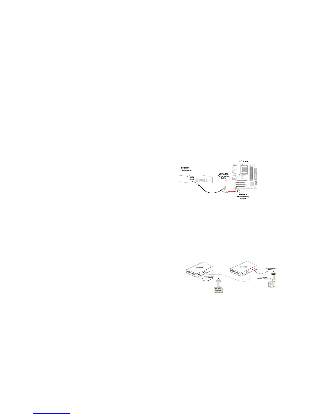
RemotePowerOn/Off(optional)
ThisfunctionisdesignedforremotePoweron/offcontrolofyourPCthroughthe
DIP1000R[RemotePowerOn/Off]pushbutton.
1. Connectthe3.5mmplugofthesuppliedcontrolcableintotheDIP1000T
Transmitter[RemotePoweron/off]socket.
2. Attheotherendofthecontrolcable,thereare2xseparated2‐pinsholders.
ConnectanyonetoyourPCboard[PowerReset]jumper,andtheotherholder
connectstoyourPCResetbuttoncable.
3. OnthefrontpaneloftheDIP1000RReceiver,pressthe[RemotePowerOn/Off]
button.YoucanthenremotePowerOffyourPC.Bypressingthebuttonagain,it
willturnonyourPCagain.
RS‐232Control(optional)
ThisfunctionisdesignedforremoteaccessandcontrolofyourRS‐232device.

9
1. Connectthe3.5mmmini‐stereoplugofthesuppliedRS‐232cabletothe[RS‐232]
socketattherearpaneloftheDIP1000TTransmitter,andthenconnecttheDB9
FemaleconnectorofthesuppliedRS‐232cabletotheCOMportofyourPC.
2. Connectthe3.5mmmini‐stereoplugofthesuppliedRS‐232cabletothe[RS‐232]
socketattherearpaneloftheDIP1000RReceiver,andthenconnecttheDB9
MaleconnectorofthesuppliedRS‐232cabletotheRS‐232device.
RS232PinAssignments
Signal‐NC‐ TxDRxD‐NC‐ ‐NC‐ ‐NC‐‐NC‐‐NC‐‐NC‐
DIP1000R532784619
DIP1000T523876419
InfraredControl(optional)
ThisfunctionisdesignedtotransmitIRsignalfromtheDIP1000RtotheAVsources.
1. ConnectthesuppliedIRblastercabletothe[IRblaster]socketattherearpanel
oftheDIP1000TTransmitter.PleasecheckiftheLEDontheIRblasteriscorrectly
positionedinthefrontoftheAVsources.
2. MakesureyourinfraredremotecontrollerisabletoaligntheDIP1000R[IRRx]
port.Whenyoupressanykeyontheremotecontroller,theDIP1000Rreceives
theIRsignalandtransmitsittotheDIP1000T.ThentheIRsignalisdeliveredto
theAVsourcesdevicethroughtheLEDontheIRblastercable.
3. TheLEDoftheIRblastercablemustbefacingtheIRreceiverofyourWindows
MediaCenterEditionPC,TVtunercardorBlu‐Rayplayer.
Table of contents
Popular Gateway manuals by other brands

ADTRAN
ADTRAN 617600139-13A quick start

SST Automation
SST Automation GT200-BM-RS user manual

Ericsson
Ericsson EDACS Data Advantage Series Installation and Maintenance

Psion Teklogix
Psion Teklogix 9160 G2 user manual

Samson
Samson 5007-2 Series Mounting and operating instructions

Johnson Controls
Johnson Controls Simplicity LINC Application guide