ICS 633GC User manual

F/N 70944 Oct 09 © 2009 ICS, Blount Inc.
633GC / 633F4
OPERATOR’S MANUAL

F/N 70944 Oct 09 © 2009 ICS, Blount Inc.
TITLE633GC / 633F4 OPERATOR’S MANUAL
3
INTRODUCTION / TABLE OF CONTENTS
SYMBOLS & LABELS 4
SAFETY 5
TECHNICAL SPECIFICATIONS 8
SET-UP 9
OPERATION 12
MAINTENANCE 17
TROUBLESHOOTING 25
REFERENCE 26
INTRODUCTION
This manual outlines the maintenance and operation of ICS®manufactured products.
The 633GC / 633F4 chainsaw is designed to cut concrete, stone, and masonry when used with the
appropriate genuine ICS Diamond Chain. Ductile iron pipe may be cut ONLY if using
PowerGritTM Utility Saw Chain.
To get the maximum benefit from your saw, and ensure maximum safety, be sure to read this manual
thoroughly, and periodically review safety instructions.
TABLE OF CONTENTS

© 2009 ICS, Blount Inc. F/N 70944 Oct 09
TITLE 633GC / 633F4 OPERATOR’S MANUAL
4
SYMBOLS & LABELS
THE FOLLOWING SYMBOLS & DEFINITIONS ARE FOUND THROUGHOUT THIS MANUAL AND
ARE DESIGNED TO MAKE YOU AWARE OF POTENTIAL HAZARDS OR UNSAFE PRACTICES.
A potentially hazardous situation exists which, if not avoided,
could result in death or serious injury.
A potentially hazardous situation exists which, if not avoided,
may result in minor or moderate injury or property damage.
A potential situation exists which, if not avoided, may result in
product or property damage.
THE FOLLOWING SYMBOLS & LABELS MAY BE FOUND IN THIS MANUAL OR ON THE SAW
Read the operator’s manual carefully and understand the
contents before you use this equipment.
Always use:
• Protective helmet
• Ear protection
• Protective glasses or full face protection
Wear hand protection
IMPORTANT
WARNING
CAUTION

F/N 70944 Oct 09 © 2009 ICS, Blount Inc.
TITLE633GC / 633F4 OPERATOR’S MANUAL
5
SAFETY
WARNING
THE FOLLOWING SYMBOL APPLIES TO ALL THE ITEMS LISTED ON THIS PAGE
A potentially hazardous situation exists which, if not avoided,
could result in death or serious injury.
Chain breakage can result in high-speed ejection of parts, which can result in death or
serious personal injury to operators or bystanders. The items listed below are critical to
minimizing the risk of chain breakage and injury.
• DO NOT operate a diamond chainsaw with a damaged, modified, broken, or missing side
cover, bottom guard, or guard flap. The side cover, bottom guard, and guard flap provides
protection against contact with moving parts, ejected debris, broken diamond chain,
thrown water and concrete slurry.
• DO NOT operate a saw with loose, missing, damaged or improperly repaired parts.
• DO NOT install or run the chain backwards. The bumper must lead the segment into
the cut.
• DO NOT insert a diamond chainsaw into a slot narrower than the chain segments. Rapid
pushback might occur. Reference: Most diamond segments are .225 inches (5.72 mm)
wide.
• DO NOT use damaged, modified or improperly repaired chain.
• DO NOT run a diamond chainsaw upside-down. Concrete debris can fly back into the
operator’s face.
• NEVER cut ductile iron pipe with the saw (except when using PowerGritTM Utility Saw
Chain). Segment loss or diamond chain breakage may occur.
• See page 16 for information about cutting ductile iron pipe with PowerGrit chain.

© 2009 ICS, Blount Inc. F/N 70944 Oct 09
TITLE 633GC / 633F4 OPERATOR’S MANUAL
6
SAFETY
CAUTION
THE FOLLOWING SYMBOL APPLIES TO ALL ITEMS LISTED ON THIS PAGE
A potentially hazardous situation exists which, if not avoided,
may result in minor or moderate injury or property damage.
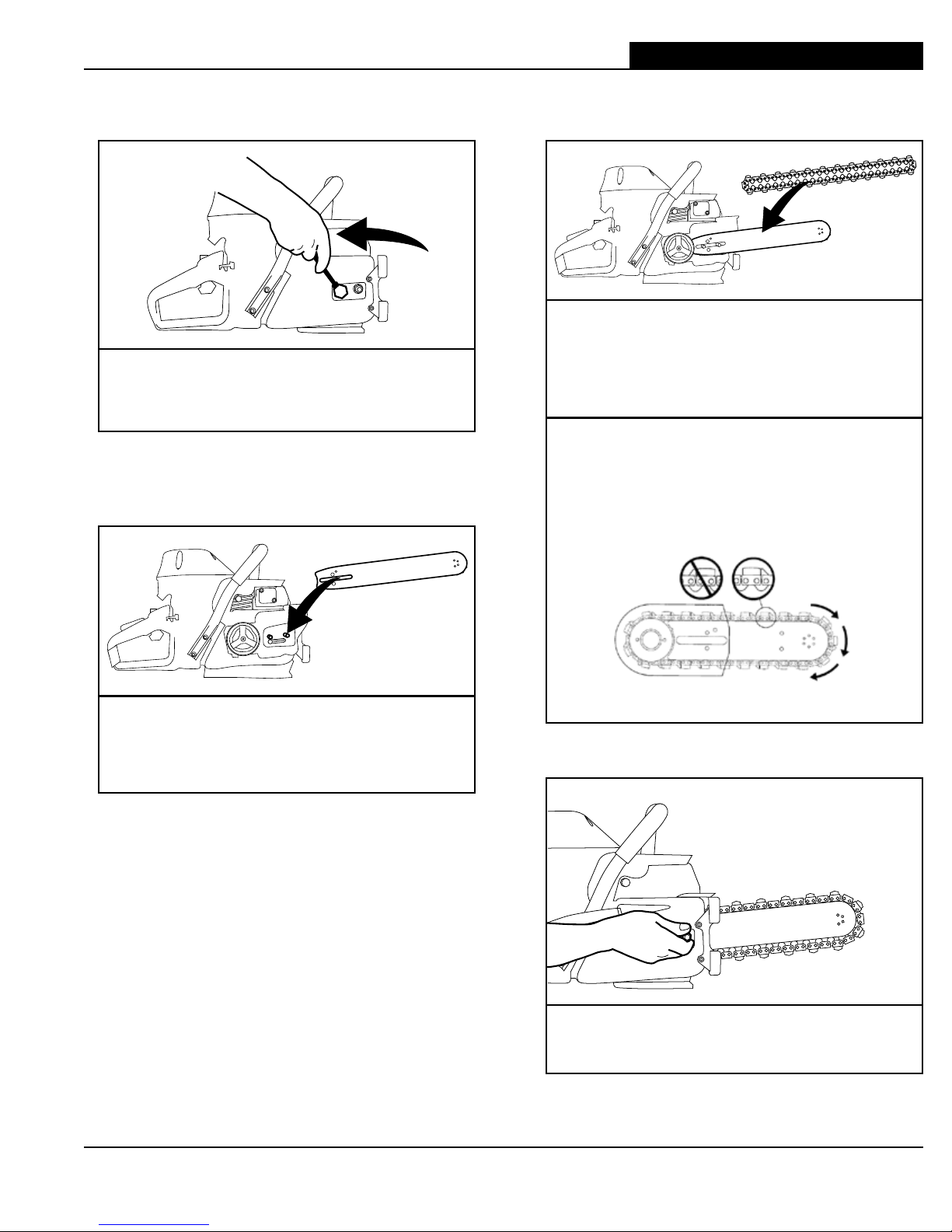
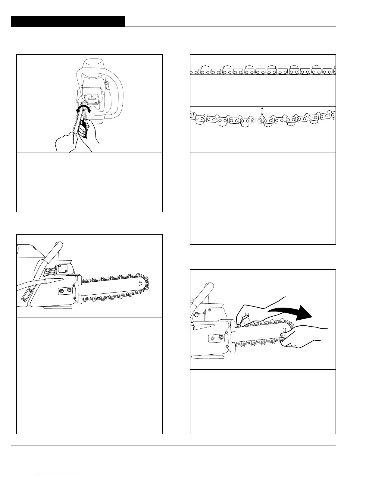
• Always turn a diamond chainsaw OFF when performing maintenance on the saw
including chain tensioning.
• Never use equipment that is not functioning properly. Have the saw repaired by qualified
service personnel.
• Turn engine OFF before refueling. Keep away from open flame. Always provide adequate
ventilation when handling fuel. Move diamond chainsaw at least 10 feet (3 m) away from
refueling area before starting.
• SealPro®diamond chains require a minimum water pressure of 20 psi (1.5 bar).
Insufficient water supply may result in excessive wear to the chain, which can lead to loss
of strength and chain breakage.
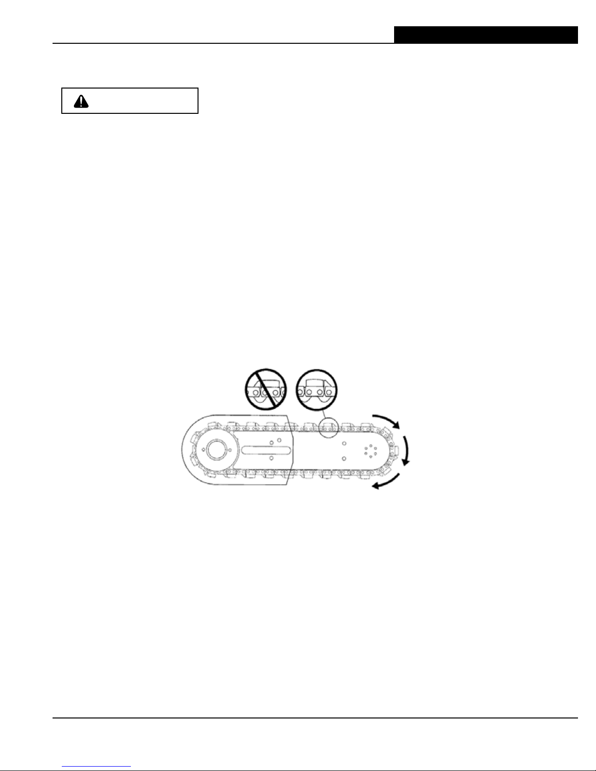
• Never start a diamond chainsaw unless the bar, chain and
side cover are properly installed.
GENERAL SAFETY PRECAUTIONS
• Alwayswearprotectiveclothing,includinghardhat,eyeprotection,hearingprotection,and
gloves.
• Avoidloosefittingclothing.
• Performsafetychecksbeforestartingeachday.
• Alwaysoperatetoolwithsolidfootingandwithbothhandsonsaw.
• Removeorcontrolslurrytopreventslipperyconditionswhilecutting.
• Besuretherearenoobstructions(plumbing,electricalconduit,airducts)andnounnecessary
people present.
• Setupawell-markedsafetyzonewitharopedboundaryandclearsigns.
• Provideadequateventilationwhenworkinginanenclosedarea.Breathingexhaustgasesis
dangerous.
• Toavoidelectrocution,checkforliveelectricalwiringnearcuttingarea.

F/N 70944 Oct 09 © 2009 ICS, Blount Inc.
TITLE633GC / 633F4 OPERATOR’S MANUAL
7
SAFETY
IMPORTANT
THE FOLLOWING SYMBOL APPLIES TO ALL ITEMS LISTED ON THIS PAGE
A potential situation exists which, if not avoided, may result in
product or property damage.
Note: The diamond chainsaw is equipped with a two-stroke engine and must always be
run using a mixture of gasoline and ICS®two-stroke engine oil. It is important to accurately
measure the amount of oil to be mixed to ensure that correct mixture is obtained. When
mixing small amounts of fuel, even small inaccuracies can drastically affect the ratio of the
mixture.
ENGINE BREAK-IN
• It is very important to break-in a new engine to “seat” all moving parts, especially the
piston rings.
• To break-in the engine, run one full tank of 25:1 fuel at idle, cycling the throttle every
5 to 10 minutes to prevent loading.
• Failure to break-in an engine may result in piston seizure.
• This engine is designed to be operated on premium unleaded gasoline.
• Use high quality, unleaded gasoline with a minimum octane rating of 90. If lower octane
gasoline is used, engine temperature will increase which will result in a piston seizure
and damage to the engine.
• Fuel mixture: 25:1 gasoline/oil mixture. Incorrect fuel mixture is the number one cause of
piston seizure.
• Use ICS®brand two-stroke engine oil, or other high quality 2-stroke oil that has been
formulated for air cooled power equipment.
• Never use two-stroke oil formulated for water-cooled two-cycle engines, such as
outboard motor oil.
• Never use motor oil intended for four-stroke engines.

© 2009 ICS, Blount Inc. F/N 70944 Oct 09
TITLE 633GC / 633F4 OPERATOR’S MANUAL
8
TECHNICAL SPECIFICATIONS
Engine Type 2-stroke,AirCooled
Displacement 101cc(6.2cuin)
Horsepower 6.5HP(4.8kw)@8700RPM
Engine Speed 11,500+/-500RPM,Mechanically
governed
Diamond Chain Speed 4,950fpm(25m/s),freerunning
Idling Speed 2800-3200RPM
Weight 27.5lbs(12.5kg)withguidebarand
diamond chain
Cut Depth 14in(36cm)&16.2in(41cm)
Bar Lengths 14in(36cm)&16.2in(41cm)
Carburetor WalbroWGAK3,Throttleshaftsealed,
Ignition Selettra electronic – Water resistant
Clutch Centrifugal, three shoe, single spring
Fuel ratio 25:1gasoline-to-oil
Fuel Capacity 0.26gallon(1liter)
12-15minutesruntimepertank
Water Supply Minimum20psi(1.5bar)
Water Flow Minimum:2gpm(8lpm)
Noise Level 102dBat3ft(1m)
Vibration Level 8 meters/sec2(fronthandle)
EngineBreak-inPeriod Onetank,withoutcutting,cycling
throttle
SparkPlug Champion CJ7Y or Bosch BWS7F

F/N 70944 Oct 09 © 2009 ICS, Blount Inc.
TITLE633GC / 633F4 OPERATOR’S MANUAL
9
SET-UP
STEP 1
Loosen side cover nuts and remove side
cover.
GUIDE BAR AND DIAMOND CHAIN INSTALLATION
STEP 3
Mount the diamond chain on the guide bar
startingatthedrivesprocketandcontinue
over the guide bar nose.
Install the diamond chain correctly.
If using a single bumper chain, the
bumper must always lead the segment
into the cut as shown here.
STEP 4
Install the side cover.
STEP 2
Place bar onto studs and chain adjustment
pin.

© 2009 ICS, Blount Inc. F/N 70944 Oct 09
TITLE 633GC / 633F4 OPERATOR’S MANUAL
10
SET-UP
GUIDE BAR AND DIAMOND CHAIN INSTALLATION
STEP 7
Allchainshaveatendencytostretch
when used. Diamond chains stretch more
than wood cutting chains because of the
abrasive materials they are cutting. When
a chain stretches to a point where the drive
linksarehangingapproximately1/2”
(12mm)to3/4”(18mm)**belowthebar,
it’s time to tension the chain. See Note 2.
STEP 6
If the chain is too loose, it could come off
thebar,oritwillallowthedrivesprocketto
spin without turning the chain, which can
chewupthechaindrivelinks.Ifthechain
is too tight, a lot of the saw’s power goes
into turning the chain rather than into the
cut.Inextremeover-tightenedcases,the
saw may not be able to turn the chain at
all. In addition, damage can occur to the
bar nose and premature stretch may occur.
See Note 1.
STEP 8
Beforecutting,checkforpropertensionby
pulling the chain around the bar by hand. If
you cannot easily pull by hand, the chain is
too tight and needs to be loosened a little.
See Note 3.
** As measured without pulling
downward (eg. hanging by gravity)
3/4" (18 mm)**
STEP 5
Makesureallthedrivelinksareinside
the guide bar groove then lift the bar nose
and tension the chain by turning the screw
clockwise.

F/N 70944 Oct 09 © 2009 ICS, Blount Inc.
TITLE633GC / 633F4 OPERATOR’S MANUAL
11
SET-UP
Note 1: Be aware that the guide bar rails may develop sharp edges over time so always pull the
diamond chain by the diamond segments.
Note2:Donot“overtension”thediamondchain.Lossofpowerwillresult.Itisnormalforthe
drivelinkstohangunderneaththeguidebar.Thediamondchainshouldbetightbutbeabletobe
pulled around the guide bar by hand.
Note3:Topreventchaintensionerbreakage,besurethesidecovernutsaretightenedto
approximately20ft-lbs(27Nm).
GUIDE BAR AND DIAMOND CHAIN INSTALLATION
STEP 9
Continue to lift up on the nose of the guide
bar and firmly tighten the side cover nuts.
NOTE: To prevent chain tensioner
breakage,besurethesidecovernuts
aretightenedtoapproximately20ft-lbs
(27Nm).
STEP 10
Attachtowatersourcewithpressureofnot
lessthan20psi(1.5bar).

© 2009 ICS, Blount Inc. F/N 70944 Oct 09
TITLE 633GC / 633F4 OPERATOR’S MANUAL
12
CAUTION
FUEL HANDLING
FUEL MIXTURE: 25:1 gasoline/oil mixture.
GASOLINE OIL
US
Gallon
US
Floz
1 5.2
2 1/2 12.8
5 25.6
GASOLINE OIL
Liters ml
1 40
5 200
10 400
20 800
• Usepremiumunleadedgasolinewithaminimumoctaneratingof90.Ifloweroctanegasolineis
used,enginetemperaturewillincreasewhichcanresultinapistonseizureanddamagetothe
engine.
• Alwaysprovideadequateventilationwhenhandlingfuel.
• Usecautionwhenhandlinggasoline.Avoiddirectcontactwithskinorinhalingfuelvapor.
FUEL MIXING
• Alwaysmixgasolineandoilinacleancontainerintendedforusewithfuel.
• Keepfuelcontainerclosedtightlytopreventmoisturefromgettingintothefuel.
• Alwaysbeginmixingfuelbyaddinghalftheamountofgasolinetobeused.Thenaddthecorrect
amountoftwo-strokeoilfor25:1mixtureandfinishfillingthecontainerwithgasoline.
• Donotmixmorethanonemonth’ssupplyoffuel.Thishelpspreventtheseparationofthe
two-strokeoilfromthegasoline(varnishing).
• Ifthesawisnotusedforanextendedperiodoftime(3months)thefueltankshouldbeemptied
and cleaned.
FUELING
• Alwaysshutoffthesawbeforefueling.
• Beforefueling,cleantheareaaroundfuelcaptopreventdirtfromcontaminatingthefuel.
Contaminationofthefueltankcanleadtosawmalfunction.
• Thoroughlymixthefuelinit’scontainerbeforefueling.
• Slowlyopenthefuelcaptoreleaseanypressurethatmayhavebuilt-upinthetank.
• Afteraddingfuel,tightenthefuelcapcarefullyandsecurewithawrench.
OPER ATION

F/N 70944 Oct 09 © 2009 ICS, Blount Inc.
TITLE633GC / 633F4 OPERATOR’S MANUAL
13
COLD ENGINE STARTING PROCEDURE
1. Toggletheignitionswitchtothe"START"positionandpullthe
chokeleverout.
2. Lockthethrottleinthestartpositionbydepressingthetrigger(A)
andtriggerinterlock(B)atthesametime.
3. Depressandholdthrottlelockbutton(C)whilereleasingthetrigger
andtriggerinterlockinsuccession.
4. Open the water valve 1/4 turn.
5. Placethediamondchainsawonthegroundmakingsurethechain
is free of any obstructions.
6. Place right foot on the base of the rear handle.
7. Place left hand on front handle.
8. With right hand, slowly pull starter handle until the starter pawls engage.
9. Pullthestartercord(hard, fast, short pulls)untilenginefiresor"pops"-shouldbe1to7pulls.
10.Pushthechokeleverin.
11. Pullthestartercorduntilenginestarts-shouldbe1to2pulls.
12. When the engine starts, allow the engine to idle. Pull on the throttle trigger several times to help
warm up the engine.
13. Open the water valve completely.
CAUTION
STARTING AND STOPPING A DIAMOND CHAINSAW
Never start a diamond saw without the bar, chain and side cover
properly assembled. Otherwise, the clutch can come loose and
cause personal injuries.
Always move a diamond chainsaw at least 10 feet (3 m) away from
the fueling area before starting.
Place the diamond saw on clear ground. Ensure that secure
footing is established and chain is not contacting any objects.
IMPORTANT
WARNING
WARM ENGINE STARTING PROCEDURE
1. Use the same procedure as starting cold engine, but DO NOT pull choke lever out.Ifchokeisused,the
carburetor will flood with gas.
2. Iftheenginedoesnotstartin3hard,fastpullswiththethrottlelocked,unlockthethrottleandpullthe
starter cord 3 more times.
Note: To hold the trigger fully open it may be necessary to insert right foot into rear handle opening
and twist.
Figure1:a-Trigger,b-trigger
interlock,c-throttlelock
CB
A
STOPPING THE SAW
• Toturntheengineoff,toggleignitionswitchtothe"STOP"position.Closewatervalve.
OPER ATION

© 2009 ICS, Blount Inc. F/N 70944 Oct 09
TITLE 633GC / 633F4 OPERATOR’S MANUAL
14
PRE-CUT CHECKLIST
• ProperChainInstallation:Thebumpershouldleadthesegmentintothecut,doublebumper
chains may be mounted in either direction.
• ProperChainTension:Thechainshouldbetightbuteasilypulledaroundtheguidebarbyhand.
• Ensureallsafetydevicesareproperlymountedandfunctionalandthatallcontrolsareinproper
workingorder.
• Besuretherearenoobstructions(plumbing,electricalconduit,airducts)andnounnecessary
people present.
• Alwayswearprotectiveclothing,includinghardhat,eyeprotection,hearingprotection,non-slip
safetyboots,andgloves.Avoidwearingloosefittingclothing.
• AdequateWaterSupplyandPressure:
MinimumFlow:2gpm(8lpm)
MinimumWaterPressure:20psi(1.5bar)
• DiamondchainswithSealPro®requireaminimum
waterpressureof20psi(1.5bar).
PLANNING THE CUT
• Selecttheproperchaintypeforthematerialbeingcut.
• Outlinethecutwithapermanentmarkerforavisualcuttingguide.
• Avoidpinchingtheguidebarandchain.Alwayscutthebottomofanopeningfirst,thentop,and
then the sides. Save the easiest cut for last.
• Forthestraightestcutsusethe“StepCut”method.Firstscoretheentirecutlineapproximatelya
half-inchdeepusingthenoseofthebar.Next,deepenthecutbyabouttwoinches.Thenplunge
allthewaythroughandcompletethecutusingtheWallwalker®.
• Besurecutconcretecannotfallandinjureoperatororbystanders.Concreteisveryheavy,
onecubicfoot=12”x12”x12”=150lbs.(30cmx30cmx30cm=68kg).
• Checkforliveelectricalwiringnearthecuttingareaorintheconcretetoavoidelectrocution.
The single most important factor an operator can control to
increase chain life is to use adequate water pressure. Insufficient
water supply will result in excessive wear to the chain, which can
lead to loss of strength and chain breakage.
IMPORTANT
OPER ATION

F/N 70944 Oct 09 © 2009 ICS, Blount Inc.
TITLE633GC / 633F4 OPERATOR’S MANUAL
15
CUTTING WITH THE 633GC
To start a cut, hold trigger on full throttle and slowly plunge the nose of the bar straight into the wall.
LengthenthecutandengagethepointofthefixedWallwalker®.UsethefixedWallwalker®as a pivot
point and pull up on the rear handle to rotate the bar into the cut.
CUTTING TIPS
• Alwaysoperatethediamondchainsawatfullthrottle.Applyenoughfeedforcesothatthefree
runningRPMdrops20to30%.Iftoomuchforceisapplied,thesawwilllugorstall.Thechainwill
nothaveenoughspeedtocuteffectively.Iftoolittlefeedforceisapplied,thediamondswillskid
andglazeover.
• Forstraightercutsusethe“stepcut”method.Firstscoretheentirecutlinewiththenoseofthe
guidebarapproximately1/2inch(12mm)to1inch(25mm)deep.Next,deepenthecutbyabout
2inches(50mm).Thisgroovewillhelpguidetheguidebarforastraightcut.Thenplungeallthe
waythroughandcompletethecutusingthefixedWallwalker®.
• Plungecutinsteadofstartingatthetopofthewall.Thiswillreducechatter,extenddiamondlife,
createastraightercutandmorequicklyenabletheuseoftheWallwalker®.
• UsethefixedWallwalker®to help cut more efficiently
andreduceoperatorfatigue.ThefixedWallwalker®is
a fulcrum that can be used to apply additional force
when cutting. To use correctly, plunge into the wall
andsimplyengagethepointofthefixedWallwalker®
into the cut and pry upward with the rear handle.
• Asthesawbeginstorotateup,feedforceisdeveloped
down the line of the intended cut. Once the saw is fully
rotated upwards, pull the saw out of the cut a few inches
andre-engagethepickintothecutandrepeat.
• Whencuttingheavyrebar,slowly”rock”thesawsothatyou’realwayscuttingconcreteaswell
assteel.Thiswillhelpkeepthediamondsexposed.Also,expectlesschainlifewhencutting
heavy rebar.
• Expectmorechainstretchwhenmakingnoseburiedcutsforextendedperiodsoftime,asthe
chaindoesnothaveachanceto“throw”theslurryawayfromthenoseofthebar.
• Ifthesawbeginstocutconsistentlycrooked,turnthebaroverandusetheotherside.Dress
worn rails with belt sander. Note: The normal life of a guide bar is 2 to 3 diamond chains. Heavy
rebar can shorten guide bar life.
• Whenusinganewchain,youcanincreasethecuttingspeedby“openingupthediamonds”.
Makeafewcutsinanabrasivematerialsuchasacinderblock.
WallWalker®point
OPER ATION

© 2009 ICS, Blount Inc. F/N 70944 Oct 09
TITLE 633GC / 633F4 OPERATOR’S MANUAL
16
OPER ATION
SYSTEM CLEAN-UP
• Aftercutting,runthesawforatleast15secondswiththewaterontoflushslurryanddebrisfrom
chain,baranddrivesprocket.
• Washconcreteslurryfromsawassembly.
• Avoidgettinganywaterinthecarburetororexhaustsystem.Ifwaterentersexhaustport,point
the bar tip down and pull the starter handle several times to expel water from muffler.
• Removebarandchain.Flushoutthechaintensionerandsidecoverwithwater.Lubricate
tensioner with grease.
• Aftercleaningthesaw,spraytheentiresawbody,chain,bar,anddrivesprocketwithlightweight
oil.Usinglightweightoilonthesawwillminimizerustandhelpreduceslurrybuildup.
CUTTING DUCTILE IRON PIPE WITH THE POWERGRITTM UTILITY SAW CHAIN
NEVER cut ductile iron pipe with the saw unless using PowerGrit Utility Saw Chain. The following
are safety precautions that should always be followed when using PowerGrit.
• Before cutting, make sure the pipe is in a safe condition to
be cut. Support the work piece in such a way that the cut
remains open during the cutting operation and when the cut is
finished. Pinching the chain during the cut could cause chain
breakage and could result in death or serious injury to the
operator.
• If using the pipe clamp accessory, the clamp must be
attached in such a way that it does not move during the
cutting operation and/or when the cut is finished. Unexpected
movement of the clamp could cause loss of control of the saw
and could result in death or serious injury to the operator.
WARNING

F/N 70944 Oct 09 © 2009 ICS, Blount Inc.
TITLE633GC / 633F4 OPERATOR’S MANUAL
17
MAINTENANCE
Follow these simple maintenance guidelines
and the 633GC Concrete Cutting Saw will keep running at its very best.
AFTER EACH USE
1. Rinsethesaw,guidebaranddiamondchainwithwater.
2. Follow instructions on the Daily Maintenance Label, located on the air filter cover.
3. Inspect and tighten all fasteners as necessary.
4. Inspectdrivesprocketfortoothwearandreplaceiftoothtipsarepointed.
5. Inspectthestartercord.Replaceiffrayed.
6. Cleanairfilter.Inspecttheairfilterforholes.Replaceasnecessary.
7. Spray saw, guide bar, and chain with lightweight oil.
8. Grease the chain tensioner.
AFTER 10 HOURS OF USE
1. Removethestartercoverandlubricatethestarterrecoilspring.Cleantheflywheelfinsandthe
starter pawls with a wire brush, then grease the starter pawls.
2. Removethesparkplugandcleanwithawirebrush.Checktheelectrodegap.
Thecorrectgapis0.020inches(0.5mm).
AFTER 40 HOURS OF USE
1. Changethesparkplug.Adjusttheelectrodeto0.020inches(0.5mm).
2. Checkthefuelfilterlocatedinsidethefueltank.Cleanorreplaceifclogged

© 2009 ICS, Blount Inc. F/N 70944 Oct 09
TITLE 633GC / 633F4 OPERATOR’S MANUAL
18
AIR FILTER
The air filter is made from a nylon micro mesh air filter and an
internal spit-back screen. Both must be kept clean for the engine
to operate properly. If the saw is not reaching full RPM, most
likely one or both of the air filters are dirty.
IMPORTANT
• Theairfilter(Figure1)shouldbefreeofholesandwhitein
color.
• Replaceairfilterwhendirty.
• Thespit-backscreen(Figure2)shouldbefreeofholesandbe
white in color. Clean with mild solvent or gasoline and dry with
highpressureair.Ifspit-backscreenisdirtythesawwillnot
reachfullRPM.
• Duringre-assembly,tightenairfilterwing-nut"fingertight"plus
an 1/8" of a turn with wrench.
STARTER HOUSING ASSEMBLY
It is common for concrete slurry to get inside the starter housing
assembly during cutting. This can cause the starter pawls to stick
and not engage when the rope is pulled.
IMPORTANT
• Aftereachusage,thoroughlyflushthestarterhousing
assembly with water.
• Oiltherecoilspringbysprayinglightweightoilintotheport
(Figure3).
• Oilthestarterpawlsbysprayinglightweightoilintothestarter
housing through the vents.
• Checkthestartercordforfraying,replaceifnecessary.
Figure 1
Figure 3
Figure 2
MAINTENANCE
Oil port

F/N 70944 Oct 09 © 2009 ICS, Blount Inc.
TITLE633GC / 633F4 OPERATOR’S MANUAL
19
• Removethefourscrewsattachingthestarterassemblytothe
crankcase,andremovethestartercoverassembly.
• Removethethreestarterpulleycoverscrews.
• Removethestarterpulleycover.
• Pulltheropeoutuntilthenotchinthepulleyhasmadeatleast
two full revolutions and is at the rope inlet, then hold the pulley
inplace(Figure1).
• Whileholdingthepulleyinplace,lifttheropeintothepulley
notchandallowthepulleytounwindslowly(counterclockwise)
withoutwrappingtherope(Figure2).Dothisuntiltherecoilspringiscompletelyunwound.
• Undothescrewinthecenterofthepulley,andremovethepulley.
• Removetheoldropefromthepulley.Retainthestarterropewasher.
• Prythestarterroperetainerfromthestarterropehandle,andremovetheoldropefrom
the handle.
• Tieaknotinoneendoftheropeandthreadtheropethroughthe:
o Starter rope washer, then
o Starter rope pulley, then
o Starter cover, then
o Starter rope handle, then
o Starter rope retainer
• Tieaknottolocktheendoftheropeinthestarterrope
retainer.
• Reseatthestarterroperetainerinthestarterropehandle.
• Replacethepulleyinthestartercover.UseblueLoctite#242
on the starter pulley screw.
TENSIONING THE RECOIL SPRING
Figure 2
STARTER ROPE REPLACEMENT
Figure 1
MAINTENANCE
• Withtheropefullyextendedandnotensionontherecoilspring,lifttheropeintothenotchinthe
pulleyandrotatethepulleyclockwise7wraps(Figure2),andthenallowthespringtoretractthe
rope.
• Thisshouldapplytheproperamountoftensiontotherecoilspring.
• Ifthepulleyisover-wrapped,therecoilspringwillbreakonuse.Tocheckthatthestarterpulley
isnotover-wrapped,pullthecordcompletelyoutofthehousing,andturnthepulleyanadditional
1/2turnclockwise.Ifthepulleyturnsanother½turn,itiscorrectlyassembled.Ifnot,releaseone
wrapofropeandcheckagain.

© 2009 ICS, Blount Inc. F/N 70944 Oct 09
TITLE 633GC / 633F4 OPERATOR’S MANUAL
20
CHAIN TENSIONER
The chain tensioner (Figure 2) can become clogged with concrete
slurry during cutting. After each use thoroughly flush the chain
tensioner with water and apply a liberal amount of grease.
IMPORTANT
Most Common Causes of Tensioner Damage:
• Sidecovernutsarenottightenough.Sidecovernutsshould
betorquedto20ft-lbs(27Nm).
• Chaintensioningisattemptedwithoutlooseningthesidecover
nuts.
• Concretedebrisintensionerpocket.
Figure 2
Chain
Tensioner
MAINTENANCE
STARTER HOUSING ASSEMBLY
• Toreattachthestarterhousing,firstpullthestartercordout,
thenholdthestarterhousingagainstthecrankcase(Figure1).
Slowly release the starter cord to enable the pulley to fit
between the pawls.
• Insertandtightenthescrews.UseblueLoctite®#242.
Figure 1

F/N 70944 Oct 09 © 2009 ICS, Blount Inc.
TITLE633GC / 633F4 OPERATOR’S MANUAL
21
DRIVE SPROCKET
The drive sprocket (rim sprocket) is a wear item and should be
replaced every 2-3 diamond chains.
IMPORTANT
The needle bearing inside the splined adapter should be greased
regularly and should be replaced with each new clutch cup.
IMPORTANT
Arimsprocketsystem(Figure1)consistsofaclutchcup
w/splinedadapterandarimsprocket.Whentherimsprocket
wears out, it is the only part that needs to be replaced. The clutch
cup with splined adapter is a wear item that needs replacement
after3to5rimsprocketshavebeenused.
• Inspecttherimsprocketforwear.Replacetherimsprocketif
the drive teeth become pointed.
• Checkthedrivesprocketbearingbyspinningclutchcup.
Replacethebearingifitiswornout.
• Theneedlebearingonthedriveshaftmustbegreased
regularly,usehighqualitywater-resistantbearinggrease.
Figure 1
Clutch
Cup
Splined
Adapter
Rim
Sprocket
DRIVE SPROCKET REMOVAL
• Removethesidecover,guidebar,diamondchain,andclutch
slurry shield.
• Removethesparkplugandinsertthepistonstop(supplied
witheachsaw)intothesparkplughole.Pullthestartercord
slowlyuntilthepistonstops.(Figure2)Usea19mmwrenchto
turntheclutchclockwiseandremove.
• Slidetheclutchcup/drivesprocketassemblyofftheshaft.
Removetheneedlebearingandinspectforheavywearor
damage.
Figure 2
MAINTENANCE
Other manuals for 633GC
3
This manual suits for next models
1
Table of contents
Other ICS Chainsaw manuals