ICS 880 Hydraulic Saw User manual

© 2007 ICS, Blount Inc. F/N 525665 Oct 07
880 Hydraulic Saw
OPERATOR’S MANUAL


TITLE
880 OPERATOR’S MANUAL
3
F/N 525665 Oct 07 © 2007 ICS, Blount Inc.
TABLE OF CONTENTS
SYMBOLS & LABELS 4
SAFETY 5
TECHNICAL SPECIFICATIONS 7
SET-UP 8
OPERATION 10
MAINTENANCE 12
TROUBLESHOOTING 14
REFERENCE 15

880 OPERATOR’S MANUAL
4© 2007 ICS, Blount Inc. F/N 525665 Oct 07
SYMBOLS & LABELS
THE FOLLOWING SYMBOLS & DEFINITIONS ARE FOUND THROUGHOUT THIS MANUAL AND
ARE DESIGNED TO MAKE YOU AWARE OF POTENTIAL HAZARDS OR UNSAFE PRACTICES.
A potentially hazardous situation exists which, if not avoided,
could result in death or serious injury.
A potentially hazardous situation exists which, if not avoided,
may result in minor or moderate injury or property damage.
A potential situation exists which, if not avoided, may result in
product or property damage.
THE FOLLOWING SYMBOLS & LABELS MAY BE FOUND IN THIS MANUAL OR ON THE SAW
Read the operator’s manual carefully and understand the
contents before you use this equipment.
Always use:
• Protective helmet
• Ear protection
• Protective glasses or full face protection
Wear hand protection
IMPORTANT
WARNING
CAUTION
• Do not exceed 12 gpm ( 45 l/min)
hydraulic flow or 2,500 psi (175 bar)
hydraulic pressure
• Minimum water pressure: 20 psi (1.4 bar)
• Weight 23 lbs (5.5 kg) (w/o bar and chain)
• Inserting the tool into a pre-cut slot that is
narrower than the chain may cause binding
and rapid push-back of the tool toward the
operator
• Always operate tool with solid footing and
firm hand grip
• Contact at a hydraulic leak or burst can
cause oil injection into the body
READ OPERATIONS & MAINTENANCE MANUAL BEFORE USE OF TOOL.
FAILURE TO OBSERVE THESE PRECAUTIONS CAN RESULT IN SERIOUS
PERSONAL INJURY
� WARNING

880 OPERATOR’S MANUAL
5
F/N 525665 Oct 07 © 2007 ICS, Blount Inc.
SAFETY
WARNING
THE FOLLOWING SYMBOL APPLIES TO ALL THE ITEMS LISTED ON THIS PAGE
A potentially hazardous situation exists which, if not avoided,
could result in death or serious injury.
Diamond chain breakage can result in high-speed ejection of parts, which can result in death
or serious personal injury to operators or bystanders. The items listed below are critical to
minimizing the risk of diamond chain breakage and injury.
• DO NOT operate a diamond chainsaw with a damaged, modified, broken or missing side
cover, bottom guard or guard flap. The side cover, bottom guard and guard flap provides
protection against contact with moving parts, ejected debris, broken diamond chain,
thrown water and concrete slurry.
• DO NOT operate saw with loose, missing damaged or improperly repaired parts.
• DO NOT exceed 12 gpm (45 l/min) hydrualic flow or 2,500 psi (172 bar) hydraulic pressure.
• DO NOT install or run the chain backwards. The bumper should lead the segment into
the cut.
• DO NOT run the saw backwards. The chain should travel away from the operator on the
top of the bar and return on the bottom of the bar.
• DO NOT insert the diamond chainsaw into a slot narrower than the chain segements.
Rapid pushback might occur. Ref: Most diamond segements are .225 (5.72 mm) wide.
• DO NOT use the 880 Plus side cover as a replacement cover for another saw.
• DO NOT run the saw upside-down. Concrete debris can fly back into the operator’s face.
• NEVER cut ductile iron pipe with the saw. Segment loss or diamond chain breakage may
occur.
• DO NOT use your hands to search for hydrualic leaks. Hydraulic fluid escaping under
pressure can penetrate skin. If any hydraulic flud is injected into skin seek medical
attention immediately.
Bumper

TITLE 880 OPERATOR’S MANUAL
6© 2007 ICS, Blount Inc. F/N 525665 Oct 07
SAFETY
CAUTION
THE FOLLOWING SYMBOL APPLIES TO ALL ITEMS LISTED ON THIS PAGE
A potentially hazardous situation exists which, if not avoided,
may result in minor or moderate injury or property damage.
• Always turn the saw OFF when performing maintenance on the saw including diamond
chain tensioning.
• Never use equipment that is not functioning properly. Have the saw repaired by qualified
service personnel.
• Diamond chains require a minimum water pressure of 20 psi (1.4 bar). Insufficient water
supply may result in excessive wear to the diamond chain, which can lead to loss of
strength and diamond chain breakage.
• Never start the saw unless the guide bar, diamond chain and side cover are properly
installed.
GENERAL SAFETY PRECAUTIONS
• Always wear protective clothing, including hard hat, eye protection, hearing protection, and
gloves.
• Avoid loose fitting clothing.
• Perform safety checks before starting each day.
• Always operate tool with solid footing and with both hands on cut-off saw.
• Remove or control slurry to prevent slippery conditions while cutting.
• Be sure there are no obstructions (plumbing, electrical conduit, air ducts) and no unnecessary
people present.
• Set up a well-marked safety zone with a roped boundary and clear signs.
• Provide adequate ventilation when working in an enclosed area. Breathing exhaust gases is
dangerous.
• To avoid electrocution, check for live electrical wiring near cutting area.

TITLE
880 OPERATOR’S MANUAL
7
F/N 525665 Oct 07 © 2007 ICS, Blount Inc.
Weight w/out bar and chain 23 lbs (10.25 kg)
Length 23 Inches (58.5 cm)
Height 10.5 inches (26.5 cm)
Width 9.5 inches (24 cm)
Hydraulic Supply
Requirements (Max) 12 gpm (l/min) @ 2,500 psi (172 bar)
Hydraulic Fluid Requirements
(Type) Mobil DTE 13M or Equivalent
Water Pressure Requirements Minimum: 20 psi (1.4 bar)
Water Flow Requirements 2 gpm (8 l/min) minimum
Operating Speed 7,300 rpm (avg. free running)
Noise Level 88 dB @ 1 M (3 ft)
Vibration
4 m/sec² (front handle)
8 m/sec² (rear handle)
Ref. ISO standard no. 7505
Torque 150 in-lbs
Horsepower 15 hp
TECHNICAL SPECIFICATIONS

TITLE 880 OPERATOR’S MANUAL
8© 2007 ICS, Blount Inc. F/N 525665 Oct 07
STEP 1
Loosen side cover nuts and remove
side cover.
GUIDE BAR AND DIAMOND CHAIN INSTALLATION
STEP 4
Mount the chain on the bar starting
at the drive sprocket & continue over
the bar nose.
STEP 2
Place bar onto studs and chain
adjustment pin.
STEP 5
Make sure all of the drive links are
inside the bar groove then pre-
tension the chain.
STEP 3
Turn chain-tensioning screw CCW
until the bar comes into contact with
the drive sprocket.
SET-UP
Install the chain correctly. The
bumper must always lead the
segment into the cut as shown here.

TITLE
880 OPERATOR’S MANUAL
9
F/N 525665 Oct 07 © 2007 ICS, Blount Inc.
STEP 6
Install bar clamp plate over the bar
studs.
GUIDE BAR AND DIAMOND CHAIN INSTALLATION
STEP 7
Install the side cover over the bar
studs and install side cover nuts.
Finger tighten only.
STEP 9
Lift up on the nose of hte bar and
firmly tighten the side cover nuts
(See note 2)
STEP 8
Tension the chain. The chain should
be tight, but able to be pulled around
the bar by hand (See Note 1).
Note 1: Do not “over tension” the diamond chain. Loss of power will result. It is normal for the
drivelinks to hang underneath the guide bar. The diamond chain should be snug but be able to be
pulled around the guide bar by hand.
Note 2: To prevent chain tensioner breakage, be sure the side cover nuts are tightened to
approximately 20 ft-lbs (27Nm).
SET-UP

TITLE 880 OPERATOR’S MANUAL
10 © 2007 ICS, Blount Inc. F/N 525665 Oct 07
OPERATION
PRE-CUT CHECKLIST
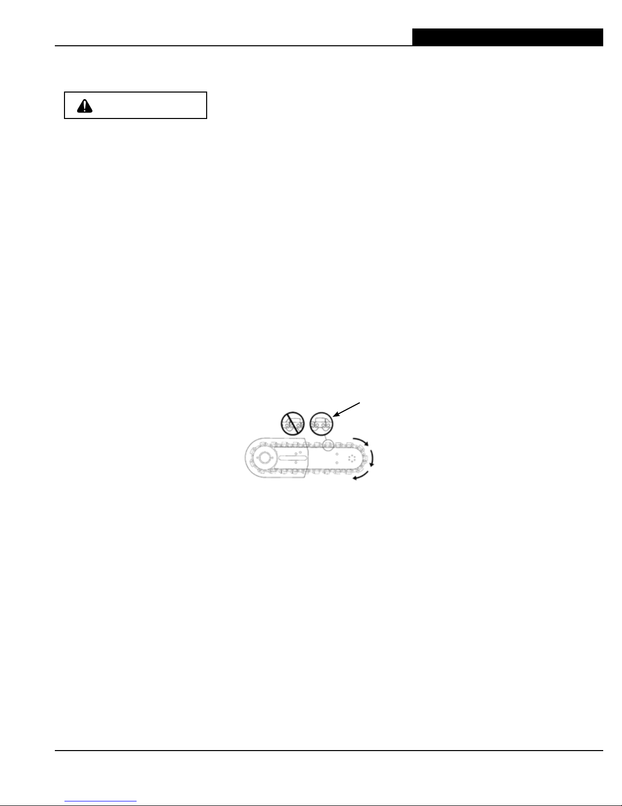
• Proper Diamond Chain Tension: The diamond chain should be tight but easily pulled around the
guide bar by hand.
• Ensure all safety devices are properly mounted and functional and that all controls are in proper
working order.
• Be sure there are no obstructions (plumbing, electrical conduit, air ducts).
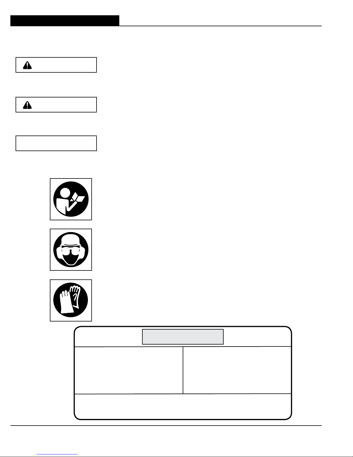
• Always wear protective clothing, including hard hat, eye protection, hearing protection, non-slip
safety boots, gloves, and avoid wearing loose fitting clothing.
• Adequate Water Supply and Pressure:
Minumum flow: 2 gpm (8 l/min)
Minimum water pressure: 20 psi (1.4 bar)
Note: The single most important factor an operator can control to increase chain life is to
use adequate water pressure. Insuffecient water supply will result in excessive wear to
the chain, which can lead to loss of strength and chain breakage.
• Proper Hydraulic Supply to the saw:
Maximum Flow: 12 gpm (45 l/min) fixed flow
Maximum Hydraulic Pressure: 2,500 psi (172 bar)
PLANNING THE CUT
• Outline the cut with a permanent marker for a visual cutting guide.
• Avoid pinching the guide bar and diamond chain. Always cut the bottom of an opening first, then
top, and then the sides. Save the easiest cut for last.
• For the straightest cuts use the “Step Cut” method. First score the entire cut line approximately a
half-inch deep using the nose of the guide bar. Next, deepen the cut by about two inches. Then
plunge all the way through and complete the cut using the Wallwalker®.
• Be sure cut concrete cannot fall and injure operator or bystanders. Concrete is very heavy, one
cubic foot = 12”x12”x12” = 150 lbs. (30cm x 30cm x 30cm = 68kg).
• Check for live electrical wiring near the cutting area or in the concrete to avoid electrocution.

TITLE
880 OPERATOR’S MANUAL
11
F/N 525665 Oct 07 © 2007 ICS, Blount Inc.
OPERATION
CUTTING TIPS
• To start a cut, hold trigger on full throttle and slowly plunge the nose of the guide bar straight into
the wall. Use the fixed Wallwalker®as a pivot point and pull up on the rear handle to rotate the
guide bar into the cut.
• Always operate the saw at full throttle. Apply enough feed force so that the free running RPM
drops 20 to 30%. If too much force is applied, the saw will lug or stall. The diamond chain will not
have enough speed to cut effectively. If too little feed force is applied, the diamonds will skid and
glaze over.
• For straighter cuts use the “step cut” method. First score the entire cut line with the nose of the
guide bar approximately 1/2 inch (12 mm) to 1 inch (25 mm) deep. Next, deepen the cut by about
2 inches (50 mm). This groove will help guide the guide bar for a straight cut. Then plunge all the
way through and complete the cut using the Wallwalker®.
• Use the Wallwalker®to help cut more efficiently and reduce operator fatigue. The Wallwalker®
is a fulcrum that converts inward force to downward force and will develop a 4-to-1 mechanical
advantage. To use correctly, plunge into the wall and simply engage the point of the Wallwalker®
into the cut and push straight in. The Wallwalker®will force the saw to feeed down.
• Apply upward force on th trigger handle to keep the Wallwalker®engaged properly, otherwise the
Wallwalker®pick will skid, which will reduce the effectiveness. As the saw begins to rotate up,
feed force is developed down the line of the intended cut. Once the saw is fully rotated upwards,
pull the saw out of the cut a few inches and re-engage the Wallwalker®to the wall and repeat.
• When cutting rebar, slowly ”rock” the saw so that you’re always cutting concrete as well as steel.
This will help keep the diamonds exposed. Also, expect less diamond chain life when cutting
rebar.
• Expect more diamond chain stretch and guide bar wear when making “nose buried” cuts for
extended periods of time, as the diamond chain does not have a chance to “throw” the slurry
away from the nose of the guide bar.
• If the saw begins to cut consistently crooked, turn the guide bar over and use the other side.
Dress worn rails with belt sander. Note: The normal life of a guide bar is 2 to 3 diamond chains.
Rebar can shorten guide bar life.
• When using a new diamond chain, you can increase the cutting speed by “opening up the
diamonds”. Make a few cuts in an abrasive material such as a cinder block.

TITLE 880 OPERATOR’S MANUAL
12 © 2007 ICS, Blount Inc. F/N 525665 Oct 07
OPERATION
SYSTEM CLEAN-UP
• After cutting, run the saw for at least 15 seconds with the water on to flush slurry and debris from
diamond chain, guide bar and drive sprocket.
• Wash concrete slurry from saw assembly.
• Avoid getting any water in the carburetor or exhaust system. If water enters exhaust port, point
the guide bar tip down and pull the starter handle several times to expel water from muffler.
• Remove guide bar and diamond chain. Flush out the chain tensioner with high water pressure
and lube with grease.
• After cleaning the saw, spray the entire saw body, diamond chain, guide bar, and drive sprocket
with lightweight oil. Using lightweight oil on the saw will minimize rust and help reduce slurry
build up.
MAINTENANCE

TITLE
880 OPERATOR’S MANUAL
13
F/N 525665 Oct 07 © 2007 ICS, Blount Inc.
MAINTENANCE
DRIVE SPROCKET REMOVAL
• STEP 1 – Prevent the sprocket from rotating by inserting the
scrench or screwdriver through the holes in the sprocket and
the hole in the saw body.
• STEP 2 - Loosen the Trantorque using a 7/8" box end
wrench.
• NOTE - Slurry will accumulate inside the trantorque adaptor
while cutting. This can fill expansion spaces and make it
difficult to remove. To faciliate removal, turn the hex nut
counterclockwise approximately 1/8 turn, and then turn it
clockwise slightly, so the hexnut is loose. Then lightly tap
the end of the ring inside the hex nut several times with
your box wrench. (This will loosen the slurry and allow the
components to slide for removal.) Continue to turn the hex
nut counterclockwise to free the sprocket and trantorque.
DRIVE SPROCKET INSTALLATION
• STEP 1 - Clean the drive shaft and Trantorque surfaces well
before installation (Isopropyl alcohol is reccommended, to
remove grease or hydraulic fluid).
Note: Do not lubricate Trantorque or shaft as slippage may
occur.
• STEP 2 - Slide the Trantorque shaft adaptor onto drive
shaft until it bottoms on the shaft. Note: Do not lubricate
trantorque or shaft as slippage may occur.
• STEP 3 - Slide drive sprocket onto the trantorque until it hits
the bottom of the shaft.
• STEP 4 - While holding the sprocket and trantorque as
close to the frame of hte saw as possible, finger tighten
trantorque shaft adaptor.
• STEP 5 - Stop the sprocket from roatating by inserting a
scrench or screwdriver through the holes in the sprocket and
the hole in the saw body.
• STEP 6 - Tighten the Trantorque shaft adapter with a torque
wrench and a 7/8" socket to 200 in-lbs (22.6 Nm). When a
torque wrench is not available, use a 7/8" box end wrench
and tighten one-half turn past finger tight.
Note: Do not turn around or reverse the direction of the
drive sprocket to extend sprocket tooth life. Damage to
chain or drive links may occur.

TITLE 880 OPERATOR’S MANUAL
14 © 2007 ICS, Blount Inc. F/N 525665 Oct 07
TROUBLESHOOTING
TROUBLESHOOTING
• SLOW DIAMOND CHAIN SPEED – Be sure the powerpack is providing the correct hydraulic
pressure and flow 12 gpm (45 l/min) fixed flow and 2,500 psi (172 bar)
• POOR CUTTING SPEED - Diamonds may be “glazed over”. Make a few cuts in an abrasive
material such as a cinder block to expose the diamonds.
• PREMATURE CHAIN STRETCH - Not enough water pressure. The minimum water pressure
rewquired is 20 psi (1.4 bar). Insufficient water supply will result in excessive wear on the chain,
which can lead to loss of strength and chain breakage.
• CHAIN TENSIONER BREAKAGE - Side cover nuts are not tight enough.
Torque to 20 ft-lbs (27Nm).
• WATER NOT FLOWING - Water hose is kinked or supply is not turned on.
• MOTOR WON'T TURN – Hydraulics are hookep up backwards or powerpack is set on reverse
flow.
Further questions?
Call 1-800-321-1240
or
visit our website at:
icsbestway.com

TITLE
880 OPERATOR’S MANUAL
15
F/N 525665 Oct 07 © 2007 ICS, Blount Inc.
REFERENCE
APPROXIMATE CUTTING RATES
Material Cutting Rate
Concrete - 6" (15 cm) 5 lineal in/min (12 cm/min)
Red Brick - 6" (15 cm) 10 lineal in/min (25 cm/min)
Rebar - #4 (12 mm) 10-20 seconds through each piece
INCH-FOOT DEFINITION
An in-ft is a measure of how much material is to be cut.
An in-ft is defined as: depth in inches times length in feet.
Note: 129 in-ft = 1m2
Example: How many in-ft are in this doorway?
1. Determine the depth of the cut in inches.
For this example, 8 inches.
2. Determine the length of the cut in feet.
3+7+3+7=20 feet
3. Multiply the two numbers
8 in x 20 ft = 160 in-ft

TITLE 880 OPERATOR’S MANUAL
16 © 2007 ICS, Blount Inc. F/N 525665 Oct 07
REFERENCE
PERFORMANCE LOSS VS. HYDRAULIC HOSE LENGTH
ASSUMPTIONS:
• 12 gpm (45 l/min) flow and 2,500 psi (172 bar)
• Zero elevation change
• 2 pairs of flush-face fittings per hose .


4909 SE International Way
Portland, OR 97222
Tel 800-321-1240 Fax 503-653-4393
icsbestway.com
880 OPERATOR’S MANUAL
© 2007 ICS, Blount Inc. F/N 525665 Oct 07
Table of contents
Other ICS Chainsaw manuals