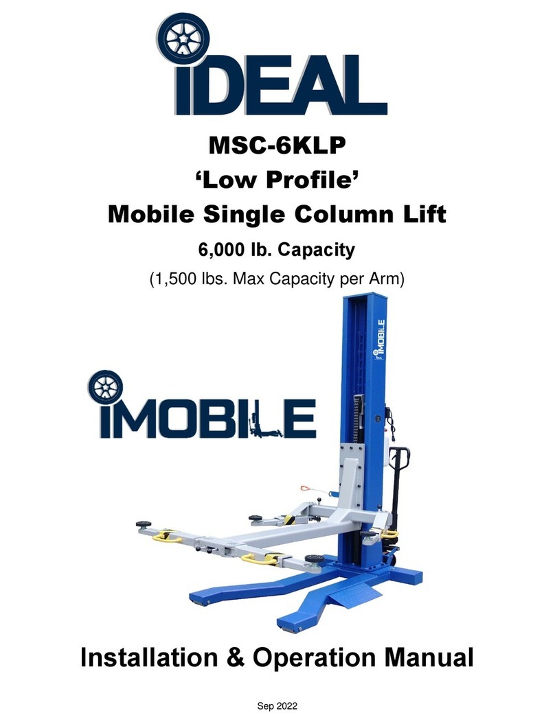
IDEAL MSC-13K-B User manual

Nov. 2021
Mobile Column Lift Set
MSC-13K-B
Capacity 13,200lbs / Each Column
Installation - Operation – Service Manual

2
Nov. 2021
MSC-13K
INDEX
CHAPTER 0. PREFACE----------------------------------------------------------------------------PAGE 2
CHAPTER 1. GENERAL----------------------------------------------------------------------------PAGE 3
CHAPTER 2. SET-UP / INSTALLATION -------------------------------------------------------PAGE 7
CHAPTER 3. CHARGING BATTERIES---------------------------------------------------------PAGE 9
CHAPTER 4. OPERATION INFORMATION --------------------------------------------------PAGE 10
CHAPTER 5. LIFTING OPERATION INSTRUCTIONS-------------------------------------PAGE 20
CHAPTER 6. STORE THE MOBILE COLUMN LIFT ---------------------------------------PAGE 24
CHAPTER 7. MAINTENANCE -------------------------------------------------------------------PAGE 25
CHAPTER 8. TROUBLE SHOOTING ------------------------------------------------------PAGE 26
CHAPTER 9. ELECTRO-OPTICAL ENCODER ALIGNMENT----------------------------PAGE 28
CHAPTER 10.SOFTWARE MENU LIST -------------------------------------------------------PAGE 29
CHAPTER 11.HAND-CONTROLLER (Optional)----------------------------------------------PAGE 30
CHAPTER 12.BATTERY CHARGER INFORMATON ---------------------------------------PAGE 32
CHAPTER 13.BATTERY REQUIREMENT INFORMATION--------------------------------PAGE 33
CHAPTER 14.EXPLODED VIEWS & PARTS LISTS-----------------------------------------PAGE 34
CHAPTER 15.LIMITED WARRANTY-------------------------------------------------------------PAGE 46
PREFACE
Prior to the operation of your lift make sure that you have read the
instructions thoroughly. These instructions are found in this
manual. Please note that your warranty can be voided if you do
not read the manual and understand its content.
If you have any questions, concerning operation, safety or
application of your lift, please contact your distributor.

3
Nov. 2021
MSC-13K
1. GENERAL
1.1 SPECIFICATIONS
OEM Item # / Model # 167215B / MSC-13K-B
Capacity 13,200 lbs. / Each Column
Pressure Relief Valve 2,030 psi Sealed Ex-Works
Pump motor 3HP ( DC24V, Max 110Amper ) / Each Column
Battery charger power
supply Input: 100-140 , 60Hz, single phase
Output: 24VDC, Max 15Amper
Operational Voltage 24 VDC
Lifting Height 67.1"
Column L / W / H 45.7” / 44.1” / 88.6” (Max Ht. 155.5”)
Fork Adjustable Range 6.3” - 22”
Fork length 14”
Lifting / Lowering Time 75 sec/ 60 sec at load of 13,200 lbs. / each column
Noise Level Max. 70 dB(A)
Set-up Indoors
Unit Weight 1,200 lbs. per Column
Maximum Distance
between Columns 32.8'
Min. Concrete Surface
Strength 3000 Psi

4
Nov. 2021
MSC-13K
1.2 DIMENSIONS ( mm / inch)
Fig.1 Mobile Column Lift Dimensions

5
Nov. 2021
MSC-13K
1.3 DESCRIPTION OF THE LIFTING SYSTEM
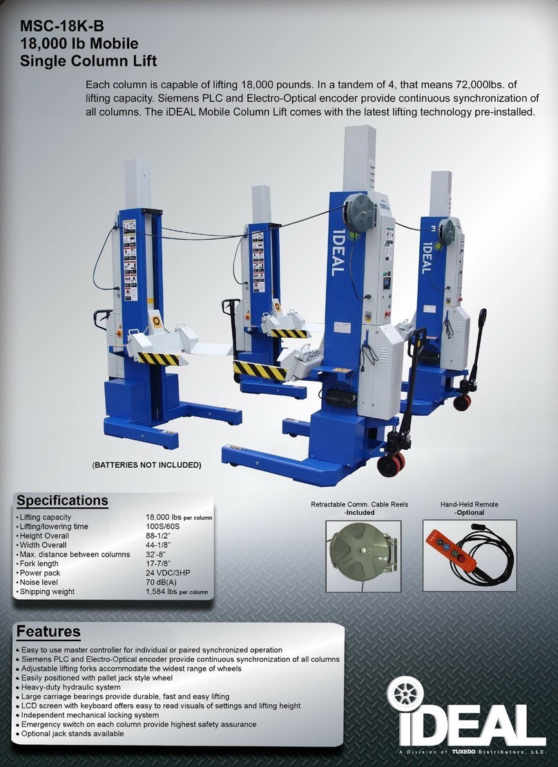
The mobile column lift is a movable electrically driven hydraulic column lift used for
lifting heavy vehicles. It is used in set of four columns. But at least two lifting columns
are required to work at same time for lifting a vehicle.
The main components of the mobile column lift are shown below: (see figure 2):
1) Height sensor / encoder
2) Safety lock mechanism
3) Control case
4) Motor pump
5) Pallet jack
6) Battery (Not Included)
7) Front roller
8) Battery case
9) Forklift pocket
10) Lifting fork
11) Carriage
12) Hydraulic cylinder
Fig.2 column components
Each lifting column has a lifting capacity of 13,200 lbs. Consequently, four columns
have a total lifting capacity of 52,800 lbs.
Each column has its batteries to drive the motor pump (hydraulic power unit).
The control system on the lifting columns ensures that the columns are raised or
lowered synchronically. Each lifting column is equipped with a position sensor, which
transmits the height readings to the control system. The control system controls and
protects the lifting system during lifting or lowering as follows:
- At a difference in distance passed in height between the lifting columns of over 3/4"
(20mm) and less than 2" (50mm), an extra adjustment valve in the hydraulic system
opens and remains open until the difference has been cancelled out. The adjustment
happens in the lift, which has passed the largest distance.
- At a difference in distance passed in height of over 2" (50mm), lifting or lowering is
interrupted in the quickest lifting column. It will stop to until the difference has been
cancelled out.
In addition, the control system has been designed so that:
- Each lifting column can be operated separately
- Any pair of axles can be handled individually

6
Nov. 2021
MSC-13K
1.4 STRUCTURE OF THE MOBILE COLUMN LIFT
• Hydraulic Power Unit
The hydraulic system consists of an electrically driven pump, flow control valves,
control valves and an oil reservoir.
• Column and Lifting Cylinder
The column and lifting cylinder form the major part of the portable column lift. In
the U-section of the column there are a guide block and rollers. The rollers enable
the guide block to move along the full length of the column. The hydraulic lifting
cylinder provides the lifting capacity.
• Control Box
The control box has all the functions controlling the use of the lifting column. The
control box components and functions have been specified in GENERAL USE
sections.
• Pallet Jack Mechanism
The two-wheel pallet jack mechanism serves to move the lifting column. The two
wheels protect the lifting column from being turned over at the back when it is moved.
The pallet jack mechanism lifts the column off the floor so that the column can be
easily moved.
• Mechanical Safety Lock
If the hydraulic pressure fails while a vehicle is on the lifting system or is lifted or
lowered, a mechanical safety lock ensures that it cannot drop.
The characteristic clicking of the safety lock when rising indicates that it is activated.
During lowering the pawl is retracted by a solenoid magnet.
• Adjustable Forks
The adjustable forks are designed for different vehicles with different wheels. The forks
can be adjusted manually to accommodate a wide range of tire sizes. The mechanical
lock-pins prevent the forks from moving sideways under load.

7
Nov. 2021
MSC-13K
2. SET-UP / INSTALLATION
Remark: Only move the lifting column with the forklift. Only raise the lifting column at
the correct points. Damage to lifting column and /or injury to persons may
occur if the lifting column is not moved in the correct manner.
2.1 UNPACKING AND HANDLING THE LIFTING COLUMN
STEP 1. Handling of Lifting Columns
1. Remove the cover from the crate or, when using a stand, remove the straps.
2. Carefully insert forklift forks into the forklift pockets. The pockets are bolted to the
column before leaving factory. (Figure 3).
Fig. 3 Forklift Pocket on Column
Fig. 3-1
3. Lift the column then move it to the working position.
STEP 2. Fill the Tank
1. Take off the forklift pockets from the mobile column lift (better).
2. Remove the cover from the hydraulic unit. Remove the plug from the fill opening
and fill the tank with hydraulic oil: AW32, 46 or other good grade Non-detergent
hydraulic oil SAE-10, filleted at 4 micron max, about 15L (3.3 Gal) .(Fig. 3-1)
3. Install the breather cap on the fill opening.
4. Install the cover back on the hydraulic unit.
5. Check for oil leakage.

8
Nov. 2021
MSC-13K
STEP 3. Battery Installation
1. Remove Battery Covers (Fig. 4)
2. Seat and fasten the batteries on the column base, secure to base using provided
metal straps.
3. Connect the power cables to batteries. ( Fig. 4)
Fig. 4 Battery Installation
NOTE: Ensure to correctly connect terminals: Red/Pos. = (+), Black/Neg. = (-)
4. Install the battery covers back on lift.
STEP 4. Cable Reel Installation
1. Take out the cable reels from the carton.
2. Insert the holding frame into the base on the upper cover (Figs. 4-1a & b)
Fig4-1a Fig.4-1b Fig.4-1c
3. Pull up and pull down the upper and down lock button, the reel can turn aside.
(Fig. 4-1c)

9
Nov. 2021
MSC-13K
4. Fix the reel on the base by the screw. (Fig 4-1d)
Fig.4-1d Fig.4-1e
5. Put the cable plug into the socket. (Fig 4-1e)
6. Repeat the above steps for the other three columns
3. CHARGING BATTERIES
After one day’s operation or the battery indicator [22] shows the voltage is low, it is
suggested to charge the batteries. Different batteries need different charging time.
Please refer to the manual of the battery.
a) Move the columns near the AC power supply ports on the wall.
b) Connect the charger to the AC power supply. (Fig. 10)
c) Turn the power switch to the right position (CHARGE) on each column.
d) While charging, the red CHARGING indicator will be lighted. After the batteries
are fully charged (about 10 hours), the green FINISH indicator will be on and red
indicator will go off.
Battery Charger Socket Switch ChargerIndicator
Fig. 10

10
Nov. 2021
MSC-13K
4. OPERATION INFORMATION
4.1 CONTROL PANEL FEATURES
The Main Control Panel controls the main power. All other functions of the lifting system are
controlled from the Control Panels on the columns. The functions of the switches, buttons on the
control system are described below.
Main Control Panel - #1 Column
Sub
Control
Panels
-
#2, #3 & #4 Columns
24

11
Nov. 2021
MSC-13K
4.2 CONTROL PANEL DETAILS
1. EMERGENCY BUTTON
Button to stop movements (lifting or lowering) immediately.
2. POWER SWITCH
Controls the power of the control panel or charging of the batteries.
3. “⇑(UP)” button
Controls the lifting of the columns.
4. “⇓(DOWN)” button
Controls the lowering of the columns.
5. “⇓(PARK)” button
Controls the locking of the columns.
6. “POWER” light.
This light will go on when the control panel is power on.
7. 8. 9. 10. CURSOR buttons.
These buttons move cursor on the screen to edit items.
11. 12. 13. MODE buttons.
These buttons serve to select between the functions: “WHEEL”, “AXLE” &
“ALL”
14. “BIAS” button
To set the zero point of height readings in initialization.
15. “START” button
This button starts the running of the software.
16. “SHIFT” button.
This button is for the running of the program.
17. “ENTER” button
This button serves confirming of instruction or entering sub menu.
18. “ESC” button
Serves to enter or exit from menu; or from sub menu to upper lever menu.
19. LCD SCREEN
Display the height readings of columns & information
20. “WARNING” light
This light will go on when the EMERGENCY button is pressed.
21. CABLE PORT
This port is used for communication cable connection.
22. BATTERY INDICATOR
This indicator shows the output voltage of the batteries.
23. HAND / REMOTE CONTROLLER PORT
The port is for hand/remote controller connection
24. BATTERY SWITCH
To connect or disconnect the DC power supply.
Also use as column emergency switch.

12
Nov. 2021
MSC-13K
4.3 POSITIONING LIFTING COLUMNS
A fully combination consists at least of 4 lifting columns. The position of the main
column 1# should be located opposite with column 2# loading the same axel of the
vehicle. The 4# shall be at the other end of the same axel with 3#. (Fig. 6)
A set has a maximum lifting capacity of 52,800 lbs. This is the maximum lifting capacity
of a standard set of 4 lifting columns of 13,200 lbs. each.
Fig. 6 Positioning Columns

13
Nov. 2021
MSC-13K
4.4 DESCRIPTION OF THE MOBILE COLUMN LIFT SYSTEM
The mobile column lifts are designed in such a way as to offer maximum flexibility and
convenience. A lifting system can consist of 4 lifting columns. The control system is
equipped with the following features:
- Simultaneous operation of all lifting columns
- Operation of one lifting column.
- Operation of pair/axle lifting columns.
Each lifting column is provided with these control functions. But the RUNNING MODE
shall be settled by the MODE buttons on the main column control box first.
The mode of the mobile column lift is set-up as following:
1. Position the lifting columns as indicated in 4.3 (Fig. 6.)
2. Then turn on the battery power switch of each column on the side. (Fig.7a)
Fig.7a Fig.7b
3. Set the control box power switch [2] (Fig. 7b) on each sub column to left position
(ON) first, the green Power indicators [6] will be on.
4. Then turn on the switch [2] (Fig. 7b) on main column to left (ON) and the LCD screen
[19] is lighted. Wait until the LCD screen changed to the 4th display, press the
START [15] button to start running of the system.
LCD screen 1st LCD screen 2nd
LCD screen 3rd LCD screen 4th
TD 400C
Version 2.0.0.X
INITIALIZING…
Please wait…
TB6 Controller VX.XX
Copyright @ Kernel
Curr. status: RESET
Self-Checking…
TB6 Controller VX.XX
Copyright @ Kernel
170cm 4 Lifts Z___
Push START to confirm

14
Nov. 2021
MSC-13K
Note: If necessary, the lifting height / travel distance shall be changed before
press SHIFT and START buttons. (See 3.4 section)
5. Take care that the emergency stop button of each lifting column must been
released.
6. Operation description
All system functions are available by press the MODE buttons [11], [12], [13] when
the lift columns are not in operation (non of button [3], [4], [5] is pressed).
When the Mode is ALL / Vehicle ( II..II )
-Press any button 3 ⇑, all columns are raised.
-Press any button 4 ⇓, all columns are lowered.
-Press any button 5 ⇓, all columns are lowered and locked.
When the Mode is WHEEL / Single ( I )
-Press one button 3 ⇑, that column is raised.
-Press one button 4 ⇓, that column is lowered.
-Press one button 5 ⇓, that column is lowered and locked.
When the Mode is Axle / Pair ( II )
-Press one button 3 ⇑, that two columns in same axle are raised.
-Press one button 4 ⇓, that two columns in same axle are lowered.
-Press one button 5 ⇓, that two columns in same axle are lowered and locked.
Note: In WHEEL or AXLE mode, the lifting or lowering will be stopped when the
height difference between columns or axles is greater than 2” (50 mm)

15
Nov. 2021
MSC-13K
4.5 TRAVEL DISTANCE AND HEIGHT UNIT CHANGING
4.5.1 TRAVEL DISTANCE CHANGE
If the lifting height is less than 67” (170cm) due to low shop ceiling, the travel distance
shall be set in following steps before starting the lifting operation.
1. After power on, waiting the LCD screen to be the LCD screen 4th, then press ESC
button [18] to change to system menu. ( LCD screen 5th )
2. When ‘USER MENU’ is high-lighted, press ENTER button [17] to enter the sub
menu of USER MENU. ( LCD screen 6th )
LCD screen 5th LCD screen 6th
LCD screen 7th
3. Press DIRECTION DOWN button [8] to move to ‘Set of Travel’ as in LCD screen
6th.
4. Press ENTER button [17] again to enter the travel distance modification screen.
(LCD screen 7th)
5. To change the travel distance, using ‘DIRECTION‘ buttons [7], [8], [9] and [10] to
move cursor to the percentage on the screen then change the number.
Note: The percentage range is 60%--100%. Min. step is 2” (5cm).
6. Press ENTER to confirm the modification and press ESC to exit this function to
upper menu. (LCD screen 8th)
4.5.2 HEIGHT UNIT CHANGE
1. From LCD screen 6th, Use ‘DIRECTION’ buttons to choose ‘Set of Unit’.
(LCD screen 8th)
2. Press ENTER button [17] to enter the unit modification screen. (LCD screen 9th)
3. To change the unit, using ‘DIRECTION’ UP and DOWN buttons [7], [8] to
change the number. ‘1’ refers to inch. ‘0’ refers to cm.
USER MENU
OPERATOR MENU
DIAGNOSTICS MENU
RELEASE PASSWORD
Parameters List
Set of Travel
Set of Unit
Special Terms
1. Use arrow key to edit:
Max. % Travel
170 X 100 >= 170 cm
2. Press ENTER then ESC

16
Nov. 2021
MSC-13K
4. Press ENTER [17] to confirm the modification and press ESC [18] to exit
this function to upper menu. (LCD screen 8th)
LCD screen 8th LCD screen 9th
4.5.3 UNIFORM HEIGHT REFERENCE
After travel distance and unit modification, the screen is back to LCD screen 4th. If
press START button (15) at this step, the screen change to 10th.
or
LCD screen 10th
(Here the L1, L2, L3, L4, L5, L6 are to indicate the position of height reading of each
column. They are not shown in screen in operation)
In this LCD screen 10th, the bias ‘Z___’ means the system height reference is in
uniform height reference. The height reading is zero while the lifting fork at the bottom
as it is set in factory. While in VEHICLE mode or AXLE mode, the lifts will be in same
height while lifting or lowering
The right row L5 and L6 reading (0, 0) in the screen is no meaning. The software can
work for 6 columns in all for cable model.
4.5.4 CUSTOMIZED HEIGHT REFERENCE
If for any reason, the height of different column shall be kept differently, (difference is
greater than 2”/50 mm), the Customized height reference shall be chosen as following.
1. Press WHEEL / SINGLE button [11] change the screen into LCD screen 11th.
2. Press UP button [3] on one column to raise single column to desired height. Repeat
for other three columns.
WARNING!!
In this step, the height of each column shall keep the vehicle in horizontal.
Never try to rise up too much or it will cause vehicle to move, to drop. Each
pressing can only keep moving for about 5 seconds.
Parameters List
Set of Travel
SetofUnit
Special Terms
Unit: Current 0 cm
1. Use arrow key to edit:
0---cm; 1---inch
2. Press ENTER then ESC
Mode: II..II bias: Z___
L2 0L40L60
L1 0L3 0L50
⊙
Stop
!
Mode: II..II bias: Z___
L2 0L40L6 0
L1 0L3 0L5 0
Reset

17
Nov. 2021
MSC-13K
3. Press BIAS button [14] for 2 to 4 seconds. The system changes into customized
height reference system: ‘C-_-‘. The LIFTING MODE will change into ALL /
VEHICLE automatically. (LCD screen 12th)
LCD screen 11th LCD screen 12th
The height of every column (4, 1, 3, 2 in the LCD12th) is memorized as the
customized zero points.
Note:
1) The customized zero-point height reference can only be performed just after
LCD screen 9th display. Any lifting operation (UP, DOWN, PACK) in MODE
ALL or AXLE will cancel the performance and keep the reference system to
be UNIFORM immediately.
2) Under customized zero-point height reference, if all columns’ height are below
theirs customized zero points and at least one column within 6” (150mm) to
the ground, the reference will be back to uniform reference, SINGLE and the
‘Z___’ will be on the screen again.
3) So, to change the height reference system (also travel distance or height unit)
second time, operator shall wait all lifting forks in lowest (ground) position and
the LCD screen is 10th again.
Mode: I bias: Z___
0 0 0
0 0 0
Mode: II..II bias: C-_-
1 2 0
4 3 0

18
Nov. 2021
MSC-13K
4.6 ADJUSTING LIFTING FORKS
The portable lifting columns can be used to lift vehicles with a wheel diameter of R7
(9”/228mm) to R22.5 (45”/1140mm). The forks can easily slide to the correct
dimension:
1 Lift lock-pin to unlock the fork.
2 Use both hands to slide the fork sideways. Adjust both forks so that they are
equally spaced in relation to the centre of the column.
3 Adjust so that the forks at floor height just fit around the tire (to prevent the
rim falling through, when tire becomes deflated) (Fig.8)
4 Make sure that the lock-pin locks-in to place.
Fig.8 Adjust Forks to fit the Wheel

19
Nov. 2021
MSC-13K
4.7 OPERATING THE PALLET LIFTING MECHANISM
The pallet jack mechanism is operated by means of the handle bar and the lever
inside the bar. (Fig. 9)
The lever has two positions:
1 When the lever is pulled up in the upper position (1), the pallet jack mechanism
can be raised by moving the handle bar up and down.
2 If hand released, the lever will be back to its neutral position. The pallet jack
mechanism is lowered and the lift will sit on ground.
Fig. 9 Pallet Lifting
Steps to move the column lift with pallet jack:
1 Pull up the lever to position (1) and make some pumping movement with the
handle bar to raise up the column lift. Then the column lift can then be relocated.
2 Release the lever to position (2) to lower down the column lift to the floor
after it is right located.
Note: Set the pallet lifting mechanism in the lowest position, and the lever to
the neutral position (2), whenever the column lift is to hoist a vehicle.

20
Nov. 2021
MSC-13K
5. LIFTING OPERATION INSTRUCTIONS
The assembled lifting system must be checked for correct working and
adjustments and a complete operational test should be carried out by using a
typical vehicle.
Remarks:
-When using this lifting system, leave a space for a 24” (600mm) wide passage
around the lifting system, which can serve as escape route.
-Before using the Portable Lifting Columns, ensure that the maximum load for
each lifting column is not more than 13,200 lbs.
-Ensure that before use, the lifting system is placed vertically seen from the
sides as well as from the front.
-Make sure that the pallet jack mechanism is fully lowered before lifting a vehicle.
5.1 PREPARATION & IMPORTANT NOTICE
1. Place all the four of lifting columns around the vehicle as in Fig.5.
2. Ensure that the fork of each lifting column is slid around the wheel as far
as possible. ( The forks shall have been adjusted as in Fig.6 )
3. Move the columns’ forks under the wheel.
4. Lower the pallet jack mechanism by releasing the lever inside the handle
bar.
5. Make sure all of the power switches on the control boxes are set to 0
(OFF).
6. Make sure that the Emergency Release buttons are unlocked on all the
lifting columns.
7. Set all the power switches to left position (ON). (Main column to be the
last one)
8. Press button START on the main control box to run the software.
9. Set the mode to be WHEEL / SINGLE by pressing button [11].
This manual suits for next models
1
Table of contents
Other IDEAL Lifting System manuals

IDEAL
IDEAL TLX-7000-FLRAILKIT User manual

IDEAL
IDEAL LT-PT2500AH-X Supplement

IDEAL
IDEAL FP14KC-X User manual

IDEAL
IDEAL TP10KAC-DX User manual
IDEAL
IDEAL U-2200IEH-XR Instruction manual

IDEAL
IDEAL UTV KIT User manual

IDEAL
IDEAL A-2200IEH-XR Instruction manual

IDEAL
IDEAL TP12KSC-DX User manual

IDEAL
IDEAL MSC-6KLP User manual

IDEAL
IDEAL 7000TLX Supplement
Popular Lifting System manuals by other brands

Aqua Creek Products
Aqua Creek Products Patriot-AT1 instruction manual

Peak
Peak AMGO 414 Installation and service manual

Nexus 21
Nexus 21 L-75ix installation manual

STARKE ARVID
STARKE ARVID 23000 Instructions for use

Boat Lift
Boat Lift Up-N-Over installation instructions

IKAR
IKAR ASS-4 Log book and instructions for use