IDEAL LT-PT2500AH-X Supplement

LT-PT2500AH-X
FEB 2024
LT-PT2500AH-X
POWERTRAIN LIFT TABLE
(AIR / HYDRAULIC OPERATION)
2,500 lbs. Capacity (1134 Kg)
ASSEMBLY & OPERATION
MANUAL
IMPORTANT!!
READ MANUAL THOROUGHLY BEFORE ASSEMBLING, OPERATING, OR MAINTAINING LIFT
TABLE. WHEN COMPLETED WITH ASSEMBLY, ENSURE TO RETURN MANUAL & RELATED
DOCUMENTS IN PROTECTIVE SLEEVE AND GIVE TO THE OWNER / OPERATOR.

2
LT-PT2500AH-X
FEB 2024
Table of Contents
1. Safety & Cautions……………………………………………………………………Pages 3 - 4
·Important Statements
·Qualification of Operators and Users
·Cautions
·Training
·Owners / Employer Responsibilities
2. Product Information & Requirements…………………………………………Pages 4 - 6
·Description
·Specifications
·Dimensions
·Receiving & Handling
·Required Tools
·Selecting Site
3. Assembly Instructions…………………………………………………………….. Pages 7 - 8
·Removal of Lift Table From Wooden Crate
·Mounting Handle Bar to Lift Table Base
·Mounting Air System Control Box to Handle Bar
·Replace Oil Reservoir Plug with Vent Plug
·Compressed Air Supply Fitting Connection
4. Starting Up / Testing……………………………………………………………….. Page 9
·Air System Controls (Diagram)
5. Operation Instructions……………………………………………………………..Pages 10 - 11
·Positioning, Lifting & Lowering Heavy Loads
·PT Lift Table Feature Tips
6. Troubleshooting………………………………………………………………………Page 12
·Power Unit Priming Procedure
7. Inspection, Maintenance & Cleaning………………………………………… Page 13
·Before Each Use (Pre-Operation Check)
·Weekly Maintenance
·Yearly Maintenance
·Cleaning
Exploded Views……………………………………………………………………….Pages 14 - 17
Parts List……………………………………………………………………………….. Pages 18 - 20
Limited Warranty Policy……………………………………………………………Page 21

3
LT-PT2500AH-X
FEB 2024
1. Safety & Cautions
Important Statements:
Please note the max weight capacity noted on the decal applied to side of the outer scissors and on
the silver ID tag attached to the inner scissor. Do not try to lift any load that exceeds the rated lifting
capacity. Please read this manual carefully before assembly and use of the lift table, to avoid any
property loss or personal injury caused by faulty operation. No one is allowed to modify the controls,
parts, or other mechanical parts of the machine without the manufacturer’s permission.
Qualification of Operators and Users:
·Only personnel who have received training are allowed to operate and use lift table.
·Non-professionals shall not approach the lifting area during use.
Cautions:
·Do not use lift table on asphalt or any type of soft surface. Concrete thickness & strength must
meet requirement to safely support lift table and the applied load.
·Please read and understand Safety Cautions carefully before operation of lift table.
·The lift table shall not be used outdoors if not customized to meet special water proofing
requirements.
·Hands and feet shall be kept away from moving parts of the lift at all times.
·Only personnel who have received training are allowed to operate and use the lift table.
·Operators should not wear loose clothes to avoid being clamped by any moving part when the
machine is descending or rising.
·Floors & surrounding area around lift table must be kept clean to help avoid accidents and
possible lift table malfunctions or maneuvering issues.
·When possible, lower lift table onto safety latches after raising platform to the desired height,
especially for heavy loads and/or for long time durations.
·Ensure the item(s) being raised & lowered are properly balanced & secured to platform.
·Check for any missing, broken or seized parts or components that may contribute to improper
wear & tear. Once any anomaly is detected, stop use immediately and contact the dealer.
·Always fully lower lift table prior to maneuvering to another location, loaded or unloaded.
·It is not allowed to modify any part of the lift without the manufacturer’s permission.
·Anyone who will be in the vicinity of the lift table when it is in use should familiarize themselves
with any CAUTION, WARNING, and SAFETY related decals supplied with this lift table.
Replace if decals become illegible or missing.
·If the lift table is to stand idle for a long period of time, it is recommended the user shall:
a. Lower to minimum height & engage casters locks.
b. Remove air supply hose from air fitting.
c. Check & drain any water from bottom of the water separator reservoir.
c. Lubricate moving parts.

4
LT-PT2500AH-X
FEB 2024
Training:
Lift table operators must be qualified & trained for safe use and proper operation, as described in
Manual.
Owner / Employer Responsibilities:
This is a lift table assembly / operation manual, and no attempt is made or implied herein to instruct
the user in lifting methods particular to an individual application. Rather, the contents of this manual are
intended as a basis for operation and maintenance of the unit as it stands alone or as it is intended and
anticipated to be used in conjunction with other equipment.
Proper application of the equipment described herein is limited to the parameters detailed in the
specifications and the usages set forth in the descriptive passages. Any other proposed application of
this equipment should be documented and submitted in writing to the factory for examination. The user
assumes full responsibility for any equipment damage, personal injury, or alteration of the equipment
described in this manual or any subsequent damages.
2. Product Information
Lift Table Description: (LT-PT2500AH-X)
The iDEAL LT-PT2500AH-X is a 2,500 lb. portable, high-rise industrial grade air-hydraulic lift table,
incorporating a multi-adjustable powertrain platform primarily designed to assist with controlled lifting &
lowering tasks to safely remove, replace or service heavy vehicle powertrain components such as
engines, transmissions, drive-axle & transaxle assemblies, or other similar heavy components. The
LT-PT2500AH-X comes standardly equipped with a durable multi-adjustable powertrain platform that
includes expanded length, tilt & height adjustments, while also incorporating an exclusive fully
operational pneumatic hand operated ‘stainless-steel’control panel with integrated air gauge & water
separator. In addition, iDEAL Powertrain 2500 lb. Lift Table comes standard with high-quality locking
swivel & directional poly casters, tool tray, removable hand bar, double lift scissors, HD air-hydraulic
pump & hydraulic cylinder, tie-down anchors, and heavy duty ratchet strap. Optional ‘quick mount’PT
Support Stand Kit also available, providing additional support for various powertrain components.
Specifications:
Lift Model LT-PT2500AH-X
Capacity 2,500 lbs.
Overall Length 71.3"
Overall Width 33.5”
Max PT Platform Height 72"
Min PT Platform Height 35"
Hand Bar Height 39.2”
PT Platform Adj. Size (L x W) 31.5”to 36.7" x 23.6"
PT Platform Adj. Tilt Angle (+/-) 6º to 8º
PT Platform Locking Heights 49”, 61”, 68”
Lifting / Lowering Rate 72S / 33S
Power Supply (Compressed Air)
90 - 125 PSI (6 - 9 Bar)
Ship Weight 798 lbs.

5
LT-PT2500AH-X
FEB 2024
Dimensions: (LT-PT2500AH-X)

6
LT-PT2500AH-X
FEB 2024
Receiving & Handling:
Unloading Lift Table Crate: The Lift Table may be delivered with LTL lift gate service from the
freight carrier, which a pallet jack or dolly with a minimum of 1,000 lb. capacity will only be required to
remove crate from lift gate, in most cases. If not able to deliver with lift gate service, then a forklift or
shop type crane able to support a minimum of 1,000 pounds will be required to offload from the back
of freight carrier trailer. The lift table crate packaging weighs close to 1,000 pounds, not including any
optional accessories that may be included.
Required Tools:
ØPallet Jack or Fork Lift (Min. 1,000 lb. Capacity)
ØCrow Bar / Hammer
ØHD Scissors or Utility Knife
ØSocket Wrenches with Ratchet
ØAdjustable Wrench
ØPhilips Screwdriver
ØGloves
ØSafety Glasses
ØGloves
Selecting Site:
NOTE: Before assembling and operating your new lift table, ensure to check the following:
Overhead Obstructions:
The area where the lift table will be operated should be free of any overhead obstructions such as heaters,
building supports, electrical lines, etc.
Floor / Surface Requirements:
Do not use lift table on asphalt or any type of soft surface. Concrete thickness & strength must meet requirement
to safely support lift table and the load being applied. Also ensure lift table is used & operated on dry, grease
free, level concrete surface. Do not operate lift table on concrete expansion seams or cracked, defective
concrete.
WARNING!!: Failure to adhere to foundation requirements may cause lift table instability, which
could result in personal injury and/or property damages.
Operating Conditions:
The lift table is not intended for outdoor use and has an operating ambient temp range of 41º - 104ºF (5º - 40ºC).
CAUTION: DO NOT use lift table outdoors unless special consideration has been made to
protect from weather conditions.

7
LT-PT2500AH-X
FEB 2024
3. Assembly Instructions
WARNING!! Improper assembly can cause accelerated wear, resulting in catastrophic failure
which may cause property damage and / or bodily injury. Manufacturer will assume no liability
for loss or damage of any kind, expressed or implied, resulting from improper installation or
use of this product. Read this installation manual in its entirety before attempting to assemble
or operate the lift table.
Step 1: Removal of Lift Table From Wooden Crate
NOTE: It is recommended removing lift table from wooden crate using a forklift, with a minimum
of 1,000 lb. capacity. Lift table is elevated & secured to wooden blocks inside crate.
1) Using gloves, carefully remove banding straps secured around crate with heavy duty scissors or utility
knife.
2) Remove lid, using a crow bar or hammer, beginning at one corner. Set aside, once removed.
3) Open one of the crate’s ‘wide’side walls, by bending all metal tabs at each corner end. Once metal tabs
are aligned to tab holes, use hammer to help remove side wall from crate walls. Set aside, out of way,
once removed.
4) Carefully, use forklift to remove lift table from support blocks inside crate, ensuring to position forks width
to be inside of support blocks, clear of caster wheels. Raise lift table using the underside the lift table
frame, ensuring the forklift forks fully contact & support the whole frame.
5) Once lift table is slightly raised off support blocks, double check for any clearance issues, then carefully
back lift table out of crate with forklift, and lower to the ground for assembly steps.
Step 2: Mounting Handle Bar to Lift Table Base
1) Remove handle bar from the lower table base platform and remove packaging. Insert the handle bar
ends into the tubular sockets positioned at the trolley / power end of lift table’s base.
2) Secure with M10 x 20mm bolts, ensuring both bar ends are fully inserted into tubular sockets. Fig. 1.
Fig. 1
Handle Bar
Tubular
Sockets
M10 x 20mm
Bolts

8
LT-PT2500AH-X
FEB 2024
Step 3: Mounting Air System Control Box to Handle Bar
1) With thehandle barmounted&secured,find thepre-assembled‘stainless-steel’air system control
box located in the tool tray at the base of the lift table. Fig 2.
2) Carefully raise & position the air system control box to align its base plate holes to the upper holes
on the left handle bar side, ensuring not to loosen, detach or pinch the pre-routed airlines. Mount the
control box assembly to handle bar with 2ea M6 x 45mm screws & M6 lock nuts. Fig. 3.
3) Mount the ‘stainless-steel’airline protective cover on the vertical section of left handle bar, using
2ea M6 x 45mm screws & M6 lock nuts. Carefully ‘group’airlines together when aligning &
mounting protective cover, so not to pinch or damage airlines. Fig. 4.
Fig. 2 Fig. 3 Fig. 4.
Step 4: Replace Oil Reservoir Plug with Vent Plug
1) On the air-hydraulic pump, locate & remove the black ‘shipping’plug on the reservoir tank with
wrench and replace with brass ‘vented’plug, located in the plastic bag. Fig 5.
Step 5: Compressed Air Supply Fitting Connection
1) On the outside of the air system control box, connect the ‘quick disconnect’air ‘inlet’fitting to
the inlet port on the air regulator. Ensure air fitting connection is properly tightened. Fig 6.
2) Connect compressed air supply to the air inlet fitting with air pressure set at 90 to 125 PSI.
Fig. 5 Fig. 6
Air System Control Box
&
Airline Protective Cover
M6 x 45mm
Screws & M6
Lock Nuts
Air System
Control Box
Airline
Protective
Cover
NOTE:
Replace the
Black ‘shipping’
Plug with Brass
‘vented’ Plug
before Lift Table
Operation!
‘Quick Disconnect’
Air ‘inlet’ Fitting
Connection
Air-
Hydraulic
Pump
Brass ‘vent’ Plug
Plastic Bag
Black ‘shipping’ Plug
(Not Shown)

9
LT-PT2500AH-X
FEB 2024
4. Start-Up / Testing
CAUTION: Prior to the Start-Up / Testing, visually inspect lift table for any signs of damages,
defects and/or any missing or loose components. If any issues are discovered, DO NOT perform
the Start-Up / Testing procedure, and contact the dealer to resolve.
NOTE: Perform Start-Up Test without placing a load on lift table.
Air System Operation Controls
IMPORTANT: Ensure compressed air supply is set at 90 to 125 PSI for proper lift table
operation and performance. Check air fitting connections for proper tightness.
NOTE: The integrated lift table air regulator has already been pre-set at the factory for optimal
performance.
A. Position the Toggle Lever to the ‘UP’ position. (The air-hydraulic pump will prime the
hydraulic oil into the hydraulic cylinder and the lift table platform will begin to rise with safety
latches passing over the welded safety latch blocks at the base of lift table frame.)
B. Position the Toggle Lever to the ‘STOP’ position. (The air-hydraulic pump will cease
operation, stopping the lift table from rising.)
C. Position the Toggle Lever to the ‘DOWN’ position. (The lift table will fully lower to the lowest
height, as the hydraulic release valve is opened, and the safety latches are disengaged.)
D. Position the Toggle Lever to the ‘STOP’ position, then Press & Hold the Green ‘LOCK’
Button. (The lift table’s safety latches will engage, and the lift table will lower to the next lowest
safety latch position.)
E. Cycle Lift Table fully ‘Up & Down’ a couple of times. (This helps ensure all air is removed
from the hydraulic system, while also helping to familiarize with the operational controls.)
WARNING: Never Operate the Lift Table if the Safety Latch Mechanism is not working properly.
THE LIFT TABLE IS NOW READY FOR OPERATION.
Toggle Lever
‘GREEN’ LOCK
Button
(Side of Box)
‘Pre-Set’
Air Regulator
& Gauge
Water Trap Reservoir
& Drain Plug
(Inside Box)

10
LT-PT2500AH-X
FEB 2024
5. Operation Instructions
WARNING!!: Never exceed rated load capacity of lift table.
CAUTION: To avoid personal injury and/or property damage, permit only trained personnel to
operate lift table.
Positioning, Lifting & Lowering
A. Remove & Lower a Heavy Component:
1. Follow the vehicle manufacturer’s recommended service procedure for removal of the
component.
2. Position the lift table under the vehicle's component to be serviced. Then connect the
compressed air hose to ‘quick disconnect’ air inlet fitting on side of control box.
3. Raise the lift table’s PT Platform to be near vehicle component. Apply locks to casters wheels.
4. Align the PT Platform to the bottom of the component, adjusting the PT Platform length using
the 2ea Knob Screws & Handle. Adjust PT Platform’s tilt angle, using the 3ea Jack Screws.
5. Carefully raise the lift table again to make contact with the component to support its weight.
6. Secure component to PT Platform using the included ratchet strap & eye bolts. NOTE: Eye bolts
can be mounted to either the top or sides of the PT Platform.
7. Remove any remaining bolts from the vehicle component, now being supported by the lift table.
8. Lower the lift table, ensuring the vehicle component is properly supported & balanced.
9. Release caster wheel locks and carefully remove lift table from under vehicle.
B. Install & Raise a Heavy Component:
1. Follow the vehicle manufacturer recommended service procedure for installation of the
component.
2. Secure the component on the lift table PT Platform first.
3. Position the lift table under a raised and fully supported vehicle chassis, typically using a two
post or four post automotive lift.
4. Raise the lift table PT Platform so the component is close to the desired install position. If
necessary, use Jack Screws to ‘finely’ adjust the height & angle of the PT Platform to configure
the component to the correct install position.
5. Follow the recommended service procedure for installing the component to vehicle.
C. Lift Table / Feature Tips: (LT-PT2500AH-X)
A. Adjustable PT Platform ‘Length’ - the small section of the PT Platform is extendable,
secured with two knob screws, allowing flexibility to better configure & support component
loads.
Knob Screws
(Secures Platform Length)
PT
Handle
(Extend or Retract PT Platform)
PT ‘Powertrain’
Platform

11
LT-PT2500AH-X
FEB 2024
B. Adjustable PT Platform ‘Tilt Angle’- the 2”adjustable Jack Screws can be rotated so that
the upper PT Platform can be slightly tilted lengthwise by 6° and widthwise by 8° providing
flexibility to better configure component to vehicle.
C. Adjustable Lift Table ‘Poly Caster Wheels’- the front Caster Wheels also include
directional locks, allowing the option to either swivel or be locked into a fixed position. This is
simply done by pulling out the ring tab & rotating the pin inside the square tube.
·With the Direction Caster Pin ‘pulled-out’, the Caster Wheels swivels freely, allowing the
lift table to be moved laterally.
·With Direction Caster Pin ‘inserted-in’, the Caster Wheel direction will be locked in place.
NOTE: All Poly Caster Wheels include a Manual Lock to stop caster wheel rotation.
Jack Screws
(Tilt & Height Adjusting)
Eye Bolts
(Tie-Down Anchoring)
Directional & Locking
Swivel Poly Caster
Locking Swivel
Poly Caster
Directional
‘Pull Pin’
Caster
Lock
Caster
Lock

12
LT-PT2500AH-X
FEB 2024
6. Trouble-Shooting
Common lift table issues may be encountered over time. Please see probable causes & possible
solutions covered in the paragraphs below. If the troubleshooting guide does not provide assistance to
resolve the lift table issue(s), please contact the dealer / distributor for assistance.
WARNING!! Failure to properly relieve Air & Hydraulic pressure in the following steps can cause
possible injury to personnel. Call for Technical assistance guidance, if needed.
1. Air-Hydraulic Pump Does Not Run:
A. Compressed air is not connected to lift table.....Connect air supply to lift table air fitting.
B. Compressed air not properly supplied...............Check that air compressor is on & charged.
C. Defective air valve / switch (Toggle Lever)...........Replace with a new one .
D. Detached or loose airline inside control case.....Reconnecting the airline(s).
2. Air-Hydraulic Pump Runs but Will Not Raise:
A. Oil level too low......................................Level should be at MAX Fill Line, w/ lift table fully lowered.
B. Green LOCK button is pressed down.....Release the Green LOCK button.
C. Defective drive cylinder in air pump........Replace with a new pump.
3. Air-Hydraulic Pump Runs but Will Not Raise Vehicle:
A. Compressed air pressure too low...........Increase shop air supply to be 90 to 125 PSI (6-9 Bar).
B. Lift Table is overloaded..........................Check the gross weight of loaded item.
4. Oil Blows Out Oil Reservoir Fill / Vent Plug:
A. Oil reservoir overfilled……………………Remove excess hydraulic fluid, w/ lift table fully lowered.
B. Oil is aerated / foaming………………… Air pump seal possibly defective. Inspect & replace.
5. Air-Hydraulic Pump Will Not Run:
A. Lift table overloaded...............................Remove excessive weight from lift loading.
B. Defective air pump.................................Call for repair or replace with a new pump.
C. Compressed air pressure too low..............Increase the pressure.
6. Lift Table Jerks Up and Down:
A. Air in hydraulic system.......................... Fully raise lift table & return low height. Repeat 2-3 times.
7. Oil Leaks:
A. Air-Hydraulic Pump.........If the pump leaks oil around the reservoir tank mounting flange, check the
oil level in the tank. The fluid level should not be above the MAX Fill Line.
B. Rod End of Cylinder........The rod seal of the cylinder is defective. Rebuild or replace cylinder.
C. Hose or Fitting…………..The hose or fitting connector.
8. Lift Table Makes Excessive Noise:
A. Roller assemblies not moving freely...................Inspect and apply grease.
B. Check for excessive wear on shafts & pins........Inspect and replace, as required.
C. Seals are dry in hydraulic cylinder(s)..................Cycle lift as noted in #6.
9. Lift Table Will Not Lower:
A. Lock Engaged already.............................Before lowering down, raise up a little first.
B. Defective Release Air Cylinders..............Inspect and replace.
C. Defective safety latch mechanism..........Inspect and replace.

13
LT-PT2500AH-X
FEB 2024
7. Inspection, Maintenance & Cleaning:
CAUTION: Failure to perform the pre-operational inspection checks, maintenance & cleaning
can result in expensive product damage, lost production time, and possible personal injury.
WARNING!!: Always disconnect the compressed air supply pipe from the control case before
performing any inspection, adjustments, maintenance and/or cleaning.
Before Each Use: (Pre-Operation Checks)
Inspect the general condition of the Lift Table for any possible issues that may affect the lift
table’s safe operation:
1. Inspect for any loose screws, misalignments, or binding of moving parts, broken parts,
damaged airlines, and hoses.
2. Inspect for any air or hydraulic systems external leakages.
3. Inspect to ensure the air system & safety latches are working properly.
4. Inspect that caster wheels are not damaged and are working properly.
WARNING!!: If a noise is heard not associated with normal lift operation, or if there is any
indications of impending lift table failure, CEASE OPERATION IMMEDIATELY! Inspect, correct
and/or replace damaged or defective parts as required. Failure to heed this warning can result
in serious injury, death, or damage to equipment.
Maintenance:
WEEKLY:
ØInspect and use premium quality shop grease to lubricate all moving parts using the grease
zerks provided on lift table, if required.
ØRelease built-up moisture in water separator, by pulling quick release drain plug on the
bottom reservoir, located on the underside of air system control box.
YEARLY:
ØWith the lift fully lowered, check the hydraulic oil level in the air-hydraulic reservoir tank to be
close to the Max Fill Line. If not, add premium quality hydraulic oil until the level of oil is even
with the Max Fill Line. After filling, replace the ‘vented’Plug back on reservoir tank.
CAUTION: Never Add Hydraulic Fluid while Lift Table is in the raised position!
ØCheck for any excessive wear of scissors, lifting platforms, safety latch mechanism, rubber
contact & height adaptor pads. Replace, if necessary.
Cleaning:
ØWith compressed air or vacuum, remove all dirt and debris from the lift table & casters. Use
a detergent or mild solvent to remove any grease or oil grease from lift table.

14
LT-PT2500AH-X
FEB 2024
85
Exploded Views

15
LT-PT2500AH-X
FEB 2024

16
LT-PT2500AH-X
FEB 2024

17
LT-PT2500AH-X
FEB 2024
(Air System)
57

18
LT-PT2500AH-X
FEB 2024
Parts List
ITEM
TUX P/N
M
-
REF P/N
DESCRIPTION
QTY.
1 LT-2500AHX-001 YP01-01000-D00
Main Platform (LT2500-AHX) 1
2 LT-2500AHX-002 YP01-00009-H00
Rubber Adhesive Pad 4
3 LT-2500AHX-003 5304-00025-000 Circlip, D25 8
4 LT-2500AHX-004 YP01-00002-000 Upper Axle 2
5 LT-2500AHX-005 YP01-07000-000 Upper / Inside Scissor Frame 1
6 LT-2500AHX-006 YP01-08000-D00
Upper / Outside Scissor Frame 1
7 LT-2500AHX-007 JP24-00032-000 Fixing Plate 1
8 LT-2500AHX-008 5110-06010-000 Screw, M6 x 10mm 10
8.1 LT-2500AHX-008.1 5306-00006-000 Lock Washer, D6 2
9 LT-2500AHX-009 YP01-00001-000 Nylon Sliding Guide Block 4
10 LT-2500AHX-010 5206-00020-000 Lock Nut, M20 8
11 LT-2500AHX-011 5302-00020-000 Flat Washer, D20 11
12 LT-2500AHX-012 5603-25025-000 Bearing, D25 x D28 x 25mm 40
13 LT-2500AHX-013 5302-00025-000 Flat Washer, D25 8
14 LT-2500AHX-014 JP24-00003-000 Pivot Bolt 8
15 LT-2500AHX-015 JP02-00007-000 Grease Zerk, M6 10
16 LT-2500AHX-016 YP01-05000-H00
Lower / Outside Scissor Frame 1
17 LT-2500AHX-017 YP01-06000-H00
Lower / Inside Scissor Frame 1
18 LT-2500AHX-018 YP01-00003-H00
Spacer Sleeve 2
19 LT-2500AHX-019 YP01-13100-H00
Air Latch Frame (RH) 1
19.1 LT-2500AHX-019.1 JP24-00016-000 Air Latch Cover 2
19.2 LT-2500AHX-019.2 JP24-13003-000 Air Latch Arm Pin 3
19.3 LT-2500AHX-019.3 5206-00004-000 Lock Nut, M4 11
19.4 LT-2500AHX-019.4 5110-04016-000 Screw, M4 x 16mm 6
19.5 LT-2500AHX-019.5 JP24-13200-000 Rocker Arm 2
19.6 LT-2500AHX-019.6 JP24-13002-000 Linkage Arm - Short 2
19.7 LT-2500AHX-019.7 JP24-13300-000 Latch 2
19.8 LT-2500AHX-019.8 5303-00004-000 Lock Washer, D4 2
19.9 LT-2500AHX-019.9 5202-00004-000 Nut, M4 2
19.10
LT-2500AHX-019.10
YP01-00017-H00
Air Connector, D6 x D8 2
19.11
LT-2500AHX-019.11
JP16-25100-000 Elbow Fitting, M5 x D6 2
19.12
LT-2500AHX-019.12
YP01-00012-H00
Air Cylinder 2
19.13
LT-2500AHX-019.13
YP01-00002-H00
Union Connector 2
19.14
LT-2500AHX-019.14
5305-00006-000 E-Clip, D6 4
19.15
LT-2500AHX-019.15
5110-04045-000 Screw, M4 x 45mm 2
20 LT-2500AHX-020 JP24-00009-000 Lock Plate 6
21 LT-2500AHX-021 YP01-00003-000 Lower Pivot Shaft 2
22 LT-2500AHX-022 YP01-14100-H00
Air Latch Frame (LH) 1
23 LT-2500AHX-023 JP24-00023-001 Cylinder, Short Axle 1
24 LT-2500AHX-024 YP01-04000-H00
LT Base Frame (LT-2500AH-X) 1
25 LT-2500AHX-025 5117-10030-000 Flange Bolt, M10 x 30mm 12
26 LT-2500AHX-026 YP01-00007-H02
Poly Caster (Swivel Lock & Brake) 2
27 LT-2500AHX-027 YP01-00007-H03
Poly Caster (Brake Only) 2
28 LT-2500AHX-028 5210-00010-000 Flange Lock Nut, M10 16
29 LT-2500AHX-029 YP01-00008-H00
Tool Tray, Rubber Pad 1
30 LT-2500AHX-030 YP01-00006-H00
Tool Tray 1
31 LT-2500AHX-031 5107-06008-000 Screw, M6 x 8mm 2
32 LT-2500AHX-032 5304-00020-000 Circlip, D20 2
33 LT-2500AHX-033 JP24-00024-000 Cylinder, Long Axle 1

19
LT-PT2500AH-X
FEB 2024
34 LT-2500AHX-034 5104-10020-000 Bolt, M10 x 20mm 4
35 LT-2500AHX-035 5110-06020-000 Screw, M6 x 20mm 2
36 LT-2500AHX-036 YP01-00004-H00
Mount Bracket 1
37 LT-2500AHX-037 DT01-13002-000 Air Fitting, 1/8”x D8 2
38 LT-2500AHX-038 QY02AS-40 Air / Hydraulic Pump (LT-2500AH-X)
1
39 LT-2500AHX-039 YP01-00007-H00
Pump Cover (Stainless-Steel) 1
40 LT-2500AHX-040 5110-05010-000 Screw, M5 x 10mm 8
40.1 LT-2500AHX-040.1 5302-00005-000 Flat Washer, D5 4
41 LT-2500AHX-041 JP16-31100-000 Hydraulic Hose 1
42 LT-2500AHX-042 JP23-00006-A00 Fitting Extension 1
43 LT-2500AHX-043 JP23-04000-000 Hydraulic Cylinder 1
43.1 LT-2500AHX-043.1 JP23-04100-000 Cylinder Body 1
43.2 LT-2500AHX-043.2 BZ20-04026-000 Pressure Compensate Valve, 4L 1
43.3 LT-2500AHX-043.3 5903-00014-000 Combined Washer, D14 1
43.4 LT-2500AHX-043.4 JP24-04006-000 Oil Fitting 2
43.5 LT-2500AHX-043.5 5303-00012-000 Lock Washer, D12 1
43.6 LT-2500AHX-043.6 JP23-04002-000 Piston 1
43.7 LT-2500AHX-043.7 JP23-04004-000 Guide Ring 1
43.8 LT-2500AHX-043.8 JP24-04007-000 Piston Rod 1
43.9 LT-2500AHX-043.9 5901-00244-000 O-Ring, D24.4 x D3.1 1
43.10
LT-2500AHX-043.10
5906-00040-000 Dust Ring, D40 1
43.11
LT-2500AHX-043.11
JP24-04008-000 Guide Ring - A 1
43.12
LT-2500AHX-043.12
JP24-04001-000 Guide Ring - B 1
43.13
LT-2500AHX-043.13
5905-00070-000 Seal, D70 x D80 x 8mm 1
43.14
LT-2500AHX-043.14
5105-12020-000 Screw, M12 x 20mm 1
43.15
LT-2500AHX-043.15
JP24-04009-000 Cylinder Muffler 1
44 LT-2500AHX-044 YP01-00010-H00
Control Box (Stainless-Steel) 1
45 LT-2500AHX-045 5115-06012-BXG
Screw, M6 x 12mm 5
46 LT-2500AHX-046 LB01-00020-000 Air T-Fitting, 1/4”x D8 1
47 LT-2500AHX-047 YP01-00005-H00
Control Box Base Plate 1
48 LT-2500AHX-048 5107-04035-000 Screw, M4 x 35mm 3
49 LT-2500AHX-049 YP01-00001-H00
LT Handle Bar 1
50 LT-PT2500AHX-050
5206-00006-000 Lock Nut, M6 6
51 LT-2500AHX-051 YP01-00011-H00
Handle Cover (Stainless-Steel) 1
52 LT-2500AHX-052 5110-06045-000 Screw, M6 x 45mm 4
53 LT-2500AHX-053 YP01-00013-H00
Air Valve 1
54 LT-2500AHX-054 LJ06-00010-000 90º Air Fitting, 1/4”x D8 5
55 LT-2500AHX-055 YP01-00014-H00
Air Button Valve 1
56 LT-2500AHX-056 LJ06-09008-000 Air Muffler 3
57 LT-2500AHX-057 YP01-00019-H00
Air Inlet Fitting, 1/4”1
58 LT-2500AHX-058 DK04-08200-000 Regulator / Separator & Guage 1
59 LT-2500AHX-059 5109-05014-000 Threaded Pin, M5 x 14mm 1
60 LT-2500AHX-060 5206-00005-000 Lock Nut, M5 2
61 LT-2500AHX-061 YP01-00018-H00
Air Y-Fitting 3
62 LT-2500AHX-062 YP01-00015-H00
Air Control Valve 1
63 LT-2500AHX-063 YP01-00150-000 Air Tubing - 1 2
64 LT-2500AHX-064 YP01-00060-000 Air Tubing - 2 2
65 LT-2500AHX-065 YP01-00330-000 Air Tubing - 3 2
66 LT-2500AHX-066 YP01-00750-000 Air Tubing - 4 2
67 LT-2500AHX-067 YP01-00040-000 Air Tubing - 5 2
68 LT-2500AHX-068 YP01-01550-000 Air Tubing - 6 1
69 LT-2500AHX-069 YP01-01000-000 Air Tubing - 7 1
70 LT-2500AHX-070 YP01-00850-000 Air Tubing - 8 1

20
LT-PT2500AH-X
FEB 2024
71 LT-2500AHX-071 5202-00020-000 Nut, M20 3
72 LT-2500AHX-072 5306-00020-000 Lock Washer, D20 3
73 LT-2500AHX-073 5402-05030-000 Cotter Pin, D5 x 30mm 3
74 LT-2500AHX-074 5117-08020-000 Screw, M8 x 20mm 12
75 LT-PT2500AHX-075
YP01-02000-G00
PT ‘Fixed’Table Platform 1
76 LT-PT2500AHX-076
5103-08025-000 Eye Bolt, M10 x 16mm 4
77 LT-PT2500AHX-077
5202-06012-000 Screw, M6 x 12mm 2
78 LT-PT2500AHX-078
YP01-03000-G00
PT ‘Sliding’Table Platform 1
79 LT-PT2500AHX-079
YP01-10020-000 Knob Screw, M10 x 20mm 2
80 LT-2500AHX-080 YP01-10001-D00
Jack Screw, Ball Head Bar 3
81 LT-2500AHX-081 YP01-07001-000 Jack Screw, Ball Head Bracket 3
82 LT-2500AHX-082 YP01-10100-D00
Jack Screw, T-Bar Body 3
83 LT-2500AHX-083 YP01-10002-D00
Jack Screw, Threaded Rod 3
84 LT-2500AHX-084 YP01-09004-000 Jack Screw, Large Washer 3
85 LT-PT2500AHX-085
JP24-00016-FJ6 Tie-Down Ratchet Strap 1
Table of contents
Other IDEAL Lifting System manuals

IDEAL
IDEAL MSC-13K-B User manual

IDEAL
IDEAL TLX-7000-FLRAILKIT User manual

IDEAL
IDEAL MSC-6KLP User manual

IDEAL
IDEAL 7000TLX Supplement

IDEAL
IDEAL TP10KAC-DX User manual

IDEAL
IDEAL TP12KSC-DX User manual

IDEAL
IDEAL FP14KC-X User manual

IDEAL
IDEAL MSC-18K-B User manual
IDEAL
IDEAL U-2200IEH-XR Instruction manual

IDEAL
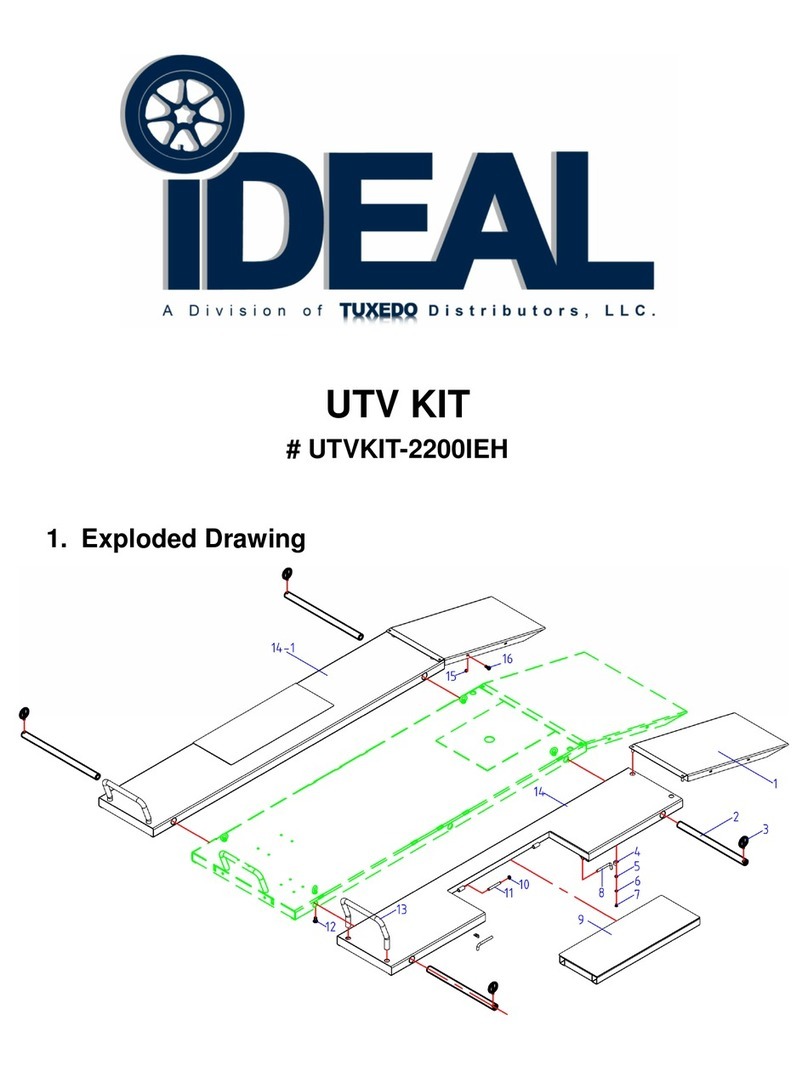
IDEAL UTV KIT User manual
Popular Lifting System manuals by other brands

McElroy
McElroy MegaMc PolyHorse Operator's manual

Böcker
Böcker TL 1512 operating manual

Scaleo medical
Scaleo medical Poweo 200 user manual

Genie
Genie Z-25/8 Operator's manual

Harmar Mobility
Harmar Mobility PARAGON OUTLANDER FULL Owner's manual & warranty information

WERTHER INTERNATIONAL
WERTHER INTERNATIONAL WML400Q manual