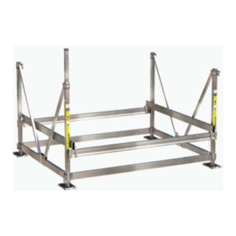
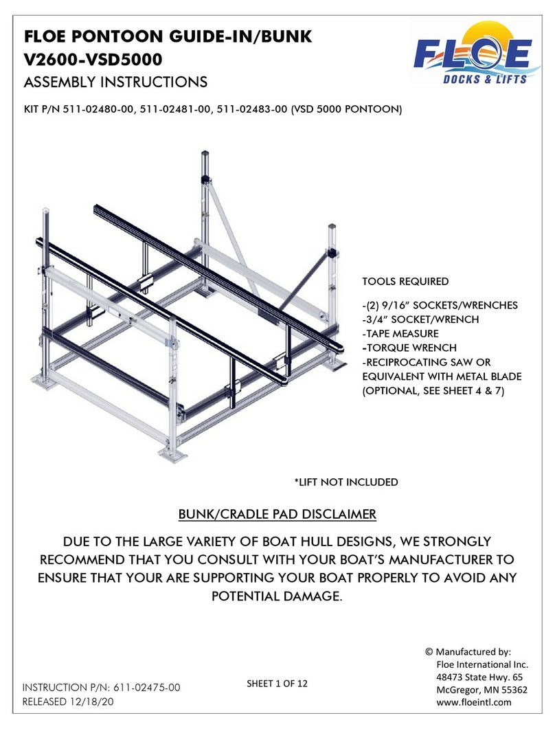
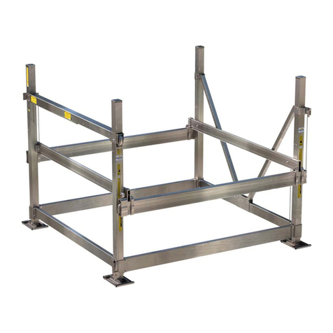
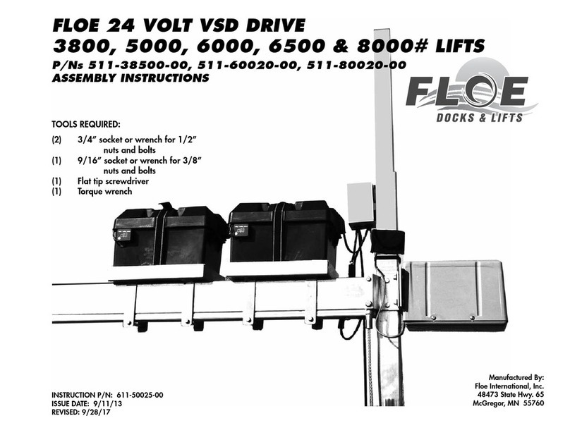
Floe V-2000 User manual

1
OWNER’S MANUAL
V-2000 V-2600
V-3600 V-4600
V-2602 PWC
Boat Lift Systems
Read and follow all safety rules and operating instructions
carefully before attempting to install or operate lift system.
ATTENTION ATTENTION ATTENTION
Visit our website at www.floeintl.com
Retain this manual for future reference
Watch our customized boat lift setup and installation video:
www.floeintl.com/manuals-information
manual winch or dc winch with electronic control system

2
Congratulations on the purchase of your new FLOE Boat Lift!
Like you, I enjoy many kinds of waterfront activities, and I know that to have fun I
need to keep my boat secure, protected, and accessible. Through my years of experi-
ence, I’ve learned how boat lifts should not only protect your watercraft investment,
but also be convenient and easy to use - and I have developed them accordingly.
The fact that you purchased a FLOE boat lift tells me that you research a product
thoroughly. You will nd a FLOE boat lift has many innovative features that will ensure
years of dependable service, satisfaction, and enjoyment.
Because your FLOE boat lift is engineered to lift and support a tremendous amount of weight, it is critical that you operate
it safely. Anyone who operates this lift must read the entire owner’s manual before operating the lift to make sure they are
able to operate it properly and enjoy all of its features to the fullest. See you on the water!
Wayne Floe , CEO - FLOE International
Letter from Wayne Floe .........................2
Important Safety Information .................3-4
Important Safeguards............................4
Certicate of Boat Lift Pre-Delivery .......5
Boat Lift Capacities................................6
Is your lift’s capacity adequate for your boat? ....7
Boat Lift Dimensional Specications .....8-10
Battery Selection & Charging Options...11
Winch Selection & Use..........................11
Charging the Battery..............................12
Assembling the DC Winch.....................12-13
Electrical Connection Panel & Limit Switch.........12
Connecting & Using Wired Remote.....................14
Connecting & Using Optional Wireless Remote..15
DC Winch Troubleshooting..................................16
Manual Winch........................................16
Raising/Lowering Main Cradle Lift Beams. 17
Leveling Boat Lift...................................18-19
Boat Lift Installation & Removal Options .. 20-21
Boat Lift Wheel Kits .............................................20
Cable & Pulley System........................................20
Float & Roll/Insta-Float........................................21
Full-Length Bunk Setup............................. 22
Cradle Pad Pivot Bunk System ................. 23
Pontoon Guide-In/Bunk System ................ 24
Carpeted Guide-In System........................ 25
Vertical Guide-in Selection & Adj............... 26
Boat Placement/Motor Stop....................... 26
Proper Canopy Frame Positioning ............ 27
Canopy Fabric Installation......................... 28
Canopy Wind Precaution........................... 29
Canopy Fabric Removal............................ 29
Canopy Fabric Folding Instructions........... 30
Canopy Fabric Care & Cleaning................ 30
Optional LED Floodlight............................. 31
Inspections & Maintenance ....................... 32-33
Boat Lift Exploded Views & Parts List ....... 34-49
Warranty & Registration ............................ 50-53
CONTENTS
It may also be benecial to view the lift portion of
FLOE’s marine video, “A Look Into FLOE Dock & Lift
Systems.” See it on our website in streaming video.
Please retain this manual for future reference

3
You will be killed or seriously injured if
you don’t follow instructions.
DANGER
IMPORTANT SAFETY INFORMATION
Your safety and the safety of others is very
important. We have provided many important
safety messages in this manual and on your dock
system. Always read and obey all safety messages.
If you do not understand any of these instructions,
please ask your dealer or call FLOE Customer Service at
218-426-3563 or toll free 800-336-6337.
This is the safety alert symbol.
This symbol alerts you to hazards
that can cause serious injury or
potential death to you and others,
plus damage to the dock system. All
safety messages will be preceded
by the safety alert symbol and the word “DANGER”,
“CAUTION” or “WARNING.”
You can be killed or seriously injured if
you don’t follow instructions.
CAUTION
Failure to take appropriate action could
result in mechanical failure, product
damage and/or cause serious injury or
potential death.
WARNING
All safety messages will identify the hazard and tell you how to reduce the chance of injury.
DANGER
Never allow anyone under this lift system,
especially while it is being operated, or it is
supporting the weight of a watercraft.
Stay clear of boat lift when someone if entering or
exiting the lift with a boat. Never try to assist the
boat’s direction while it is in motion (either from
inside or outside the boat).
Never work on or make adjustments to boat, boat
lift, or boat lift accessories while the lift is supporting
the weight of the boat.
IMPORTANT SAFEGUARDS
Read and follow all safety rules and
operating instructions carefully before
attempting to install dock system.
WARNING
CAUTION
While operating the lift, keep all body parts, long
hair, loose clothing, and jewelry away from all
moving parts, including (but not limited to) the
drive-train mechanism, cables, pulleys, and lift
platform.
Be sure the lift cradle is completely lowered
before any adjustments or repairs are made to
the winch.
Always keep all people clear of the boat lift sup-
port structure and lifting cradle. Never swim
or play near a boat lift, even if it’s not being
operated.
Make sure the boat lift is completely clear of
people or other obstructions prior to operating.
Do not operate a boat lift with people inside the
boat.
Never operate a boat lift with protective cover
removed from drive train system.
This manual includes the latest information at the
time it was printed. We reserve the right to make
changes in the product after that time without
notice. Keep this manual so it will be available
to who ever is using this product.

4
If the boat lift system is not assembled, installed, or operated properly, mechanical failure,
as well as serious injury or death, could result. See to it that all users understand
that this lift system is a piece of heavy equipment that requires the use of good
judgement and the knowledge of its dangers and limitations.
WARNING
Lift must be assembled and installed
properly or mechanical failure and possible
injury may occur.
Never overload a boat lift. See capacities/
specications for important information
regarding the boat’s actual weight and boat
lift capacity limitations.
Never operate a boat lift that is not level. Under
normal conditions a boat lift operates
under extreme force. When the lift is not
level, these forces are greatly multiplied
and bodily injury or damage to the lift can
result.
Perform all inspections and maintenance on
a regular basis. Replace any worn parts im-
mediately to avoid potential lift failure. Ensure
all pulleys are operating properly and that all
cables and their attach points are secure
and free of excessive wear and fraying. See
Inspections & Maintenance section for all
important details.
Bodily injury or damage to lift system
may result if installation or removal of this
lift is attempted without rst reading and
understanding the installation and removal
section of this manual.
If this unit is equipped with a canopy,
severe wind damage may occur if the lift is
not securely held down to the lake bottom
by screw anchors or by some other means.
FLOE lift systems have not been tested in
brackish or salt water conditions. Lift failures
due to installations in brackish or salt water
locations will not be covered by FLOE’s
warranty. FLOE will not be responsible for
incidental or consequential damages result-
ing from these installations.
Never install the lift system in a body of
water whereas either the rising water or
wave action will not always ow under the
main lift beam. For example, do not install
lift in bodies of water with signicant water
uctuation or large water bodies that have
excessive wave action.
This manual is intended to serve as an owner’s use and maintenance guide for a lift that has been
properly assembled by a qualied, trained professional. Detailed assembly instructions
are packaged with the lift systems.

5
Certicate of
Boat Lift Pre-Delivery
All dealers should have reviewed the checklist below with retail customers upon
purchase of a boat lift. If they did not cover this, retail customers must review
thoroughly and understand the statements below.
Date of Purchase ______/______/______ Boat Lift Model ______________________________________
Customer Delivery: Each item must be initialed by the selling dealer upon sale.
______ I understand that the boat lift must be properly assembled and must be tested prior to use with a boat.
______ I understand that a serious injury or death could occur if a boat lift is overloaded, not correctly assembled,
installed, maintained or not used properly.
______ I was given an owner’s manual and I promise to read and understand it before using the boat lift.
______ I understand that it is my responsibility to get clarication on anything in the owner’s manual that I don’t fullly
understand before using the lift system.
______ I understand that I must educate all persons who will be around or using my boat lift as to how to do so safely.
______ I understand that people must stay clear of the boat lift when it is supporting the weight of the boat. No one
should ever swim under it, be on it, in the boat, or in any position that could cause harm to them if the lift
were to suddenly drop.
______ I understand safe operation of the lift requires people to stay clear of moving parts and pinch points.
______ I understand that a boat lift should never be overloaded under any circumstance. A boats published dry
weight is usually substantially lower than its actual loaded weight. Your boat should be weighed with fuel,
water, batteries and contents in order to know its actual weight.
______ I understand the total capacity of the boat lift is equal to the combination load limit of the two main end lift
beams. For instance, a lift with a 5,000 pound capacity has a load limit of 2,500 per lift end beam.
______ I understand that a 5,000 pound total boat weight could easily over-load one of the main lift beams on a
5,000 pound capacity lift. For instance, if the boat was positioned so that one main lift beam supported 3,000
pounds and the other only supported 2,000 pounds, the lift would be over-loaded. For this reason, FLOE
recommends that your total loaded boat weight doesn’t exceed 85% of the lifts rated capacity and that you
locate and place the boat’s center of gravity (balance point) in the center of the two lift beams.
______ I understand that the boat lift needs to be installed level and must be kept level while it is in use. A lift that
isn’t level will have a reduced lifting capacity of 5% per 1” of being out of level.
______ I understand that I need to pull the drain plug on my boat if it is subject to water accumulation as this could
easily overload the boat lift.
______ I understand that I should never lift my boat if it has been swamped or has any signicant additional water
weight in it that will overload the boat lift’s capacity.
______ I understand that if my lift is equipped with a canopy it must be properly secured or it could blow over and
cause damage not covered under warranty.
______ I understand that I must discontinue using the lift immediately and contact my FLOE dealer if any unusual
sounds or functionality are present.
______ I understand I must follow all inspection and maintenance procedures as outlined in my owner’s manual.
Selling Dealership Name_________________________________________________________________________
Selling Dealership Signature_______________________________________________________________________
Print Name
Customer Signature_____________________________________________________________________________
Print Name

6
LIFT CAPACITIES
It’s recommended that the total loaded weight of
the water craft doesn’t exceed 75-85% of the to-
tal lift capacity. The total capacity of a lift is the
combined capacity of each of the boat lifts two
main lifting beams.
Never exceed the weight capacity of either main
lift beam. For instance a 5,000 lb capacity boat lift
is limited to 2,500 lbs for each main lift beam. It is
very easy for a 4,000 lb boat to exceed the capac-
ity of a 5,000 lb boat lift by not parking on the lift in
the correct position.
BEFORE PUTTING A BOAT ON THE
LIFT YOU NEED TO KNOW THREE
VERY IMPORTANT THINGS:
1. Determine the total loaded boat weight?
Weigh your boat loaded with fuel, water and ev-
erything in that you could ever have in it when it is
parked on the boat lift. Not all manufacturers pub-
lished boat weights are accurate because they
don’t account for motors, gear, fuel, water, etc.
2. Determine the boats center of gravity or CG?
A boat’s CG is the location under the boat hull
which the boat will balance if sitting on a narrow
object ((Illustration A). Your dealer or the manu-
facturer of the boat should be able to help you
locate the boat’s CG. Be sure that the motor and
gear weight have been taken into consideration.
Never exceed the lift’s rated capacity. Doing
so could cause structural/mechanical failure
and serious injury or death.
WARNING
3. Determine that the boats center of gravity (CG)
is centered between the two main lift beams
The boat should be parked so that the boat’s CG
or balance point is centered between the two
main lift beams (Illustration B). Each of the lift
beams should be supporting the same amount of
weight.
Once you know that your boat is well within the
boat lifts rated capacity and the location of the
boat’s CG develop a positioning method that will
ensure that all users of the boat lift will park with
the Boat’s CG in the center of the lift. Here are a
couple of suggestions to do this consitently:
• Use a motor stop.
• Note the proper location of the boat on the lift
and use some sort of marking system or labels.
• If equipped with canopy, center the canopy
over the boat when the boat’s CG is in the
center of the lift, park with the boat centered
under the canopy.
• You can even hang an object such as a
tennis ball so it just touches the windshield
when the boat is properly positioned.
If your boat is not positioned properly, you can
extremely overload one of the main lifting beams
(See Illustration C, below).
Illustration A: above shows the boat’s balance
point of center of gravity (CG).
x
Illustration B: shows the boat’s center of gravity
(CG) centered between the two main lift beams
– each of the lift beams is supporting the same
amount of weight.
Illustration C: shows a boat’s center of gravity
(CG) improperly positioned so that it extremely
overloads one of the main lifting beams.

7
HOW TO DETERMINE IF YOUR
LIFT’S TOTAL CAPACITY IS
ADEQUATE FOR YOUR BOAT
One way to determine whether the lift’s capac-
ity is adequate is to log onto FLOE’s website,
www.oeintl.com, and click on the Boat Lift
Selector program. This program will calculate opti-
mal boat positioning and guide you to the best lift se-
lection for your boat. It even has a link that will help
you determine the weight of your craft. Your dealer
can also assist you in making the best choice.
The following simple exercise is a second, but
less accurate way, to manually determine the lift
capacity needed for your boat:
1. Obtain the boat’s actual total weight including
motor, fuel, water, equipment, accessories, etc.
2. Subtract the weight of the motor and fuel from
this number.
3. Take the boat’s weight, (the result of step 2), di-
vide it in half and add the weight of the motor and
fuel to that number. This number is the approximate
weight that the rear lift beam will need to support.
4. Take this number and multiply by two. This will
equal the approximate minimum rated lift capacity
needed for the boat.
For instance: If the boat is an I/O that has a total
loaded weight of 2900 lbs. and the fuel, motor and
lower unit weigh approx. 800 lbs. it would be calcu-
lated as follows:
• 2900 - 800 = a boat only weight of 2100 lbs.
• 2100 / 2 = 1050 lbs. This is the approximate
boat weight that will be supported by each lift
beam (not including motor and fuel).
• 1050 + 800 = 1850. This is the approximate
actual weight that the rear beam will need to
support.
• 1850 x 2 = 3700. This is the minimum overall
boat lift capacity needed.
This example does not include any additional hard-
ware or accessories that would affect the capacity
needed.
If watercraft is open to the accumulation
of rain water, be sure boat’s drain plug is
pulled. Additional water weight may cause
the maximum lift capacity to be exceeded,
resulting in potential lift damage or bodily injury.
This is a guideline only. It is the operator’s responsibility to ensure capacities are not exceeded.
You must weigh your boat fully loaded,
including fuel, gear, etc. to get its accurate
weight. It is common for published dry weights
to be considerably lower than actual loaded
weights. Lift and/or boat damage due to
overloading is not covered by your warranty.
WARNING
WARNING
VSD-4600
Each lift beam has a total capacity of 2500 lbs and is
rated to support one-half of the lift’s total capacity.
MAIN CRADLE
LIFT BEAM 1
MAIN CRADLE
LIFT BEAM 2
Fig. 1

8
LIFT DIMENSIONAL SPECIFICATIONS - V2000, V2600, V2602, V3600, V4600
MODEL/
CAPACITY
WINCH
OPTIONS
BUNKS BED
TRAVEL
INSIDE
WIDTH
OUTSIDE
WIDTH
FRAME
LENGTH
V-2000 lb. 36” Crank
Wheel
Full Length Bunks 36” 96.5” 109” 97.5”
V-2602 lb. 36” Crank
Wheel
12 Volt DC
Full Length Bunks
(standard)
52” 116.5” 129” 66”
V-2600 lb. 48” Crank
Wheel
12 Volt DC
Pivoting Cradle Pads
Full Length Bunks
Pontoon Bunk Kit
52” 116.5” 129” 109.5”
V-3600 lb. 48” Crank
Wheel
12 Volt DC
Pivoting Cradle Pads
Full Length Bunks
Pontoon Bunk Kit
52” 116.5” 129” 109.5”
V-4600 ln. 48” Crank
Wheel
12 Volt DC
Pivoting Cradle Pads
Full Length Bunks
Pontoon Bunk Kit
52” 116.5” 129” 109.5”
Specications and models may change without notice
due to continuous improvements to our products
MODEL/
CAPACITY
LEVELING
LEG TRAVEL
TRAVEL WITH
EXTENSIONS*
CANOPY
OPTION
GUIDE-IN
OPTIONS
MAX INSIDE
WIDTH WITH
GUIDE-INS
WEIGHT
(Does not include
weight of winch
or accessories &
options)
V-2000 lb. 0 - 30” 28.5 - 50.5” 18’, 20’ double vertical
vertical
84.5”
82”
275 lbs.
V-2602 lb. 0 - 30” 28.5 - 50.5” 12’ vertical 102” 323 lbs.
(Includes weight of
standard bunks)
V-2600 lb. 0 - 30” 28.5 - 50.5” 20’, 22’,
24’, 26’
double vertical
vertical
horizontal with
vertical bumpers
104.5”
102”
318 lbs.
V-3600 lb. 0 - 30” 28.5 - 50.5” 20’, 22’, 24’,
26’, 28’
double vertical
vertical
horizontal with
vertical bumpers
104.5”
102”
372 lbs.
V-4600 ln. 0 - 30” 28.5 - 50.5” 22’, 24’,
26’, 28’
double vertical
vertical
horizontal with
vertical bumpers
104.5”
102”
414 lbs.
SEE FOLLOWING PAGES FOR DIAGRAMS
* Deep water extensions available. ** Does not include the weight of the bunks, guides, or other accessories.

9
9

10
10

11
WINCH SELECTION & USE
You can customize your FLOE vertical lift with the
winch style that best ts your needs and budget.
The DC battery-powered winch offers an effortless
way to raise and lower the cradle lift beams and boat
by simply pushing a button. Another option is the
manual winch. Although you supply the power with a
manual winch, FLOE’s gear-reduced winch system,
combined with a large crank wheel and speed knob,
makes it easy to raise and lower your boat.
DC WINCH WITH ELECTRONIC
CONTROL SYSTEM
With the DC Winch with Advanced Switch Control
(ASC) (Fig. 2), FLOE has combined the depend-
ability of a custom 12 Volt DC StrongArm winch
manufactured by Dutton-Lain-
son Company, and FLOE’s ad-
vanced electronic control system
to give you standard wired re-
mote lift operation and the option
of wireless remote lift operation.
With the DC Winch with ASC,
you can raise or lower your boat
by pushing the up or down
buttons on the standard wired remote pendant
(Fig. 3). The wired remote’s 30’ cord enables you to
place the winch opposite your dock, and still have the
controls within easy reach of your dock or boat.
With the purchase of the optional wireless remote
kit, the lift can be operated with a small hand-held
transmitter. This transmitter (Fig. 4) also operates
the interior light and optional oodlights. See pages
12 and 29 for more information on these optional
features.
SELECTING THE BATTERY
Before assem-
bling or using
the DC Winch
with Electronic
Control System,
you need to
select and pur-
chase a suitable
battery. The fol-
lowing sections
give you guide-
lines for selecting the correct battery, and keep-
ing it properly charged.
The recommended battery is a 12-Volt, deep-cy-
cle, Group 27 (case size), with 600 cold cranking
amps and stud post terminals with wing nuts (lead
top posts). An Interstate SRM-27 meets these cri-
teria. FLOE does not provide the battery.
Battery boxes include a
built in battery condition
indicator to let you know
the level of your charge.
If you are leaving your batteries in an unheated
area for seasonal storage, ensure they are fully
charged according to the manufacturer’s instruc-
tions. If the batteries are left on the lift, unplug the
wireless remote to ensure it does not drain the
batteries.
When charging batteries, it is important
to follow the manufacturer’s instructions
for both the battery and charging
systems to ensure that batteries are not
damaged by improper or over-charging.
WARNING
Batteries that are improperly connected can
cause damage to the lift system, batteries,
and may cause a potential explosion.
WARNING
Fig. 2 Advanced Switch Control with DC Winch
Fig. 3 Wired Remote
Fig. 4
Fig. 5

12
CHARGING THE
BATTERY
In order to achieve peak
lift performance and max-
imum battery life, the bat-
teries must be properly
charged and maintained.
If the batteries are run
down or faulty, the lift sys-
tem will either move
very slowly or not at all.
Battery boxes include a built in battery condition
indicator to let you know the level of your charge
(Fig. 5).
Two Charging Options:
Option #1: Access the battery posts and charge
the battery as you would normally. Charge the
battery per manufacturer’s instructions for both
the battery and the charger.
Option #2: To maintain a battery charge with the
optional FLOE 12-Volt solar panel (Fig. 6). mount
panel per included instructions and wire it to the
battery as shown in Fig. 7. Be sure the panel faces
the sun during peak daylight hours. A solar panel
provides continuous charging on sunny days.
NOTE: Solar panels will only maintain a charge
on batteries. Be sure batteries are fully charged
before installing a solar panel.
SEASONAL STORAGE
There is no need to cover the DC winch for winter
storage. If you choose to do so, do not close or seal
the bottom of the cover as this will trap moisture and
encourage internal corrosion.
For battery care, disconnect the ring connectors and
fully charge the battery according to manufacturer’s
instructions.
Fig. 7
Solar Panel
& Battery
Diagram
Fig. 6
All battery and motor connections must be corrosion
free and tight. If not maintained properly, excessive heat
will be generated which can melt the connections.
WARNING
CONNECTING THE BATTERY
The Advanced Switch Control (ASC) with DC Winch
comes standard with an aluminum battery tray, plastic
battery box, and the cabling to connect the battery to
the electronic control panel. Attach the ring connec-
tor on the red power cord with the automatic overload
circuit breaker to the positive side of the battery, and
the black cord to the negative, as shown in Fig. 8.
The circuit breaker will trip if an excessive amount of
current is drawn through it. If this occurs, refer to the
section on Troubleshooting the DC Winch on page 15
of this manual.
ASSEMBLING THE DC WINCH WITH
ADVANCED SWITCH CONTROL
Instructions for assembling the DC Winch with ASC
are packaged with the winch. Refer to those instruc-
tions for detailed, step-by-step procedures for attach-
ing the battery tray; installing the winch, eyebolt and
lifting cable; attaching the magnet holders, and locat-
ing the wired remote. The following sections will give
a brief overview of the electrical connection panel,
how to connect the limit switch and its purpose, how
to use the wired remote, and general lift operation
methods. Refer to your instructions for additional in-
formation. Please read all warnings carefully.

13
DC WINCH
ADVANCED
SWITCH
CONTROL
(ASC)
The ASC is de-
signed to allow for
easy hook up of
standard and op-
tional components.
Proper hook up to
the panel will be
addressed as each
component is cov-
ered in this manual.
LIMIT SWITCH CONNECTION AND
IMPORTANT INFORMATION
The DC Winch ASC is equipped with an automatic
upper magnetic safety limit switch. The two prong
connector for the limit switch assembly plugs into the
two prong connector on the Advanced Switch Contol
box. The magnets for the limit switch are housed in
two aluminum tubes. The rst of these tubes, which
contains the limit switch, is mounted to the inner side
of the winch corner post, approximately 6” below the
upper clamp as shown in Fig. 11. The second magnet
holder is attached to the top of the side cradle beam
(ush with the outside edge) in line with the corner
post and limit switch. When the cradle is raised, as
the magnet holder on the cradle beam passes the limit
switch on the corner post, the magnetic force triggers
the switch. Fig. 12. Once a limit switch is triggered,
it prevents the winch from raising the cradle bed be-
yond its normal travel limit. Exceeding this limit will
cause severe damage to the winch or lift.
Submerging of the electronic components
including the electric motor in water may cause
lift failure that is not covered by warranty. When
properly installed, the wave action will ow under
the main lift beams and not break against them.
This will ensure that the integrity of the lift frame
and electrical system will not be compromised.
WARNING
IMPORTANT INFORMATION
& GENERAL MANITENANCE
• When used on a Floe Vertical Boat Lift, this winch
must be properly assembled with two pulley blocks
and a triple-line cable system. Any other assembly
would greatly reduce the winch/cable capacity and is
not recommended.
• Maximum winch capacity, with two pulley blocks and
triple-line cabling, is 4600 lbs.
• For use on FLOE V-2000 - V-4600 lift models.
• It is normal to hear cable noise, such as pinging and
popping, as the winch is lifting the boat.
• The winch will smell hot until the brake is broken in.
(See label on control box for additional information.)
Periodically check the drum of the winch, (the cylinder
that the lifting cable winds onto), by lowering the cra-
dle lift platform so that most of the cable is unwound.
Visually inspect the drum for any excessive wear,
or channeling. See the section on Inspections and
Maintenance on pages 29 to 32 of this manual, for
more information about how to inspect and maintain
the cables on the lift and the gears of the DC winch.
• Grease the cable and the winch gears annually.
• This winch will smell hot and may smoke during the
friction brake’s break-in period.
• This winch is intended for intermittent use only. Con-
tinuous running in excess of three minutes can dam-
age winch motor. After maximum run time the motor
must cool for a minimum of ve minutes.
• Additional information for winch operation is located
on the electronic control.
The safety limit switch assembly must remain
intact and working properly or damage may
occur to the DC Winch With Electronic Control
System and the boat lift.
WARNING
Fig. 11 Limit Switch Placement
Fig. 12 Magnetic Holder
Attachment
SEE WARNING ON
PAGE 17.
LIMIT
SWITCH
6”

14
WARNING
When raising your lift the winch cable must wrap around
the drum from the inside to the outside or severe damage
to winch and it!s brake system may occur. It may also
cause your boat to slowly lower to the water. If your winch
is wound up backwards, simply lower the lift and continue
running the winch until the lift platform raises.
CONNECTING AND USING
THE WIRED REMOTE
The DC Winch with A d v a n c e d
System Control (ASC) comes stan-
dard with a wired remote control. T h e
remote plugs into the 10” ASC cord
with a blue ring. If the plug is not
installed properly, the lift will not oper-
ate. To raise the lift, simply press the
“Up” button, to lower the lift press the
“Down” button. (Fig. 15). The lift will
stop automatically when it reaches
the end of its up travel limit or when
the button is released. Never rely
completely on the limit switch. Read the warnings on pages
16-17 and the “Stop Here” section on page 17.
The corded remote has a 3-position key switch. The key
is removable from all positions. OFF position disables the
wired and wireless remotes. ON position provides wired
and wireless power with the key in or out. In the WIRE-
LESS position, only the wireless remote will work with the
key in or out.
The wired remote is weather resistant but not waterproof
and should not be exposed to the elements. Installation
under a canopy system is recommended. If the remote is
not covered by a canopy, unplug and store indoors when
not in use. Turn the wired remote to the off position while
storing the lift to ensure power is not beng drawn from the
battery durng the off season. NOTE: If the remote is acci -
dentally submerged in water, to avoid corrosion on the con -
tacts, it should be taken apart
and blown out until dry.
If the lift is equipped with a
canopy system, the cord on
the remote should be
attached with Velcro one-
wrap to the canopy upright
tube and the canopy hoop .
Then run the cord forward
from the frame!s midpoint,
or completely across the
hoop, so that the pendant
can be located for easy
access from either the boat
or the dock. (Fig. 16). Refer to the assembly instructions
packaged with the winch for details.
NOTE: If the lift is not equipped with an optional
canopy system for routing the wires to the dock side
and it does not have the wireless remote option, the
lift system should be installed so that the electrical
connection panel is next to the dock.
VELCRO
REMOTE
PENDANT
Fig. 16 Velcro One-Wrap
Fig. 15 Wired
Remote
The magnet holder on the cradle beam must remain
intact and must be checked periodically. There should be
no more than 1/2” gap between the inner edge of the side
cradle beam and the corner post when the lift bed is shift-
ed away from the corner post. If there is more than 1/2”
gap, adjust the side cradle beam toward the corner post.
(See your boat lift assembly instructions.)
WARNING
Do not operate winch without reading and understanding
this warning and all other warnings on this lift and in the
owners manual. (1) Do not exceed the winch!s rated
c a p a c i t y. (2) Inspect the winch cable often to ensure it is
not frayed. Replace as necessary. (3) Inspect the winch
gears often to ensure they are not dangerously worn.
Replace as necessary. (4) Grease the cable and the
winch gears annually. (5) Do not rely on the safety limit
switch to stop the upward bed travel.
WARNING
DC WINCH ROTAT I O N
When using a DC winch the winch drum must always rotate
from the inside to the outside when raising your boat. When
wound correctly, the cable will go up the back of the winch,
or the side closest to the corner post on which it is mounted.
If the cable is wound
the wrong direction
on the drum of the
DC winch, the weight
on the lift will fight the
brake, so that the
cradle lift beams may
slowly lower, drop-
ping your boat gradu-
ally back into the
w a t e r. To correct
this, simply use the
wired remote to
lower the lift and let it
continue to run until
the lift cradle beam
raises again.
Fig. 13
14
CONNECTING AND USING THE WIRED
REMOTE
The DC Winch with Advanced
System Control (ASC) comes
standard with a wired remote
control. The remote plugs into
the 10” ASC cord with a blue
ring. If the plug is not installed
properly, the lift will not oper-
ate. To raise the lift, simply
press the “Up” button, to lower
the lift press the “Down” button.
(Fig. 15). The lift will stop auto-
matically when it reaches the
end of its up travel limit or when the button is released.
Never rely completely on the limit switch. Read the
warnings on pages 16-17 and the “Stop Here” section
on page 17.
The corded remote has a 3-position key switch. The
key is removable from all positions. OFF position dis-
ables the wired and wireless remotes. ON position
provides wired and wireless power with the key in
or out. In the WIRELESS position, only the wireless
remote will work with the
key in or out.
The wired remote is
weather resistant but not
waterproof and should
not be exposed to the
elements. Installation un-
der a canopy system is
recommended. If the re-
mote is not covered by a
canopy, unplug and store
indoors when not in use.
Turn the wired remote to
the off position while stor-
ing the lift to ensure power is not beng drawn from the
battery durng the off season.
NOTE: If the remote is accidentally submerged in wa-
ter, to avoid corrosion on the contacts, it should be
taken apart and blown out until it is dry.
If the lift is equipped with a canopy system, the cord
on the remote should be attached with Velcro – one
wrap to the canopy upright tube and the canopy hoop.
Then run the cord forward from the frame’s midpoint,
or completely across the hoop, so that the pendant
can be located for easy access from either the boat or
the dock (Fig. 17). Refer to the assembly instructions
packaged with the lift for details.
NOTE: If lift is not equipped with an optional cano-
py system for routing the wires to the dock side and
it does not have the wireless remote option, the lift
system should be installed so that the electrical
connection panel is next to the dock.
Fig. 16
Wired
Remote
Fig. 17
Velcro
Remote
Pendant

15
CONNECTING AND USING
OPTIONAL WIRELESS REMOTE
An optional
wireless remote
control (Fig. 18)
will allow op-
eration of the
lift from a dis-
tance. This re-
mote includes a
receiver, mount-
ing post and two
wireless trans-
mitters. The
wireless remote plugs into the 7-in. yellow plug
on the ASC.
For more details, see the assembly instructions.
Should the remote fail to perform properly these
brief steps will help to diagnose the problem.
1. Lift moves without buttons pushed. Unplug the
wireless remote and remove the batteries from
the transmitter. Plug the radio remote receiver
back in, and if the lift still moves, it is possible
that the wireless receiver unit is faulty. If the lift
does not move, replace the batteries in the trans-
mitter to determine if it was transmitting when it
should not have been. Leave the battery out of
any transmitter determined to be faulty and con-
tact your dealer.
2. Lift will not move when the transmitter button is
pushed. Check to ensure that the batteries in all
transmitters are good. If a transmitter has been
dropped in the water, dry it out or replace it. If the
problem persists, it may be due to radio interfer-
ence in your area. When there are two remotes
and both are transmitting at the same time, one
signal will cancel out the other, even if the second
transmitter is for another lift.
Never allow anyone on or under this lift
system, especially while it is being operated
or supporting the weight of a watercraft.
DANGER
Fig. 18
It is important that you never raise or lower
the lift using the wireless remote until
you are sure no one is on or near the lift.
WARNING
RAISING AND
LOWERING LIFT
MANUALLY
If there is no power to the
DC winch, the lift bed can
be manually lowered with
the emergency handcrank
packaged with the winch.
Make sure battery power
to the lift is disconnected
before attempting to lower
or raise the cradle lifting platform manually.
Remove the plug on the side of the winch
housing and insert the crank handle (Fig. 20).
Turn counterclockwise to lower the lift. Continue
turning until the cradle is fully lowered and there
is slack in the cable. Turning clockwise will raise
the lift.
If the lift should raise or lower by itself without
operating the remote control, disconnect the
battery cable ring connectors immediately, if
you are able to do so with-out the risk of injury
Contact your local dealer or FLOE International.
WARNING
Make sure battery power to the
DC winch is disconnected before
attempting to lower or raise lift manually.
WARNING
OPTIONAL LIGHTING KITS FOR
DC WINCH SYSTEMS
See page 30 for information about the optional
oodlight kit. Purchase of the optional wireless
remote system and a canopy system are required
for ood light kit to work properly.
CONNECTING AND USING
OPTIONAL WIRELESS REMOTE
An optional wireless
remote control (Fig. 17)
will allow operation of the
lift and LED floodlight from
a distance. This system
includes a wireless trans-
mitter and two key fob
remotes. Plug the wireless
cord into the 7” cord with
yellow ring on the
Advanced System Control
(ASC) panel (Fig. 18).
Then attach the combination receiver to the post. See
assembly instructions for more details.
Should the remote fail to perform properly, contact your
dealer for assistance.
You may also refer to the
troubleshooting section
of the instructions for
more suggestions and
information on how to
code your transmitter.
These brief steps will
help to diagnose the
problem.
1. Lift moves without buttons pushed. Unplug the
wireless remote from the Advanced System Control
(ASC) panel and remove the batteries from the hand-held
transmitter. Plug the radio remote receiver back in, and if
the lift still moves, it is possible that the wireless receiver
unit is faulty. If the lift does not move, replace the batter-
ies in the transmitter to determine if it was transmitting
when it should not have been. Leave the battery out of
any transmitter determined to be faulty and contact your
dealer.
2. Lift will not move when the transmitter button is
pushed. Check to ensure that the batteries in all trans-
mitters are good. If a transmitter has been dropped in the
water, dry it out or replace it. If the problem persists, it
may be due to radio interference in your area. When
there are two remotes and both are transmitting at the
same time, one signal will cancel out the other, even if the
second transmitter is for another lift.
The transmitter uses a lithium 3V watch battery, available
through your dealer, Part 511-00831-00. (Sony CR2032)
WARNING
It is important that you never raise or lower the lift using
the wireless remote until you are sure no one is on or
near the lift.
WARNING
If the lift should raise or lower by itself without operating
the remote control, disconnect the battery cable ring
connectors immediately, if you are able to do so with-
out the risk of injury. Contact your local dealer or
FLOE International.
Fig. 17 Optional
Wireless Transmitter
Fig. 18 4-Prong Wireless
Remote Connection
RAISING AND LOWERING
LIFT MANUALLY
If there is no power to the
DC winch, the lift bed can
be manually lowered with
the emergency hand
crank packaged with the
winch. Make sure bat-
tery power to the lift is
disconnected before
attempting to lower or
raise the cradle lifting
platform manually.
Remove the plug on the
side of the winch housing
and insert the crank han-
dle (Fig. 20). Turn coun-
terclockwise to lower the
lift. Continue turning until
the cradle is fully lowered and there is slack in the cable.
Turning clockwise will raise the lift.
WARNING
Make sure battery power to the DC winch is disconnected
before attempting to lower or raise manually.
Fig. 20 Emergency Crank
O P T I O N A L LIGHTING KITS FOR
DC WINCH SYSTEMS
See page 30 for information about the optional floodlight
kit. Purchase of the optional wireless remote system and
a canopy system are required for flood light kit to work
p r o p e r l y.
15
Fig. 18

16
DC WINCH TROUBLESHOOTING
A. Lift won!t go up or down
1. Check to see if the key on the wired remote is turned to
the ON position.
2. Check battery(s) condition and that it is properly charged.
Each battery should have between 12.7 and 13.8 volts.
3. Check to see that all battery connections are corrosion
free and tight.
4. Check plug connections from the Advanced Switch
Control (ASC) going to limit switch and remote(s) to
ensure they are plugged in properly and making positive
contact.
5. Check the wire connections from the Advanced Switch
Control (ASC) to the motor to ensure they are corrosion
free and making positive contact. Connections are locat-
ed under the motor cover.
6. Check auto reset circuit breaker or fuse. If the breaker
has tripped it should reset after a couple of minutes when
it cools down. If not sure it is working, you can bypass it.
•If circuit breaker has tripped or fuse is blown chances
are the motor is drawing too much current and it could
blow the fuse or trip the breaker again. Check the follow-
i n g :
a. Is the lift overloaded or has it exceeded its max
run/cycle on time
b. Is the brake improperly engaged
•With the winch units, the brake will drag if the cable
is wound up backwards on the drum. Refer to decal on
winch corner post.
•With VSD drive units, if the brake is not releasing
while in operation it will drag and cause the drive to draw
excessive current. You should hear the brake “click” on
the outside end of the VSD power unit box when raising
or lowering the lift.
c. Additionally there may be something causing fric-
tion in the system, such as a problem in the drive train, or
the cable/pulley system has an issue.
B. Lift will only work in one direction
If this occurs, you may have a problem with the end of
travel limit switch(es).
1. Test the end of travel limit switch(es) by using the limit
switch bypass plug located in the tool pouch.
2. To do this, un-plug the limit switch plug going into the A S C
and replace it with the bypass plug.
3. If the cradle is up, press the down button and vice versa.
4. Use extreme CAUTION. When using the bypass plug the
limit switches will no longer shut down the lift when it
reaches the end of its travel. This means you must NOT
run the lift either all of the way up or down.
5. When going up, stop short of the “Stop Here” decals
located on the corner post.
6. When going down, stop as soon as the cradle stops mov-
ing.
See page 29-30 for additional information.
FLOE has matched a winch and cable pull style to each
lift model to assure optimal performance. The V2000 lift
uses the 2500 DLB model winch with a double-pull cable.
“Double-pull” indicates that the winch cable goes through
a pulley-block and then directly back up to the winch
drum. This increases the winch!s capacity and decreases
the amount of effort you must supply.The V2600 lift takes
the B3500 winch and has a single-pull style cable.
Because the winch on this model is more powerful than
required, there is no need for a pulley-block. The V3400
and V4200 model lifts also use the B3500 model winch
with a double-pull cable setup.
MANUAL WINCH CRANK WHEEL
FLOE includes a “big wheel” with a speed knob attach-
ment that makes using the manual winch easy.(Fig. 21)
The V2000 & V2002 lifts come with a 36” wheel, while the
V2600 through V4200 models are packaged with 42”
wheels. These large-diameter wheels dramatically
reduce the amount of effort that a regular crank handle
would require to raise or lower the boat. The speed knob
is easy to grasp and allows you to turn the wheel with one
hand.
MANUAL WINCH OPTION
FLOE offers manual winches for the V-2000 through V-
4200 lift models. (Fig. 21) The brake style winch is man-
ufactured by Dutton-Lainson. It operates by maintaining
pressure on the brake
pad any time the
winch is being
cranked to raise the
cradle lift beams. As
the “dog” catches
each cog of the
sprocket, you will hear
a clicking sound. This
indicates that the
brake is working prop-
e r l y, and that the
drum is turning while
the brake prevents
the cable from
unwinding uncontrollably. When you “back the wheel off”
by turning it in a counterclockwise direction, the pressure
on the brake is reduced, allowing the smooth lowering of
the cradle lift beams and boat.
Fig. 21 Crank Wheel
With Speed Knob
WARNING
When raising lift a clicking sound should be heard indicat-
ing proper rotation and brake function. If no sound is
heard a fast uncontrollable spin-down could occur.
Attempting to stop the crank wheel during an uncontrol-
lable spin-down could result in severe injury.
16

17
Fig. 14a: Properly Leveled Lift in Adequate Water
Depth (no friction from hull hitting bunks).
Fig. 14b
Lift Platform has not been raised sufciently.
Water is hitting the rear cradle lifting beam.
DO NOT let cradle lift beam act as a wave-break!
Waves or spray
from waves
should not hit
motor. Warranty
is void if motor
is covered with
water
The main cradle lift beams should never act as a
wave-break. Make sure that the cradle lift platform is
always either raised high enough so that the waves
pass under it, or lowered completely beneath the
water. Waves breaking against the cradle lift beam
will cause unnecessary wear on the lift’s frame.
WARNING
Keep all body parts and clothing away from
cables and moving parts. Do not attempt to
stop the wheel if an uncontrollable spin-down
should occur.
WARNING
RAISING AND LOWERING
THE MAIN CRADLE LIFT BEAMS
Before raising or lowering the main cradle lift
beams, it is important that you understand how
to operate the remotes, what to do should the
remotes fail, and how to ensure that the lift is
both level and in adequate water depth. Please
read the safety statements and information in this
section carefully before connecting power to the
lift and operating it for the rst time. If the lift is
equipped with a canopy, it is important to stop
raising the boat before it or or any accessories
make contact with the canopy frame or fabric.
NOTE: Many boats have plug-in style bow and
stern lights that while plugged in are higher than
the rest of the boat. Be sure these are removed
when entering or exiting the lift or lowered prior to
lifting the boat to its normal raised position.
When the main cradle lift beams are in their low-
ered position on a properly leveled lift in adequate
water depth, the boat oats free of the bunks as
it enters or leaves the lift. (See Fig. 14). When
determining required water depth, take wavy
conditions into consideration. There should be
no chance of the boat hull lifting up on a wave
and dropping down onto the bunks. Guidance on
bunk placement is addressed in more detail on
pages 17 & 18.
To maintain the optimum water level for proper lift
operation, the minimum water depth is 31” and
the maximum is 81” for the VSD 7500 & 10,000
models. And a minimum of 29.5” with the maxi-
mum of 69” for all other vertical and VSD lifts.
Never work on or make adjustments to
boat, boat lift, or boat lift accessories while
the lift is supporting the weight of the boat.
DANGER
Stay clear of boat lift when someone is entering or
exiting the lift with a boat. Never try to assist the
boat’s direction while it is in motion (either from
inside or outside the boat).
DANGER
The operator should always watch the lift bed and stop
before exceeding the stop limit and “Stop Here” decals.
Failure to do so can result in serious bodily injury.
DANGER

18
INSTALLING AND LEVELING LIFT
E A S Y LEVEL™ LEVELING LEGS
( p a t e n t e d )
The FLOE V-2000, V-2002, V-2600, V-3400, and V-4200
lifts come standard with FLOE!s exclusive Easy-Level™
Leveling Leg. With the Easy-Level
TM
legs you can effort-
lessly raise, level, or lower the lift frame without getting in
the water.Also, these legs allow for easy adjustment if
the lift should settle or if the water level fluctuates meas-
urably.
As you prepare to install and level the lift, keep in mind
how crucial it is to prevent a boat hull from rubbing or hit-
ting the bunks or lifting beams and causing undue pres-
sure on the lift frame. Read the warning below, and refer
back to Fig. 22, which diagrams a properly leveled lift in
adequate water depth.
When positioning the lift it is important that it is placed in
adequate water depth (F i g . 22 on page 14). The cradle
must be lowered far enough for the boat to easily float on
and off without touching the lift bunks. If the boat hull rubs
on the bunks when entering or exiting the lift, the hori-
zontal forces can cause severe damage to the lift and will
void the warranty on affected components.
WARNING
WARNING
Never adjust leveling legs (up or down) with a boat on the
lift. The added weight of the boat will apply extreme pres-
sure to the adjustment system causing potential mechan-
ical failure and/or serious bodily injury.
VERTICAL LIFT - CABLING
As its name indicates, the vertical lift!s cradle beams raise
and lower vertically, or straight up and down, as opposed
to the pivot or cantilever style lift which has a cradle that
pivots back from the main frame. The advantage of the
vertical lift style is that the cradle lift beams drop lower,
thus requiring less water depth to float the boat onto the
lift and the cradle lift platform also raises your boat much
higher for greater protection. The winch cable winds or
unwinds onto the winch drum which raises or lowers the
lift. One end of the front leveling cable attaches to the
front corner post leg, passes over a sheave inside the
front cradle beam, through the beam itself, and then
under a sheave at the opposite end of the front cradle lift
beam. The cable is attached at its opposite end near the
top of the other front corner post. As the winch cable rais-
es or lowers the lift, the pulleys allow the cradle platform
to travel up and down along the leveling cables. The front
leveling cable, working with two corresponding cables in
the side cradle beams, keeps the cradle platform both
square as it travels up and down.
With the exception of the winch cables, all of FLOE!s ver-
tical lift cables are made of aircraft-quality stainless steel.
Because stainless steel cables are not flexible enough to
wind on a winch drum, FLOE uses the highest aircraft-
quality galvanized cables available for the winches.
WARNING
Do not raise the cradle lift beam platform beyond the “Stop
Here” arrow decal on the corner post of the lift frame.
Exceeding the maximum height can cause severe damage
to the corner post and lift frame, winch, and cables, as well
as your boat and accessories. See Fig. 24.
PROPER HEIGHT
“STOP HERE” DECAL
Never exceed the recommended height when raising the
lift. A“Stop Here”
arrow decal is
located on the
winch corner post
(See Fig. 24). It
is especially
important to
remember this
when using a
DC winch
because, if there is a limit switch failure, the winch will
continue to try to raise the boat. Going beyond the rec-
ommended height can cause damage to the winch,
cables, accessories, or lift frame.
Fig. 24
“Stop Here” Decal
18
LEVELING BOAT LIFT
INSTALLING AND LEVELING LIFT
EASY LEVEL™ LEVELING LEGS
(PATENTED)
FLOE lifts come standard with FLOE’s exclusive
Easy-LevelTM Leveling Leg. With the Easy-
LevelTM legs you can effortlessly raise, level, or
lower the lift without getting in the water. Also,
these legs allow for easy adjustment if the lift
should settle or if the water level uctuates
measurably.
As you prepare to install and level the lift, keep in
mind how crucial it is to prevent a boat hull from
rubbing or hitting the bunks or lifting beams and
causing undue pressure on the lift frame. Read
the warning below, and refer back to Fig. 14a on
page 13, which diagrams a properly leveled lift in
adequate water depth.
To raise or lower the lift frame, simply turn the
nut inside the leg as shown in Fig. 24. Turning
clockwise will raise the lift, counterclockwise will
lower it. Use a 3/4” socket with a socket wrench or
a 14 volt (or larger) cordless drill (Fig. 26) to ad-
just. Each of the four legs adjusts independently
so the lift can be perfectly leveled. As the lift is
raised or lowered, alternate among all four legs
When positioning the lift it is important that it
is placed in adequate water depth (Fig. 14a
on page 11). The cradle must be lowered
far enough for the boat to easily oat on
and off without touching the lift bunks. If the
boat hull rubs on the bunks when entering
or exiting the lift, the horizontal forces can
cause severe damage to the lift and will
void the warranty on affected components.
WARNING
WARNING
Never adjust leveling legs (up or down)
with a boat on the lift. The added weight
of the boat will apply extreme pressure to
the adjustment system causing potential
mechanical failure and/or serious bodily injury.

19
For leveling leg adjustment range, see boat lift
specications, page 5. The decal pictured in Fig.
24 and 25 has a useful measuring tape so that
you can see the water level on each corner post.
It is important that the water level reads the same
on all four corner posts. Once you determine what
leg extension measurement works best for your
boat and lift, you can use a waterproof marker
to draw a line at that point on the tape of one
corner post. This will be very helpful in following
seasons, either for you or especially for a hired
installer who may be unfamiliar with your boat,
shoreline, and lift.
after 1-1/2” to
2” of adjust-
ment – similar
to tightening lug
nuts on a tire
rim. If the drill
is working too
hard, you are
lifting too much
on an individual
leg and need to
proceed to the
other legs.
Fig. 24 Fig. 25
Drill will come to a sudden stop when leg is
fully extended or retracted. When approaching
the end of the leg’s travel, reduce the
speed of the drill. This will prevent you from
twisting your wrist or accidentally dropping
the drill. Do not use an impact wrench to
adjust as this will cause damage to the lift.
WARNING
Fig. 27 Fig. 28
Fig. 29
Fig. 26
Cordless Drill with
Socket Attachment
The 3/8” drive socket
adapter bit shown in inset
photo, along with a 3/4”
socket, will allow you to
use a cordless drill on the
leveling nuts to lower or
raise the lift’s legs.
FLOE TOOL KIT
FLOE has provided a kit with four tools for use
with your VSD boat lift.
1. Flush Style Grease Gun Tip (Fig. 27)
(for greasing the ball-screw mechanism)
2. 3/8” Drive Socket Adapter Bit (Fig. 28)
3. Limit Switch Bypass Test Plug (Fig. 29)
(See VSD Diagnostics on page 26 for
instructions on how to use the byass plug.)
The Velcro backed tool kit can be attached to the
lift frame, so that these tools are readily available
when needed. The kit is made from solution dyed
polyseter and has a fold-over ap to help protect
these adapters from the elements.
To attach the tool kit:
Remove the adhesive protective paper from the
back of the vinyl pouch and place the tool kit on
the corner post as shown, see Fig. 30. Now the
tools will be easy for you or an installer to locate.
Place tool
kit here
Fig. 30
Never operate a boat lift that is not level. Under normal
conditions a boat lift operates under extreme force. When
the lift is not level, these forces are greatly multiplied and
bodily injury or damage to the lift can result.
WARNING
Be sure people and objects are clear of the lift
and the leveling leg during adjustment. As the
lift is leveled, the entire lift frame will move,
causing the potential creation of pinch points
between the lift and dock system as well as
the sand pad and lake bottom.
WARNING

20
BOAT LIFT INSTALLATION
& REMOVAL OPTIONS
If the lift is in a climate where the lakes freeze dur-
ing the winter months, it may need to be installed
and removed on a seasonal basis. FLOE has
several accessory options designed to make this
easier. With the exception of the boat lift wheel
kit system, these options will be mentioned only
briey. Detailed assembly and use instructions
will be packaged with the lift accessories.
BOAT LIFT WHEEL KITS
If the lift is in a location where it can be rolled
straight in and out, we recommend using two pair
of optional wheel kits (Fig. 31). Attach wheel kits
to lift frame according to wheel kit assembly
instructions included in your boat lift wheel kit.
To install the lift with the optional wheel kits in place:
1. Raise the leveling legs so they are fully re-
tracted with a 14 volt (or larger) cordless drill or
wrench and 3/4” socket.
2. Once the weight of the lift is supported by the
wheels, roll the lift into position by hand, or pull it with
a boat using a “Y” cable harness. (Fig. 32 & 33)
3. Once the lift is in place, use a drill or wrench to
lower the leveling legs until the lift is level and the
wheels are off the bottom.
Boat Lift Wheel Kit
Two Pairs Shown
Raise 2”
Fig. 31
Fig. 33
Fig. 32
Lift being pulled into lake by boat
- OR- being pulled into shore by ATV to remove.
Do not attatch anything to pull from here.
CABLE & PULLEY SYSTEM
Boat lift wheel kits can be combined with the
optional Cable & Pulley System to enable you
to harness the power of a boat alone, or use in
combination with an ATV, winch, or other similar
means, to install and remove your lift. This sys-
tem consists of “Y” harness cable assemblies,
which can be added to each side of the lower lift
frame (Fig. 33).
The “Y” harness will distribute the weight on the
frame of the lift, so that you can then attach a
cable, chain, or rope of appropriate length from
the harness to your power source and pull the lift
without damaging it.
The wheels must not touch the lake bottom
once the lift has been installed. The weight
of the boat and lift must be supported by the
sand pads only.
WARNING
Never tie a rope, chain or cable to the center
of a lift’s frame beam. This can bend or break
the beam. Always use a “Y” cable harness
set-up to more equally distribute the pressure
on the frame.
WARNING
Other manuals for V-2000
2
This manual suits for next models
4
Table of contents
Other Floe Lifting System manuals
Popular Lifting System manuals by other brands

morse
morse 185A-HD Operator's manual

Stratus
Stratus SAE-C10XE Installation, operation & maintenance instructions

AGT INDUSTRIAL
AGT INDUSTRIAL AGT-B1000 product manual

Hallins
Hallins Reflex 200 instruction manual

maxilift
maxilift M50 Series Use and maintenance manual

ASEplatinum
ASEplatinum TP12KFX ASSEMBLY & OPERATION INSTRUCTION MANUAL