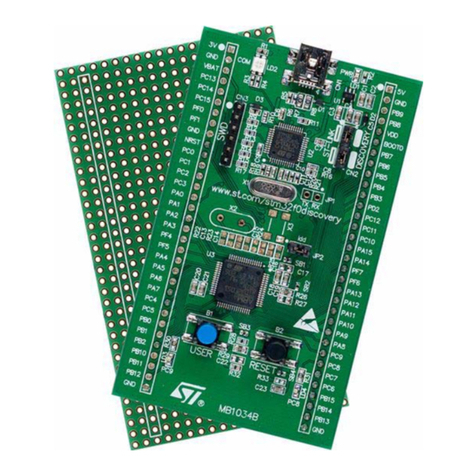
ST eMotion User manual

November 2006 Rev 1 1/29
UM0289
User manual
eMotion: a motion control kit based on ST10F276
Introduction
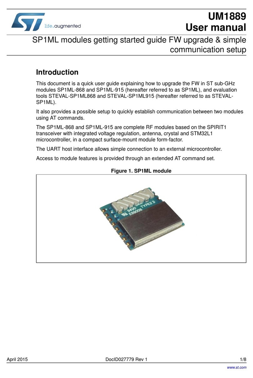
This user manual describes the features of the eMotion Kit, and explains how use the kit to
perform generic speed control of DC and BLDC motors.
Figure 1. eMotion kit
Key features
■GUI software (Windows XP OS-compatible)
■Control board MDK-ST10 (ST10F276 core, 16-bit DSP @ 64 MHz)
■Shielded interface board (for encoder feedback)
■powerSPIN boards (L6205 / L6235 eval)
■Configurable PID closed speed loop for up three motors DC or BLDC
■RS232 communication
www.st.com

Contents UM0289
2/29
Contents
1 Overview . . . . . . . . . . . . . . . . . . . . . . . . . . . . . . . . . . . . . . . . . . . . . . . . . . 3
1.1 Getting started . . . . . . . . . . . . . . . . . . . . . . . . . . . . . . . . . . . . . . . . . . . . . . 3
2 Hardware . . . . . . . . . . . . . . . . . . . . . . . . . . . . . . . . . . . . . . . . . . . . . . . . . . 5
2.1 MDK-ST10 . . . . . . . . . . . . . . . . . . . . . . . . . . . . . . . . . . . . . . . . . . . . . . . . . 5
2.2 PowerSPIN boards . . . . . . . . . . . . . . . . . . . . . . . . . . . . . . . . . . . . . . . . . . . 7
2.2.1 L6205 Eval board (DC Motor) . . . . . . . . . . . . . . . . . . . . . . . . . . . . . . . . . 7
2.2.2 L6235 Eval board (BLDC Motor) . . . . . . . . . . . . . . . . . . . . . . . . . . . . . . . 8
2.3 Feedback board . . . . . . . . . . . . . . . . . . . . . . . . . . . . . . . . . . . . . . . . . . . . . 9
3 PC software . . . . . . . . . . . . . . . . . . . . . . . . . . . . . . . . . . . . . . . . . . . . . . . 12
3.1 eMotion GUI . . . . . . . . . . . . . . . . . . . . . . . . . . . . . . . . . . . . . . . . . . . . . . . 12
3.1.1 EVAL 6235 window . . . . . . . . . . . . . . . . . . . . . . . . . . . . . . . . . . . . . . . . 12
3.1.2 EVAL 6205 window . . . . . . . . . . . . . . . . . . . . . . . . . . . . . . . . . . . . . . . . 14
3.1.3 Log window . . . . . . . . . . . . . . . . . . . . . . . . . . . . . . . . . . . . . . . . . . . . . . 16
4 ST10 firmware . . . . . . . . . . . . . . . . . . . . . . . . . . . . . . . . . . . . . . . . . . . . . 17
4.1 Communication protocol . . . . . . . . . . . . . . . . . . . . . . . . . . . . . . . . . . . . . . 17
4.2 Control algorithm . . . . . . . . . . . . . . . . . . . . . . . . . . . . . . . . . . . . . . . . . . . 21
5 Using eMotion . . . . . . . . . . . . . . . . . . . . . . . . . . . . . . . . . . . . . . . . . . . . . 23
5.1 Evaluate eMotion kit . . . . . . . . . . . . . . . . . . . . . . . . . . . . . . . . . . . . . . . . . 23
5.1.1 Installing eMotion GUI . . . . . . . . . . . . . . . . . . . . . . . . . . . . . . . . . . . . . . 23
5.1.2 Board configuration . . . . . . . . . . . . . . . . . . . . . . . . . . . . . . . . . . . . . . . . 23
5.1.3 Control operations . . . . . . . . . . . . . . . . . . . . . . . . . . . . . . . . . . . . . . . . . 24
6 Limitations . . . . . . . . . . . . . . . . . . . . . . . . . . . . . . . . . . . . . . . . . . . . . . . . 26
6.1 Hardware issues . . . . . . . . . . . . . . . . . . . . . . . . . . . . . . . . . . . . . . . . . . . . 26
7 Revision history . . . . . . . . . . . . . . . . . . . . . . . . . . . . . . . . . . . . . . . . . . . 27
Appendix A Bibliography . . . . . . . . . . . . . . . . . . . . . . . . . . . . . . . . . . . . . . . . . . . . 28

UM0289 Overview
3/29
1 Overview
1.1 Getting started
eMotion is a motion control kit able to manage up to 3 motors (DC or BLDC) simultaneously,
it can be used as starting point for the evaluation of control algorithms, motors and drivers.
The complete kit is composed of:
●Windows GUI (XP-compatible): a Multi-Windows software for managing, through a
serial connection, the control of up three motors.
●MDK-ST10 board: control board based on microcontroller ST10F276 and three
connectors compatible with a powerSPIN board (eval 62xx)
●Interface board: a board with two shielded connectors, to be stacked into the sockets of
MDK-ST10 to allow motor feedback of encoder signals.
●powerSPIN boards: the eMotion kit can manage up to three motor driver boards based
on L6205 (DMOS dual full bridge motor driver) and L6235 (DMOS fully integrated
three-phase motor driver) chips, for DC and BLDC motors respectively.
●Firmware for open/closed loop operation: a complete source library is developed to
manage the control of DC and BLDC motors in open loop mode (PWM and driver
settings) and closed loop mode (speed regulation with encoder feedback) using 62xx
eval boards.
●Protocol communication: a complete frame-based protocol is developed to allow the
exchange of data with GUI via standard RS232 channel.
Figure 2. eMotion kit block diagram
It is possible via the GUI to interact with the ST10F276 control board (MDK-ST10) and
generate open loop signals for up three DC or BLDC motors. The PWM frequency (17-30
kHz) and duty cycle (0-100%) can be managed together with driver signals such as
enable/disable, brake/unbrake (BLDC) and forward/reverse (DC).
The closed loop operation can be performed in terms of motor speed with encoder
feedback.
A complete PID (Proportional, Integrative, And Derivative) control algorithm is implemented.
The user can configure:
●the value of PID terms (from 0.01 to 100)
●the speed (from 1 to 3000 rpm)
●the control loop time (from 1 to 52 ms)
●the number of encoder pulses per revolution (1 to 65536)
PC + GUI
Board
Power
Control
board MDK
ST10
Feedback
board
(shielded)
PowerSPIN
boards
Encoder
signals Encoder
signals
Power
signals
PWM/
Driver
BLDC or
DC
motors
Driver
Power
RS232
Serial
Protocol

Overview UM0289
4/29
Encoder feedback signals are directly managed by the ST10F276 through its dedicated
peripherals.
In order to guarantee an optimum quality of encoder waveforms, a special adapter is
included to shield the signals and to avoid interference (refer to Section 2.3 on page 9 for
further information).

UM0289 Hardware
5/29
2 Hardware
2.1 MDK-ST10
(Refer to the MDK-ST10 User manual (UM0288) for more detailed information)
The core of the eMotion Kit is the control board which is based on the ST10F276
microcontroller, in which all the driver board management routines are implemented.
Board key features:
●ST10F276 core (16-bit with DSP @ 64 MHz, 832 KB Flash,68 KB RAM)
●RS232
●RS485
●2 CAN
●I2C (3.3V and 5V)
●MC Connector
●3 powerSPIN connectors
●VN808 board / GP connector
●All pin outs available
The board design allows the user to develop a high-end motion control system based on this
16-bit microcontroller. The features of this powerful device allow the integration of complex
routines to create advanced motion control algorithms.
Referring on Figure 2, the eMotion kit uses the connectors PowerSpin_1, 2, 3 as indicated
on the silkscreen of the board with the text "PractiSpin 1", "PractiSpin 2", "PractiSpin 3".
To allow the compatibility with powerSPIN evaluation boards, for each board connector is
inserted a jumper (VCC PRACTI X, located close to the connector) that, if closed, provides
a 5V power supply to the respective board.
Communication with a PC and GUI system is achieved via an RS232 channel through a
standard DB9 female connector and using a standard RS232 cable.

Hardware UM0289
6/29
Figure 3. MDK-ST10 board
Note: Refer also to Section 5.1.2: Board configuration on page 23
The default configuration of the board (once programmed) is:
●EA jumper: 1 (in order to obtain the fetch of the code from internal flash of
microcontroller)
●SW3 switches: all OFF
●
SW5 switches:
–Switch 2 (CSEL 0): ON
–Switch 7 (CLK 1): ON
–Other switches: OFF
●Selector J206: "PRACTI" position (in order to connect micro lines to powerSPIN
connectors)
These configurations impose a 60 MHz core clock frequency and leave port 6 of
microcontroller free for I/0s (needed because P6.0=CS0 is used to manage powerSPIN
boards)
To better understand how powerSPIN boards are managed by control board, Ta bl e 1
provides a description of the powerSPIN connectors:
MC_CONNECTOR
POWERSPIN_2
ST10F276
VN808 / GP
POWERSPIN_3
RS232
RS485
I2C
CAN2
CAN1
POWERSPIN_1

UM0289 Hardware
7/29
Table 1. PractiSPIN connectors description
2.2 PowerSPIN boards
eMotion kit can manage up to three boards based on monolithic driver of L62xx family. This
first release of system works with DC and BLDC drivers so with boards L6205 and L6235
but also with similar boards for the same motors.
2.2.1 L6205 Eval board (DC Motor)
(refer to application note AN1762 and the L620x datasheet for more details)
PIN No. PractiSPIN 1 PractiSPIN 2 PractiSPIN 3 Functionality
1
5V via Jumper
J207 (VCC
PRACTI 1)
5V via Jumper
J208 (VCC
PRACTI 2)
5V via Jumper
J209 (VCC
PRACTI 3)
-
2 P2_10 P2_11 P2_12 Interrupt
3 P5_5 P5_6 P5_7 ADC
4 P0L.0 P0L.1 P0L.2 GPIO
5, 6 NC NC NC -
7 P1L.0 P1L.1 P1L.2 ADC
8 P0L.3 P0L.4 P0L.5 GPIO
9NC NC NC -
10 P0L.6 P0L.7 P6.3 GPIO
11, 13 NC NC NC -
14 P6.0 P6.1 P6.2 GPIO
15, 16, 17, 18, 19 NC NC NC -
20 P2.0 P2.1 P2.2 GPIO / Capcom
21 NC NC NC -
22 P8.0 P8.1 P8.2 PWM / GPIO
23 GND GND GND -
24, 25 NC NC NC -
26 P7.4 P7.5 P7.6 GPIO / Capcom
27 NC NC NC -
28 P7.0 P7.1 P7.2 PWM / GPIO
29, 30 NC NC NC -
31 P2.13 P2.14 P2.15 GPIO / Capcom
32 P2.3 P2.4 P2.5 GPIO / Capcom
33 P1H.4 P1H.5 P1H.6 GPIO / Capcom
34 NC NC NC -

Hardware UM0289
8/29
eMotion kit can manage the evaluation board based on DMOS full bridge ICs
(L6205,L6206,L6207).
Figure 4. Eval 6205N board
Refer to Section 5.1.2: Board configuration on page 23 for a description of the board
configuration using eMotion.
2.2.2 L6235 Eval board (BLDC Motor)
(refer to application note AN1625 and the L6235 datasheet for more details)
eMotion kit can manage the evaluation board based on L6235 three phase brushless DC
motor.
Figure 5. Eval 6235 board
Refer to Section 5.1.2: Board configuration on page 23 for a description of the board
configuration using eMotion.

UM0289 Hardware
9/29
2.3 Feedback board
In order to interface the control system with encoder signals coming from motors, a special
board, with two 20 pins connectors in the top side, is used (Feedback board).
This is a stackable board and has to be inserted using the four 36-pin connectors around the
microcontroller in the MDK-ST10 board. The insertion orientation is indicated with a dot in a
corner of the board (corresponding to pin 1 of the ST10 MCU)
The two connectors (Conn1 J3, Conn2 J4), used to allow the encoder feedback, are
shielded with the pair of pins connected to GND.
The dimensions of this board are about 6.5 x 6.5 cm. The following tables show the pin
assignments for each connector.
Table 2. Conn1 Feedback board
Table 3. Conn2 Feedback board
Conn.1 MDK-ST10 Pin Functionality
1 P3.7 T2IN (encoder_1 A)
2GND-
3 P5.15 T2EUD (encoder_1 B)
4GND-
5 P3.6 T3IN (encoder_2 A)
6GND-
7 P3.4 T3EUD (encoder_2 B)
8GND-
9 P3.5 T4IN (encoder_3 A)
10 GND -
11 P5.14 T4EUD (encoder_3 B)
12 GND -
13 P2.6 CC16 (capture / GPIO)
14 GND -
15 P1L.3 GPIO / ADC In
16 GND -
17 P1L.4 GPIO / ADC In
18 GND -
19 +5V -
20 GND -
Conn.2 MDK-ST10 Pin Functionality
1 P1L.5 GPIO/ ADC In
2GND-
3 P2.7 CC7 (capture / GPIO)

Hardware UM0289
10/29
Figure 6. Feedback board schematic
4GND-
5 P1L.6 GPIO / ADC In
6GND-
7 P1L.7 GPIO / ADC In
8GND-
9 P1H.0 GPIO
10 GND -
11 P1H.7 CC27 (capture / GPIO)
12 GND -
13 P1H.1 GPIO
14 GND -
15 P1H.2 GPIO
16 GND -
17 P1H.3 GPIO
18 GND -
19 +5V -
20 GND -
Conn.2 MDK-ST10 Pin Functionality

UM0289 Hardware
11/29
Figure 7. Feedback board - TOP
In order to report the feedback of motors, a 20-pin flat cable could be used. The first
connector can be used for an incremental encoder as the timer pins are used for
incremental interface mode. The second connector can be used for absolute encoder
feedback where the GPIO and capture pins are used.
Note: The system allows the feedback of encoder signals (A and B channels) for each motor,
Signals must be squared and with the right logic level (0 and 5V). When necessary, refer to
the datasheet of the encoder used. If needed, pull-up the encoder signals (not provided with
encoder kit).

PC software UM0289
12/29
3 PC software
The parameters of eMotion system can be configured through a Windows-based GUI
(eMotion GUI), that interacts with the control board via an RS232 straight cable.
The following paragraphs provide a description of all the software features.
3.1 eMotion GUI
Refer to Section 5.1.1: Installing eMotion GUI on page 23 for the installation procedure.
After start-up of the eMotion GUI, a series of menu functions are available to the user:
File:
Connect: Open the "Serial Port Selection" window, from which it is possible to select the
serial port to open the communication between the PC and the MDK-ST10 board
Disconnect: Close the connection between the PC and the MDK-ST10 board.
New: Open a new 6205 or 6235 window (for a DC or BLDC motor respectively)
Log Window: Open the Log Window. In this window it is possible to see the communication
data as a hexadecimal value sent to the MDK-ST10 board
Exit: Exit the program
View:
To o l b a r : Display or hide the toolbar
Status Bar: Display or hide the status bar in the bottom-right corner of the main window
Help
Help Topics: Open the Help Topics
About: Displays eMotion Project credits
3.1.1 EVAL 6235 window
The 6235 window allows the user to drive a BLDC motor through the EVAL6235 board. After
starting eMotion, click on the 6235 window icon or choose New - 6235 window from the
File menu. A new 6235 window opens.

UM0289 PC software
13/29
Figure 8. 6235 window
The Connector Selection panel shows the connector of the MDK-ST10 with which the
EVAL6235 can be connected (some connector selections could be disabled if the connector
is used by other windows). The left part of this window allows the user to control a BLDC
motor in open loop mode. The right part of the window allows the user to perform a PID
speed closed loop control with encoder feedback.
The Motor Control Command panel is always enabled, while the Control Parameters and
Control Loop Time panels are disabled when the Closed Loop check button is not checked.
In each case the Get button is always enabled.
Motor Control Command panel:
●Enable: Enables the 6235 driver. This command switches ON all Power MOSFETs of
the driver (pin EN high).
●Disable: Disables the 6235 driver. This command switches OFF all Power MOSFETs of
the driver (pin EN low).
●Unbrake: Sets the pin BRAKE high of the 6235 and enables the normal mode (six step
control strategy).
●Brake: Sets the pin BRAKE low of the 6235. This command switches ON all High Side
Power MOSFETs, implementing the Brake Function.
●Duty Cycle Set: This slider allows the user to set the duty cycle of the PWM generated
by the ST10 as input for the FWD/REV pin of the 6235 driver. Values between 0 and
50% cause the rotation of the motor in one direction, while values between 50% and
100% cause the rotation of the motor in the other direction. A 50% value corresponds
to no motor rotation.
Note: The real direction (clockwise or counterclockwise) depends on the connection between the
6235 and the motor.
●PWM set: This slider allows the user to change the frequency of the PWM generated by
the ST10. The allowed values go from a minimum of 17 kHz to a maximum of 30 kHz.
(with 1 kHz steps)
Note: At system startup the default values are: disable, brake, PWM duty cycle 50%, PWM
frequency 17 kHz.

PC software UM0289
14/29
Enable/Disable Control Parameters panel:
●Closed Loop: This check control enables/disables the text boxes and push buttons of
the Control Parameters and Control Loop Time panels.
Control Parameters panel:
This panel allows the user to perform a PID speed closed loop control with encoder
feedback. The user must fill the following text boxes and then press the Set button in order
to set the control parameters:
●Enc. Pulses/r: The number of pulses per revolution of motor encoder.
●Speed: Speed of the motor expressed in RPM. Allowed values go from 0 to 3000 rpm
(steps 1 rpm).
●P: Proportional gain of the PID control. Allowed values go from 0 to 100, in steps of
0.01.
●I: Integral gain of the PID control. Allowed values go from 0 to 100, in steps of 0.01.
●D: Derivative gain of the PID control. Allowed values go from 0 to 100, in steps of 0.01.
●Set: Set the control parameters.
Note: If values out of range are inserted in one or more text boxes, a pop-up window will appear
indicating that at least one value is out of range.
●Start: Start the PID speed closed loop control. The rotation of the motor remains the
same of the motor before starting the control.
●Stop: Stop the PID speed closed loop control. The motor will rotate with a speed
accordingly to the duty cycle calculated in the last control routine before stopping.
●Get: This command returns the status of the control parameters and of the control loop
time actually memorized in the MDK-ST10 board.
Control loop time:
This text box allow the user to insert the value of control loop time (in case of closed loop
operation); the range of this parameter is from 1 to 52 ms (with 200 us steps)
Note: For control loop time is intended the frequency of adjustment of PWM duty cycle (according
to PID action) in order to reach the speed reference.
3.1.2 EVAL 6205 window
The 6205 window is designed to allow the user to drive a DC motor through EVAL6205.
After starting eMotion click on the 6205 window icon or choose New - 6205 window from the
File menu. A new 6205 window is now opened.
Note: The functions of this window are the same of 6235 window, except for the motor control
panel.

UM0289 PC software
15/29
Figure 9. 6205 window
The Connector Selection panel shows the connector of the MDK-ST10 with which the
EVAL6205 can be connected (some connector selections could be disabled if the connector
is used by other windows). The left part of this window allows the user to control a DC motor
in open loop mode. The right part of the window allows the user to perform a PID speed
closed loop control with encoder feedback.
The Motor Control Command panel is always enabled, while the Control Parameters and
Control Loop Time panels are disabled when the Closed Loop check button is not checked.
In each case the Get push button is always enabled.
Motor Control Command panel:
●Enable: Enables the 6205 driver. This command switches ON all Power MOSFETs of
the driver (pin EN high).
●Disable: Disables the 6205 driver. This command switches OFF all Power MOSFETs of
the driver (pin EN low).
●Forward: This command set low the pin IN1 of the EVAL6205 (pin IN1A of 6205 driver).
●Reverse: This command set high the pin IN1 of the EVAL6205 (pin IN1A of 6205
driver).
●Duty Cycle Set: This slider allows the user to set the duty cycle of the PWM generated
by the ST10 as input for the IN2 of the EVAL6205 (pin IN2A of the 6205 driver).The
direction of rotation of the motor depends on the Forward/Reverse radio buttons. If
Forward (Reverse) radio button is checked a value of PWM of 0% (100%) stops the
motor while a value of PWM of 100% (0%) runs the motor at maximum velocity.
Note: The real direction (clockwise or counterclockwise) depends on the connection between the
6205 and the motor.
●PWM set: This slider allows the user to change the frequency of the PWM generated by
the ST10. The allowed values go from a minimum of 17 kHz to a maximum of 30 kHz
(steps 1 kHz).
Note: At systems startup the default value are: disable, forward, PWM duty cycle 50%, PWM
frequency 17 kHz.
Enable/Disable Control Parameters panel:
Refer to Section 3.1.1: EVAL 6235 window on page 12.

PC software UM0289
16/29
Control Parameters panel:
Refer to Section 3.1.1: EVAL 6235 window on page 12.
Control loop time:
Refer to Section 3.1.1: EVAL 6235 window on page 12.
3.1.3 Log window
Using the log window is possible to view the frames sent and received by the GUI (to check
the state of communication with the board).
A text string is shown explaining the command and also the hexadecimal value of the
command (refer to Section 4.1: Communication protocol on page 17).
Figure 10. Log window

UM0289 ST10 firmware
17/29
4 ST10 firmware
The firmware to manage the eMotion system is organized in two separate modules:
●Communication module: able to exchange data with the PC-GUI using a structured
protocol.
●Control module: able to perform the open and closed loop operation on three motors
and communicates with the first module.
Note: All the firmware is developed, in standard C language, using tasking toolchain v 8.5 from
Altium.
4.1 Communication protocol
The serial protocol used for communicate with PC-GUI is a frame based protocol, with a
baud rate of 115200, 8-bit data length, no parity check, 1 bit stop.
The frame has a variable length, with a CRC field. A mechanism of acknowledgement for
each command is implemented.
Figure 11. Frame protocol
Figure 11 shows the general frame format on which the communication is based, the CRC is
a field of 1 byte length computed with this formula:
16_Total_Length = (16_bit) (FRAME_TYPE + LENGTH + DATA)
CRC = (8_bit) (High_Byte(16_Total_Length) + Low_Byte(16_Total_Length))
Tabl e 4 shows the general description of the frames.
Table 4. Frame description
Frame name Description Frame Type Length Direction Type
Connect Open
connection 0x00 0 PC-MDK ST10 Command
Enable_Motor Enable motor
drive 0x01 1 PC-MDK ST10 Command
Disable_Motor Disable motor
drive 0x02 1 PC-MDK ST10 Command
Brake_Motor Enable brake
motor drive 0x03 1 PC-MDK ST10 Command
Unbrake_Motor Disable brake
motor drive 0x04 1 PC-MDK ST10 Command
Forward_Motor
Set forward
motor direction
(6205 motor
drive)
0x05 1 PC-MDK ST10 Command
Frame Type Length Payload CRC
1 byte 1 byte variable length 1 byte

ST10 firmware UM0289
18/29
The length field indicated the number of bytes in the payload.
In each frame (with length greater than 0) the first byte of the payload indicates the
association connector-powerspin board (except "Send_Latest_Error") (see Ta bl e 5 ):
Table 5. Connector-Eval62xx
Reverse_Motor
Set reverse
motor direction
(6205 motor
drive)
0x06 1 PC-MDK ST10 Command
Set_PWM Set duty cycle
of PWM 0x07 2 PC-MDK ST10 Command+Data
Set_Freq_PWM Set frequency
of PWM 0x08 2 PC-MDK ST10 Command+Data
Set_PID_Contr
ol
Set the PID
and speed
values
0x09 12 PC-MDK ST10 Command+Data
Set_Control
_Loop Time
Set the time for
executing the
closed control
loop
0x0A 2 PC-MDK ST10 Command+Data
Get_Parameter
s
Get the control
parameters. 0x0B 1 PC-MDK ST10 Command
Start_Control Start control
loop 0x0C 1 PC-MDK ST10 Command
Stop_Control Stop control
loop 0x0D 1 PC-MDK ST10 Command
Get_Latest_Err
or
Get Latest
error occurred 0x0E 0 PC-MDK ST10 Command
Send_Paramet
ers
Transmission
of the
parameters
values
0x40 15 MDK ST10-PC Data
Send_Latest_E
rror
Send latest
error occurred 0x41 1-50 MDK ST10-PC Data
ACK
Confirm the
correct
reception of a
frame
0x80 1 MDK ST10-PC
PC-MDK ST10 Acknowledgment
Byte Value
0x1A First connector with eval 6235
0x1B First connector with eval 6205
0x2A Second connector with eval 6235
0x2B Second connector with eval 6205
Frame name Description Frame Type Length Direction Type

UM0289 ST10 firmware
19/29
ACK timeout is fixed at 10 ms, both for the PC and ST10, and the payload of the "ACK"
frame is the command code to be acknowledged.
"Set_PID_Control" (0x09) is the frame used for setting the specific values of each control
loop, the contents of this frame is shown in the table below.
Table 6. Table 6 - Set_PID_Control payload
"Set_Control_Loop time" (0x0A) is a frame used to set the control loop time of each motor
control, according to the table below.
Table 7. Set_Control loop time payload
"Send_Parameters" (0x40) is a particular frame used to send the status of all system
parameters to the PC, the contents of this frame is shown in Ta b l e 8 .
0x3A Third connector with eval 6235
0x3B Third connector with eval 6205
Payload
byte order Field Description
1 Motor Connector Association connector-powerSPIN board
2Driver Byte for reserved use, indicating the kind of driver
(0xCD for a6205,0xEB for a 6235)
3-4 Encoder 2 Bytes indicating number of pulse for revolution of
motor encoder.
5-6 Speed 2 Bytes indicating the reference speed of motor
(range 1-3000 rpm)
7-8 P
2 Bytes indicating the proportional gain of the
speed control (range 1-1000, with a firmware
scaling)
9-10 I 2 Bytes indicating the integral gain of the speed
control (range 1-1000, with a firmware scaling)
11-12 D 2 Bytes indicating the derivative gain of the speed
control (range 1-1000, with a firmware scaling)
Payload
byte order Field Description
1 Motor Connector 1 Byte indicating which powerSPIN board is connected
to a specific connector.
2Time Byte indicating the control loop time (number of 200us
steps to be added to the basic control loop of 1ms).
Byte Value

ST10 firmware UM0289
20/29
Table 8. Send_Parameters contents
"Send latest error" (0x41) is a particular frame in which the payload is formed by a text string
indicating the last error occurred, typical values are shown below.
Table 9. Error strings
A series of protocol frames, used for communication, are provided in Ta bl e 1 0 .
Table 10. Frame examples
Payload
byte order Field Description
1 Motor Connector 1 Byte indicating which powerSPIN board is connected to
a specific connector.
2-3 Encoder 2 Bytes indicating the number of pulses for revolution of
motor encoder.
4PWM% Byte indicating the duty cycle value of PWM (range: 0-
100)
5 PWM Freq. Byte indicating the frequency PWM (range: 17-30)
6 Time control loop Byte indicating the control loop time (number of 200us
steps to be added to the basic control loop of 1ms).
7 Status Byte indicating if the control is enabled (0 or 1)
8-9 Speed 2 Bytes indicating the reference speed of motor (range 1-
3000 rpm)
10-11 P 2 Bytes indicating the proportional gain of the speed
control (range 1-1000, with a firmware scaling)
12-13 I 2 Bytes indicating the integral gain of the speed control
(range 1-1000, with a firmware scaling)
14-15 D 2 Bytes indicating the derivative gain of the speed control
(range 1-1000, with a firmware scaling)
String Types
No error
CRC not valid
Command not valid
Command not executable
Motor error
Value out of range
Frame Description Value (Hex)
Connect 00-00-00
Enable 6235 driver on powerSPIN connector 1 01-01-1A-1C
Brake 6205 driver on powerSPIN connector 3 03-01-3B-3F
ACK for a Forward command 80-01-05-86
Table of contents
Other ST Control Unit manuals
Popular Control Unit manuals by other brands

AVK
AVK 816 Series Maintenance and Instruction Manual

Allen-Bradley
Allen-Bradley 1492-IFM40F-3 manual

Dungs
Dungs GasMultiBloc MBC-65 Series instructions

Allen-Bradley
Allen-Bradley 1771-QDC manual

Belden
Belden GRASS VALLEY MDX-3901 Guide to installation and operation

CLA-VAL
CLA-VAL 43-01/643-01 Installation, operation and maintenance manual