IDEC LUMIFA LF3D User manual

LED Lighting
LF3D/LF1D
Excellent optical performance and robust construction
suitable for use in machine tools
TM

2
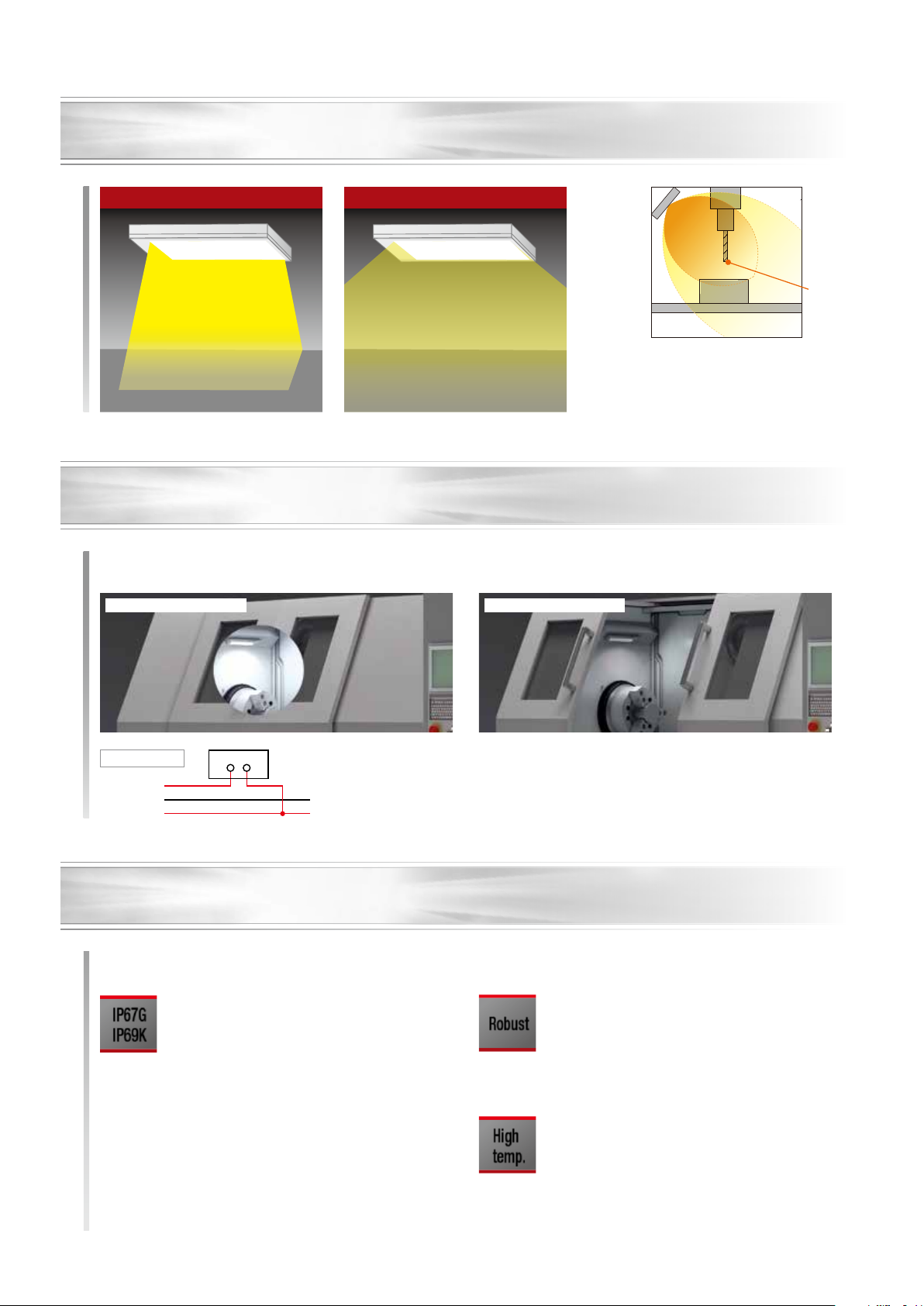
LED lighting inside machine tool allows for clear identification of chatter marks
▲
LED lighting improves machining efciency
IDEC's unique optical technology enables the light to shine evenly on
the surface, suppressing multiple shadows and allowing the operator to
see scratches and unevenness on the workpiece. LF3D lighting makes
it possible to check whether chatter marks have been generated or not
easily, at a glance.
▲
Hard to see chatter marks
Glares from LED lighting inside the machine tool could be mistaken
as chatter marks while visually checking the machine operation. This
often caused chatter marks to be left untreated, delaying maintenance
and worsening the situation.
AFTER
BEFORE
Effective solution for machine tools

3
Eliminates the
multi-shadow effect
▲
Reduced multi-shadow effect enables easy visual inspection of the
machined surface. [Patent pending (LF3D)]
Reduces reflection
from light source
Surface reflection
Surface reflection
LF3D
Conventional Product
LED light source reflects
on the workpiece and
stripes appear.
By combining our optical design
technology gained by
development of LED lighting &
sensors and by optimum LED
alignment, the brightness
contrast difference is improved
by 85%.
The LF3D LED allows the
light to be evenly distrib-
uted to provide natural
lighting, and enables
visual inspection.
[Patent pending (LF3D)]
Conventional Product LF3D
LED
Brightness
contrast
difference
Bright Dark Bright Dark
Brightness
distribution
of illumina-
tion surface
Difference
Difference
Uniform lighting
provides uniform
illumination inside
the work area
LF3D
Conventional Product
LF3D-S (surface mount)
LF3D-F (recessed mount)
4
Suitable for use in machine tools
Degree of protection IP67G / IP69K
Robust material
Resistant to high temperature
Oil-resistant gasket and unique structural design achieves
IP67G protection degree. (*1)
Withstands exposure to water and oil. (*2)
IP69K for use in high-pressure, high-temperature washdown.
*1) IP67F (LF1D)
*2) Oil used for testing: Insoluble oil JIS N3-8
Reinforced glass, stainless steel, zinc diecast, extruded
aluminum prevents damage from scraps
Wide operating temperature range (up to 55C).
Robust
High
temp.
IP67G
IP69K
Dim light (*1) (door: closed)
100% illumination (door: closed)
Application example: Functions with opening & closing of doors / switching with control panel
*At least 500 lx shall be provided when arranging lighting for
machines.
(EN1837:1999+A1:2009 4.2)
LED lighting
500lx min.
Standard distribution Diffused distribution
Switch, etc.
–(0V)
+(24V DC)
White (pin No.2)
Blue (pin No.3)
Brown (pin No.1)
Modes can be changed by just the wiring. Complicated settings such as PWM and dedicated controllers are not required.
[Patent pending (LF3D)]
*1) Approx. 40% illumination
Equipped with glare mode to prevent operators from glare during maintenance
Select from standard or diffused light distribution depending on the machine tool needs
Wiring diagram
Rugged construction and environmentally resistant
5
Wide selection of models to suit a various machine tools
For small to medium machines For large machines
Application Standard lens provides brilliant light on the edges of tools and work pieces.
Diffused lens provides wide light distribution inside work areas.
Wide illumination inside the work
area or replacements for
uorescent lamps
Part no. LF3D-S LF3D-F LF1D-H/J
Shape Surface mount Recessed mount Surface mount
Luminous Flux
(typ.) 1700 lm 2000 lm (LF1D-H)
3000 lm (LF1D-J)
Reference
Illuminance (typ.)
at 1.0m directly
below
1800 lx (standard distribution)
1000 lx (diffused distribution)
560 lx (LF1D-H)
840 lx (LF1D-J)
Dimensions
(W × H × D) 55.8 × 17.5 × 310 mm 80 × 27 × 307 mm
84 × 24.8 × 365 mm
(LF1D-H)
84 × 24.8 × 510 mm
(LF1D-J)
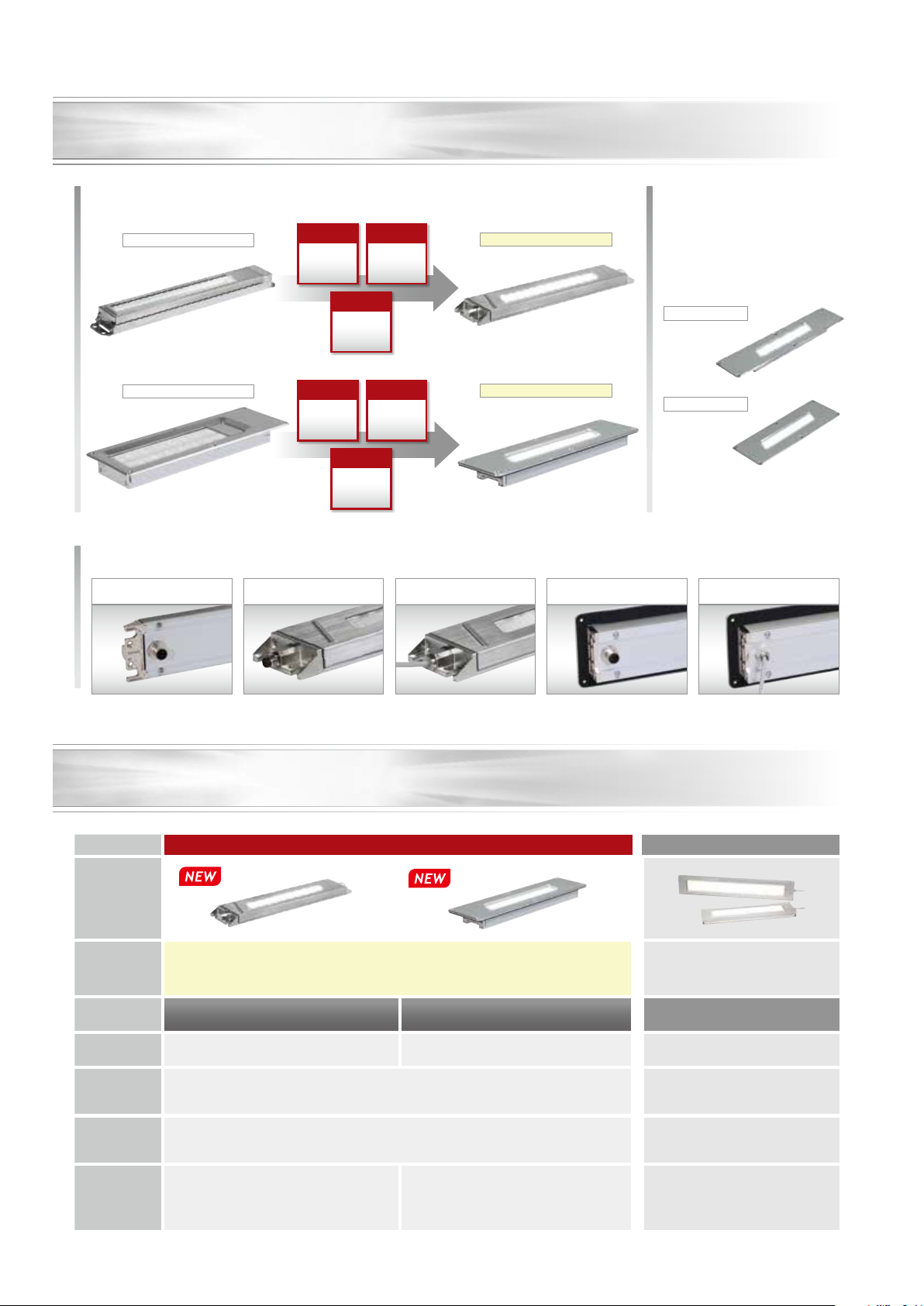
Compact, slim, and light compared to conventional products
Weight
30%
DOWN
Weight
25%
DOWN
Luminous
efciency
37%
UP
Mass
50%
DOWN
Wide variety of connector types available
Easy replacement
with conventional
products
Panel cut-out for older LED lighting
will t the new LF3D LED.
Accessories for surface mount type
replacements available.
Surface mount/Side cable
(LF3D-SB2S05M)
Recessed mount/Back M12
(LF3D-FB1B1)
LF3D-S (surface mount)
LF3D-F (recessed mount)
Luminous
efciency
47%
UP
Mass
40%
DOWN
Surface mount/Side M8
(LF3D-SB2S2)
LF2D-E
LF2D-F
Surface mount/Back M12
(LF3D-SB1B1)
Recessed mount/Back cable
(LF3D-FB1B05M)
Improved design and user-friendly
LF1D-EN (surface mount)
LF2D-FH (recessed mount)

LF3D/LF1D LED Lighting
6
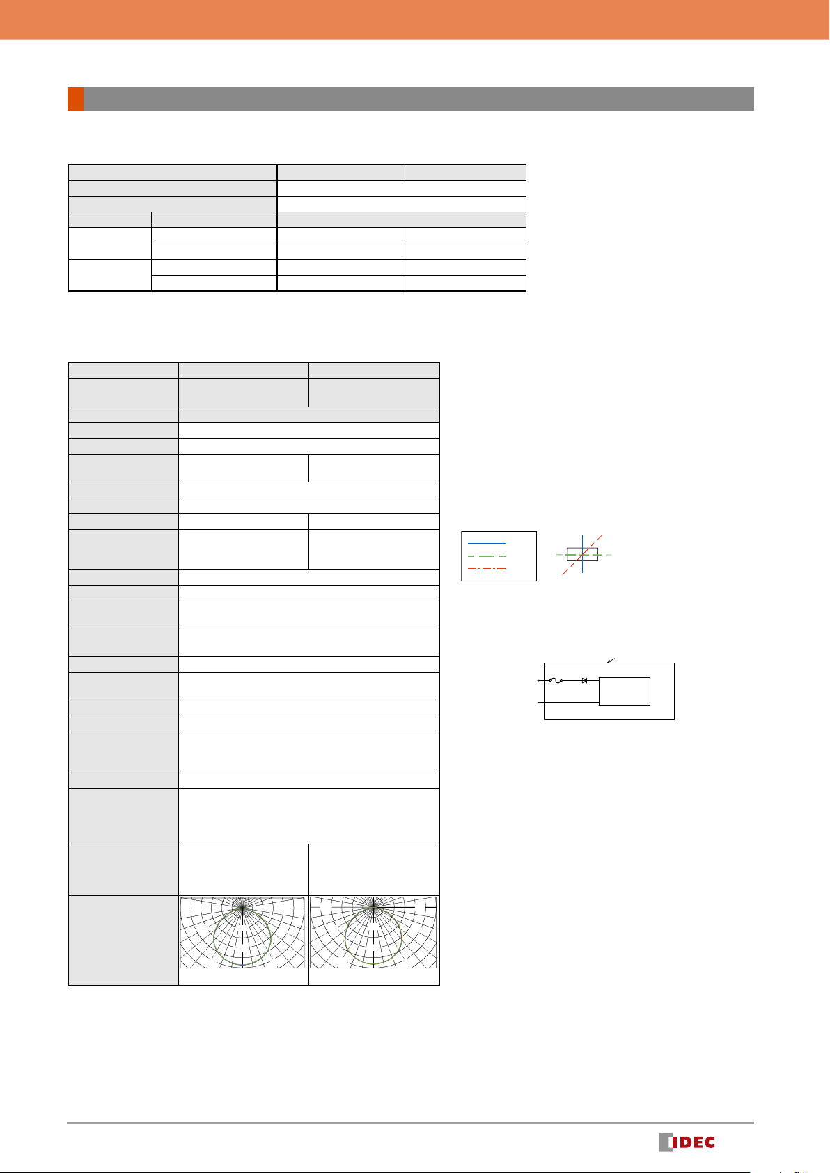
Internal Circuit
LF3D Package Quantity: 1
Model LF3D
Light distribution Standard Diffused
Style Surface mount (*1) Recessed mount Surface mount (*1) Recessed mount
Illumination surface Reinforced glass
Connection
direction
Cable /
Connector Part no. (Ordering no.)
Side 5m cable LF3D-SB2S05M —LF3D-SB1S05M —
M8 connector LF3D-SB2S2 LF3D-SB1S2
Rear
5m cable —
LF3D-FB2B05M
—
LF3D-FB1B05M
LF3D-F1B2B05M (*2)LF3D-F1B1B05M (*2)
LF3D-F2B2B05M (*3)LF3D-F2B1B05M (*3)
M12 connector LF3D-SB2B1
LF3D-FB2B1
LF3D-SB1B1 LF3D-FB1B1
LF3D-F1B2B1 (*2)
LF3D-F2B2B1 (*3)
*1) Contact IDEC for customers using LF1D–E (EH/EN) or LF1D–F (FH).
*2) Size and mounting centers compatible with LF2D–E (EH/EN). (LF3D-F1)
*3) Size and mounting centers compatible with LF2D–F (FH). (LF3D-F2)
Performance Specifications
Model LF3D
Style Uniform light source / slim type
Light distribution Standard Diffused
Rated voltage 24V DC
Operating voltage range 21.6 to 26.4V DC
Rated Power (typ.)
(at rated voltage) 9.2W
Illumination color Cool white
Color temp. (typ.) 5700K
Luminous Flux (typ.) 1700 lm
Reference Illuminance (typ.)
at 1.0m directly below 1800 lx 1000 lx
Insulation resistance 100M minimum (500V DC megger)
Dielectric strength 1000V AC, 50/60Hz, 1 minute
Vibration resistance
(damage limits) Frequency 5 to 55Hz, amplitude 0.5mm
Shock resistance
(damage limits) 1000m/s2
Operating temperature –30 to +55°C (no freezing)
Operating relative humidity 45 to 85%RH (no condensation)
Storage temperature –35 to +70°C (no freezing)
Operating atmosphere No corrosive gas
Light source life (*1)
50,000 hours (The illumination duration in which the brightness
maintains a minimum of 70%)
(Ta = 25ºC, 45%RH max.)
Degree of protection (*2) Surface mount: IP65, IP67, IP67G, IP69K
Recessed mount: IP65, IP67, IP67G
Glare save mode
(GS-Mode) (*3)
White wire (pin no.1) - open: 100% light on
White wire (pin no.1) and brown wire (pin no. 2) - short-circuit: dim light
Material (Main parts)
Main body: Aluminum
Front cover (surface mount): Stainless steel
Flange (recessed mount): Aluminum
Side cover: Zinc die-cast (plating)
Illumination part surface: Reinforced glass
Gasket: NBR
Weight (approx.) LF3D-S: 680g (*4)
LF3D-F: 770g (*4)
LF3D-F1: 830g (*4)
LF3D-F2: 870g (*4)
Light Distribution Curve
(reference value)
(unit: cd/1000 lm)
200
400
600
800
1000
1200
90°90°
30°
60°60°
0°
30°
90°90°
30°
60°60°
0°
30°
100
200
300
400
500
600
A
C
B
A
B
C
A-A
B-B
C-C
Cross-sectional direction of light distribution
Blue (pin no. 3)
Brown (pin no. 1)
Brown (pin no. 1)
White (pin no. 2)
(–)
(+)
定電流形電源
+ LED
筐体
Housing
Constant-current
power supply
+ LED
Housing
Constant-current
power supply
+ LED
Blue (pin no. 3)
(LF3D only)
LF3D LED Lighting
• Due to variations in LED elements, products may vary in illumina-
tion color and illuminance.
*1) Not a guaranteed value. The actual life may differ depending on
the operating environment and conditions. Specications are
subject to change without notice.
Ta is the ambient temperature of this product.
*2) Testing conditions specied by IEC60529 (IP67), JIS C 0920
(IP67F/IP67G), and DIN40050-9 (IP69K)
Not guaranteed for every operating condition (the rated value of
the protective structure is when the product is mounted.)
*3) Dimming differs according to the operating environment.
Not a xed value. (Ta=25ºC typ.)
*4) Weight of cable type.
7
LF3D/LF1D LED Lighting
LF1D
LF1D-H/LF1D-J Long type Package Quantity:
Model LF1D-H LF1D-J
Mount style Surface mount
Illumination surface Reinforced glass
Cable direction Cable length Part no. (Ordering no.)
Side 5m LF1D-H2F-2N-350 LF1D-J2F-2N-350
1.5m + M12 connector LF1D-H2F-2N-3B0 LF1D-J2F-2N-3B0
Rear 5m LF1D-H2F-2N-450 LF1D-J2F-2N-450
1.5m + M12 connector LF1D-H2F-2N-4B0 LF1D-J2F-2N-4B0
Performance Specifications
Model LF1D-H LF1D-J
Style Long type
L=365mm
Long type
L=510mm
Light distribution Diffused
Rated voltage 24V DC
Operating voltage range 21.6 to 26.4V DC
Rated Power (typ.)
(at rated voltage) 18.4W 27.6W
Illumination color Neutral white
Color temp. (typ.) 4700K
Luminous Flux (typ.) 2000 lm 3000 lm
Reference Illuminance
(typ.)
at 1.0m directly below
560 lx 840 lx
Insulation resistance 100M minimum (500V DC megger)
Dielectric strength 1000V AC, 50/60Hz, 1 minute
Vibration resistance
(damage limits) Frequency 5 to 55Hz, amplitude 0.5mm
Shock resistance
(damage limits) 1000m/s2
Operating temperature –30 to +55°C (no freezing)
Operating relative
humidity 45 to 85%RH (no condensation)
Storage temperature –35 to +70°C (no freezing)
Operating atmosphere No corrosive gas
Light source life (*1)
50,000 hours (The illumination duration in which the
brightness maintains a minimum of 70%)
(Ta=25ºC, 45%RH max.)
Degree of protection (*2) IP67, IP67F, IP69K
Material (Main parts)
Main body: Aluminum
Front cover (surface mount): Stainless steel
Illumination part surface: Reinforced glass
Gasket: NBR
Weight (approx.) LF1D-H2F-2N-350: 1200g LF1D-J2F-2N-350: 1600g
Light Distribution Curve
(reference value)
(unit: cd/1000 lm)
90
°
90
°
60
°
0°
30
°
60
°
100
30 °
200
90
°
90 °
60 °
0°
30
°
60
°
100
30 °
200
Internal Circuit
Blue (pin no. 3)
Brown (pin no. 1)
Brown (pin no. 1)
White (pin no. 2)
(–)
(+)
定電流形電源
+ LED
筐体
Housing
Constant-current
power supply
+ LED
Housing
Constant-current
power supply
+ LED
Blue (pin no. 3)
A
C
B
A
B
C
A-A
B-B
C-C
Cross-sectional direction of light distribution
LF1D LED Lighting
• Due to variations in LED elements, products may vary in illumination
color and illuminance.
*1) Not a guaranteed value. The actual life may differ depending on the
operating environment and conditions. Specications are subject to
change without notice.
Ta is the ambient temperature of this product.
*2) Testing conditions specied by IEC60529 (IP67), JIS C 0920 (IP67F/
IP67G), and DIN40050-9 (IP69K)
Not guaranteed for every operating condition (the rated value of the
protective structure is when the product is mounted.)

8
LF3D/LF1D LED Lighting
Connector Wiring
M12 connector type (A coding)
Pin no. Wiring color Function Connection
➀Brown +DC Power Supply +24V
➁White GS Mode Open or +DC
➂Blue -DC Power Supply 0V(GND)
➃– N.C.
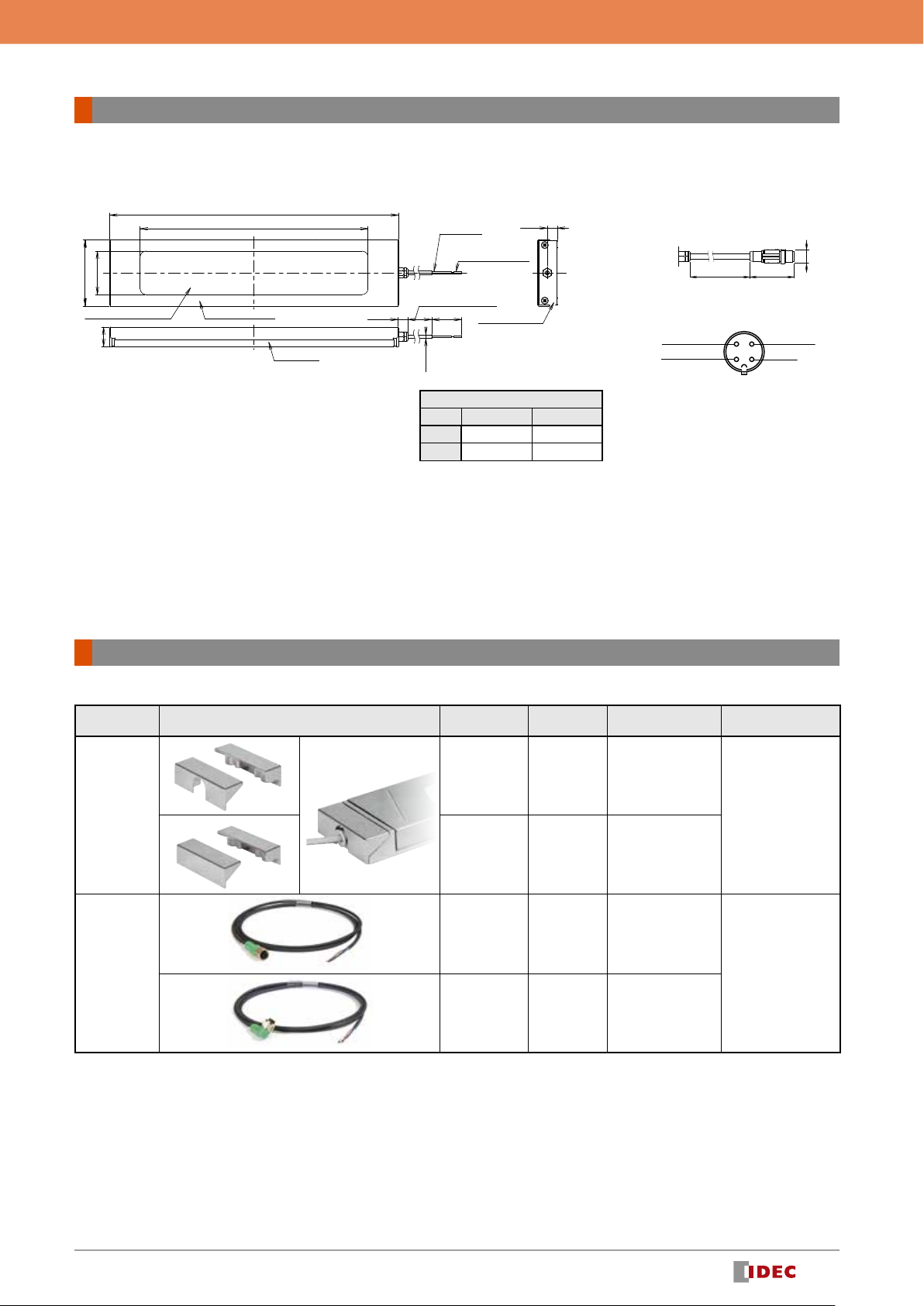
Dimensions (mm)
Model LF3D-F LF3D-F1 LF3D-F2
A 307 389 308
B 292 374 293
C 80 80 105
D 65 65 90
E 292 374 293
F 284 366 286
G 65 65 90
H 55 55 80
Use a connector on a power
supply side that satisfies the
required degree of protection.
Phoenix Contact (M12 con-
nector)
Mounting hole layout
Illumination
surface
Main body
Side cover
Flange
6-M5×10 Hexagon socket
+ Gasket (supplied with LF3D)
Cable length: 5m
6-M5 screw hole
or tapped hole
184.8
D
C
31
A
B
3
27
124.5
F
E
H
G
ø4
①
④
②
③
5m cable type
(33)
(34.5)
M12 connector type
Connector Wiring
LF3D (surface mount)
M8 connector
Pin No. Wiring color Function Connection
➀Brown +DC Power Supply +24V
➁White GS Mode Open or +DC
➂Blue -DC Power Supply 0V(GND)
➃– N.C.
Use a connector on a power supply side that satisfies the
required degree of protection.
Recommended connector: Harting (M8 connector)
Phoenix Contact (M12 connector)
Illumination
surface
Front cover
Side cover
Body
*1) When M12 connector is used
*1) When M12 connector is used
Mounting hole layout (M5 screw)
Mounting hole layout (M6 screw)
When LF9Z-B2 is used
Cable length: 5m
4-M4
26
4-M5 screw hole
or tapped hole
4-M6 screw hole
or tapped hole
310
184.8
55.8
17. 5
ø4
40±0.2
38±0.2
292 ±1.0
296 ±1.0
315.2
305
124.5
124.5
40
ø20 (*1)
ø20 (*1)
P0.7
④
③
②
①
①
④
②
③
5m cable
17. 5
M8 connector
17. 5
(30.5)
M12 connector
M12 connector
(A coding)
LF3D (recessed mount)
Dimensions (LF3D)
Dimensions in mm
9
LF3D/LF1D LED Lighting
Item Shape Type Part no.
(Ordering no.) Package quantity Remarks
Mounting
Bracket
Example(LF9Z-B21)
Side connection LF9Z-B21
2
(for right and left,
supplied with mounting
screws)
Bracket used for
mounting LF1D-E (EN/
EH) from the back with
the same mounting
centers.
Back connection LF9Z-B22
2
(for right and left,
supplied with mounting
screws)
M12 connector
cable
Straight LF9Z-CM13 1
Length: 3m
Right angle LF9Z-CM23 1
• Accessories are not supplied with the product.
Accessories exclusive for LF3D
Note: For mounting hole layout and the size of mounting screws on the back of the LED unit, see the specication sheet and dimensions supplied with the product.
Connector Wiring
LF1D-H/J2F-2*-*B*
(M12 connector)
(+)
(–) (+)
(–)
1470 46.8
ø14.8
➀+24V DC
➂-0V DC
➃NC
➁NC
Plug 4-pin assignment
M12 connector: SAC-4P-MS SCO/150/1.5
Use a connector on the power sup-
ply side that satises the degree of
protection.
Recommended connector:
Phoenix Contact
SAC-4P-1.5-PUR/FS SCO
LF1D-H [long type] L=365mm] / LF1D-J [long type L=510mm]
Dimensions (mm)
Model LF1D-H LF1D-J
A 365 510
B 288 432
A
55
B
84
24.8
ø4.6
12.5 (35)
Cable length 5 m
12.7
Side cover
Semi-stripped × (2)
24AWG
Front cover
Illumination surface
Main body
Brown: (+)
Blue: (–)
Dimensions (LF1D)
Accessories (LF3D)
Dimensions in mm

10
LF3D/LF1D LED Lighting
• Do not disassemble, repair, or modify the product. Otherwise electric
shock, re, or malfunction may occur.
• Turn off power before wiring. Make sure that the temperature has
lowered sufciently before wiring.
• To prevent electric shock or damage, ensure that the wiring is
correct.
• Do not stare directly into the LED while it is lit, and do not project the
light towards other people, otherwise eyes may be injured.
• The product is a general-purpose industrial electric device.
• Ensure correct operating temperature. Operating temperature is the
ambient temperature where the product will be used. Temperature
exceeding the specied value may cause rise in internal temperature
and cause damage to the unit.
• When using this product as part of or in connection with electrical
equipment for general use (*), use a DC power supply unit with a PSE
mark that conforms to the technical standards of the Product Safety
Electrical Appliance & Material (PSE). For installation, follow the laws
and regulations such as technical standards for electrical equipment
and construction equipment standards.
*) Electrical facilities mainly for general residences and stores, receiving AC
600V or less, and small power generation facilities.
• The product is for indoor use only. Do not use outdoors, otherwise
insulation failure, electric shock, or failure may result.
• Do not use for applications which may cause harm or injury in case a
malfunction or failure occurs.
• Due to variations in LED elements, products may vary in illumination
color and illuminance.
• Before designing equipment and powering up the product, conrm
the specications described in the instruction sheet.
• Apply voltage within the rated value, otherwise the LED elements
maybe damaged.
• Do not use or store in a location subject to vibration and shock,
otherwise electric shock or failure will result.
• Do not loosen screws, otherwise the protection characteristics will be
impaired.
• To clean the cover, use a soft cloth with water or neutral detergent.
Do not use solvents such as thinners, benzene, or alkaline, otherwise,
discoloration, deterioration, or decrease in strength may occur.
• When using this product in environments subject to dust and water,
make sure that the wiring part of cable or wire are dustproof/water-
proof. Otherwise leakage, electric shock, or failure may occur.
• Do not use in the following locations:
➀Locations subject to high water pressure (environments exceeding protec-
tion degree IPX5, IPX7X or IPX9K in accordance with IEC 60529.)
➁Locations subject to dust (environments exceeding protection degree IP6X
in accordance with IEC 60529.
➂Environment subject to corrosive gases, volatile gases, ammable gases, or
chemicals that could affect the safety and reliability of the product.
➃Locations subject to electric or magnetic elds.
➄Subject to ammable substances.
➅Exposed to direct sunlight, near heaters, high temperatures.
➆Exposed to salt water.
➇Subject to condensation or freezing, such as cold storage warehouse or air
cooler outlet (make sure that condensation or freezing do not occur).
➈Exposed to ozone, radiation, UV or other locations where safety and reli-
ability of the product.
• When using the product as a UL/c-UL listed product, use a Class 2
power supply.
• Some metal parts are surface treated and the appearance may vary
depending on each part. Also, some scratches may appear on the
surface but does not affect product performance.
• The warranty does not apply if the product is used outside of the
conditions described in the instruction manual and specications.
• The warranty period is one year after delivery to the specied
location.
*Exceptions to warranty coverage
The warranty period is reduced to six (6) months if the product is run
continuously over 20 hours.
• In the event of a failure caused by our responsibility within the above period,
we will replace the product free of charge at the place where the product was
purchased or delivered.
*Does not include expenses required for mounting, replacing, or installation
work.
• LED lighting have a product life.
• Because internal elements deteriorate after 8 to 10 years of installation even if they have no defects in appearance, inspection and/or replacement
are recommended. Operation condition: temperature 30°C, 3,000-hour operation per year (10 hours per day). (JIS C 8105-1)
• Product life is shortened under high operating temperature or when it is lit for long hours.
• Inspection and/or cleaning by user every 6 months is recommended.
• Inspection by contractors is recommended every 3 years.
• Do not use the product for a long time without inspection, otherwise smoke, re, or electric shock may occur.
Safety Precautions
Instructions
Warranty
For details on mounting, wiring, and circuit examples, see the instruction manual from the
below URL.
URL LF3D-S/F https://product.idec.com/?product=LF3D
LF3D-F1 https://product.idec.com/?product=LF3D-F1
LF3D-F2 https://product.idec.com/?product=LF3D-F2 LF3D-S/F LF3D-F1 LF3D-F2

11
LF3D/LF1D LED Lighting
1. Notes on contents of Catalogs
(1) Rated values, performance values, and specification values of IDEC products
listed in this Catalog are values acquired under respective conditions in
independent testing, and do not guarantee values gained in combined
conditions.
Also, durability varies depending on the usage environment and usage
conditions.
(2) Reference data and reference values listed in Catalogs are for reference
purposes only, and do not guarantee that the product will always operate
appropriately in that range.
(3) The specifications / appearance and accessories of IDEC products listed in
Catalogs are subject to change or termination of sales without notice, for
improvement or other reasons.
(4) The content of Catalogs is subject to change without notice.
2. Note on applications
(1) If using IDEC products in combination with other products, confirm the
applicable laws / regulations and standards.
Also, confirm that IDEC products are compatible with your systems, machines,
devices, and the like by using under the actual conditions. IDEC shall bear no
liability whatsoever regarding the compatibility with IDEC products.
(2) The usage examples and application examples listed in Catalogs are for
reference purposes only. Therefore, when introducing a product, confirm the
performance and safety of the instruments, devices, and the like before use.
Furthermore, regarding these examples, IDEC does not grant license to use
IDEC products to you, and IDEC offers no warranties regarding the ownership
of intellectual property rights or non-infringement upon the intellectual
property rights of third parties.
(3) When using IDEC products, be cautious when implementing the following.
i. Use of IDEC products with sufficient allowance for rating and
performance
ii. Safety design, including redundant design and malfunction prevention
design that prevents other danger and damage even in the event that an
IDEC product fails
iii. Wiring and installation that ensures the IDEC product used in your
system, machine, device, or the like can perform and function according
to its specifications
(4) Continuing to use an IDEC product even after the performance has
deteriorated can result in abnormal heat, smoke, fires, and the like due to
insulation deterioration or the like. Perform periodic maintenance for IDEC
products and the systems, machines, devices, and the like in which they are
used.
(5) IDEC products are developed and manufactured as general-purpose products
for general industrial products. They are not intended for use in the following
applications, and in the event that you use an IDEC product for these
applications, unless otherwise agreed upon between you and IDEC, IDEC shall
provide no guarantees whatsoever regarding IDEC products.
i. Use in applications that require a high degree of safety, including nuclear
power control equipment, transportation equipment (railroads / airplanes
/ ships / vehicles / vehicle instruments, etc.), equipment for use in outer
space, elevating equipment, medical instruments, safety devices, or
any other equipment, instruments, or the like that could endanger life or
human health
ii. Use in applications that require a high degree of reliability, such as
provision systems for gas / waterworks / electricity, etc., systems that
operate continuously for 24 hours, and settlement systems
iii. Use in applications where the product may be handled or used deviating
from the specifications or conditions / environment listed in the Catalogs,
such as equipment used outdoors or applications in environments
subject to chemical pollution or electromagnetic interference
If you would like to use IDEC products in the above applications, be sure
to consult with an IDEC sales representative.
3. Inspections
We ask that you implement inspections for IDEC products you purchase without
delay, as well as thoroughly keep in mind management/maintenance regarding
handling of the product before and during the inspection.
4. Warranty
(1) Warranty period
The warranty period for IDEC products shall be one (1) year after purchase or
delivery to the specified location. However, this shall not apply in cases where
there is a different specification in the Catalogs or there is another agreement
in place between you and IDEC.
(2) Warranty scope
Should a failure occur in an IDEC product during the above warranty period
for reasons attributable to IDEC, then IDEC shall replace or repair that
product, free of charge, at the purchase location / delivery location of the
product, or an IDEC service base. However, failures caused by the following
reasons shall be deemed outside the scope of this warranty.
i. The product was handled or used deviating from the conditions /
environment listed in the Catalogs
ii. The failure was caused by reasons other than an IDEC product
iii. Modification or repair was performed by a party other than IDEC
iv. The failure was caused by a software program of a party other than
IDEC
v. The product was used outside of its original purpose
vi. Replacement of maintenance parts, installation of accessories, or the like
was not performed properly in accordance with the user’s manual and
Catalogs
vii. The failure could not have been predicted with the scientific and
technical standards at the time when the product was shipped from
IDEC
viii. The failure was due to other causes not attributable to IDEC (including
cases of force majeure such as natural disasters and other disasters)
Furthermore, the warranty described here refers to a warranty on the IDEC
product as a unit, and damages induced by the failure of an IDEC product are
excluded from this warranty.
5. Limitation of liability
The warranty listed in this Agreement is the full and complete warranty for IDEC
products, and IDEC shall bear no liability whatsoever regarding special damages,
indirect damages, incidental damages, or passive damages that occurred due to an
IDEC product.
6. Service scope
The prices of IDEC products do not include the cost of services, such as dispatching
technicians. Therefore, separate fees are required in the following cases.
(1) Instructions for installation / adjustment and accompaniment at test operation
(including creating application software and testing operation, etc.)
(2) Maintenance inspections, adjustments, and repairs
(3) Technical instructions and technical training
(4) Product tests or inspections specified by you
The above content assumes transactions and usage within your region. Please
consult with an IDEC sales representative regarding transactions and usage outside
of your region. Also, IDEC provides no guarantees whatsoever regarding IDEC
products sold outside your region.
Ordering Terms and Conditions
Thank you for using IDEC Products.
By purchasing products listed in our catalogs, datasheets, and the like (hereinafter referred to as “Catalogs”) you agree to be bound by these terms and conditions. Please read
and agree to the terms and conditions before placing your order.

www.idec.com
USA IDEC Corporation Tel:
+1-408-747-0550
Germany
APEM GmbH
Singapore IDEC Izumi Asia Pte. Ltd. Tel: +65-6746-1155
Thailand
IDEC Asia (Thailand) Co., Ltd
Australia IDEC Australia Pty. Ltd. Tel:
+61-3-8523-5900
India
IDEC Controls India Private Limited
Taiwan IDEC Taiwan Corporation Tel: +886-2-2577-6938 [email protected]
Hong Kong IDEC Izumi (H.K.) Co., Ltd. Tel: +852-2803-8989
China
IDEC (Shanghai) Corporation Tel:
+
86-21-6135-1515
Beijing Branch
Guangzhou Branch Tel: +86-20-8362-2394 [email protected]
Japan IDEC Corporation Tel:
+81-6-6398-2527
Head Office
6-64, Nishi-Miyahara-2-Chome, Yodogawa-ku, Osaka 532-0004, Japan
Specications and other descriptions in this brochure are subject to change without notice.
Information in this brochure is current as of May, 2021.
2021 IDEC Corporation, All Rights Reserved.
EP1752-1
Related products
Durable and compact slim power relays with high contact
allowable current.
High performance DIN rail power supplies with low profile, space
saving 6
-
direction mounting, and spring
-
up terminals for wiring
efficiency and safety. Mounting brackets are also available for
direct mounting. Compliant with SEMI
-
F47 standards. (Certified
for 208V AC input voltage.)
Reduce the cost of relay replacement
Prevent momentary stops that cause machine failures
RJ PS5R
-
V
Slim power relays Switching power supplies
Safey relay module to monitor and diagnose safety systems.
Improves productivity by predictive maintenance of safety
systems.
Diagnose and monitor safety systems
HR6S
Safety relay modules
The compact RFID reader mounts on ø22 panel cut
-
out.
Water
-
and oil
-
proof with verification functions. Suitable for
controlling and tracking access to production sites.
Smart RFID reader to manage user authority/log control
KW2D
Smart RFID reader
HS5L: 4
-
contact switches suitable for small doors. 2
-
contact switches
suitable for food machinery and injection molding machines.
HS1T: 5000N locking strength is suitable for large machines and
equipment, ensuring operator safety.
HS5L HS1T
Interlock switches with solenoid
Conforms to ISO 13856
-
2 (pressure
-
sensitive protective devices).
Ensures safety without reducing the opening/closing speed of
automatic doors. The rubber part is made of oil
-
resistant NBR
material, suitable for environments where oil mist is dispersed.
E30BK1
Safety edge switches
Available August, 2021
Compact safety pressure sensitive switch
conforming to ISO13856-2
A wide variety of safety switches covers small
to large-size machine tools
Machine tools industry solutions
Find out how IDEC has solved customers' problems in the
machine tools industry.
This manual suits for next models
1
Table of contents
Other IDEC Lighting Equipment manuals


Popular Lighting Equipment manuals by other brands


V-Show
V-Show B1240Z manual

wofi
wofi 226 Series installation instructions

German Light Products
German Light Products impression X4S instruction manual

Ibiza
Ibiza HYPNO40-LED user manual

Home Accents Holiday
Home Accents Holiday TY315-1314 Use and care guide

Osram
Osram PermaLED® Area Light Medium installation guide


