Idex Liquid Controls A8180 Series User manual


https://www.lcmeter.com/resources/technical/manuals
https://www.lcmeter.com/manuals
Mobile/online version of this manual:
Get the latest PDF manual:
Table of Contents
Resources in this Guide .................................................................................................... 3
Publication Updates ........................................................................................................... 3
Safety Procedures .............................................................................................................. 4
General Information ........................................................................................................... 6
Specifications ................................................................................................................... 12
Bill of Materials ................................................................................................................ 19
Installation ........................................................................................................................ 27
Maintenance ...................................................................................................................... 32
Customer Service ............................................................................................................. 35

Mechanical Air & Vapor Eliminators
3
Get the latest PDF manual: https://www.lcmeter.com/resources/technical/manuals
Mobile/online version of this manual: https://www.lcmeter.com/manuals
Mechanical Air & Vapor Eliminators
Congratulations on ownership of a Liquid Controls Mechanical Air & Vapor Eliminator. This
manual provides the technical details on installation, hardware, setup, operation, and
regulatory information for your equipment.
Resources in this Guide
For convenience, you can easily download the PDF edition of this guide. Liquid Controls
recommends that you read through the introductory and safety information, and then proceed
to the Installation chapter.
NOTICE
This manual provides warnings and procedures that are intended to inform the owner and/or
operator of the hazards present when using the Liquid Controls Meter on LP gas and other
products. The reading of these warnings and the avoidance of such hazards is strictly in the
hands of the owner-operators of the equipment. Neglect of that responsibility is not within
the control of the manufacturer.
Publication Updates
The most current versions of all Liquid Controls publications are available on the Liquid
Controls web site. If there are questions about the language or interpretation of any LC
manuals, instructions, or specification sheets, please first contact your local distributor for help
with your inquiry.
For service related issues that require further support from the Liquid Controls Service Team,
please call the Liquid Controls Corporate Office:
Phone: +1 847 295-1050
Toll-free: 800 458 5262
Address: Liquid Controls LLC, 105 Albrecht Drive, Lake Bluff, IL 60044 USA
Website: www.LCmeter.com

Mechanical Air & Vapor Eliminators
4
Get the latest PDF manual: https://www.lcmeter.com/resources/technical/manuals
Mobile/online version of this manual: https://www.lcmeter.com/manuals
Safety Procedures
BE PREPARED
·
Before using this product, read and understand the instructions.
·
All work must be performed by qualified personnel trained in the proper
application, installation, and maintenance of equipment and/or systems in
accordance with all applicable codes and ordinances.
·
When handling electronic components/boards, always use proper Electrostatic
Discharge (ESD) equipment and follow proper procedures.
·
Make sure that all necessary safety precautions have been taken.
·
Provide for proper ventilation, temperature control, fire prevention, evacuation,
and fire management.
·
Provide easy access to appropriate fire extinguishers for your product.
·
Consult with your local fire department, state, and local codes to ensure
adequate preparation.
·
Read this manual and all the literature provided in your owner’s packet.
·
Save these instructions for future reference.
·
Failure to follow the instructions in this publication could result in, personal
injury, or death from fire and/or explosion, property damage, or other hazards
that may be associated with this type of equipment.
SAFELY EVACUATE PIPING SYSTEM
Before disassembly of any meter or accessory component: ALL INTERNAL
PRESSURES MUST BE RELIEVED AND ALL LIQUID DRAINED FROM THE
SYSTEM IN ACCORDANCE WITH ALL APPLICABLE PROCEDURES.
·
Pressure must be 0 (zero) psi.
·
Close all liquid and vapor lines between the meter and liquid source.
Failure to follow this warning could result in property damage, personal
injury, or death from fire and/or explosion, or other hazards that may be
associated with this type of equipment.

Mechanical Air & Vapor Eliminators
5
Get the latest PDF manual: https://www.lcmeter.com/resources/technical/manuals
Mobile/online version of this manual: https://www.lcmeter.com/manuals
OBSERVE NATIONAL & LOCAL CODES
Power, input, and output (I/O) wiring must be in accordance with the area
classification for which it is used (Class I, Div 2). For North America, installations
must be per the U. S. National Electrical Code, NFPA 70, or the Canadian
Electrical Code in order to maintain Class I, Division 2 ratings. This may require
using connections or other adaptations in accordance with the requirements of
the authority having jurisdiction.
Peripheral equipment must be suitable for the hazardous location where it is
installed. (L'équipement périphérique doit être adapté à la zone dangereux où il
est installé.)
WARNING: Explosion Hazard
When in hazardous locations, turn power OFF before replacing or wiring
modules. (Lorsque dans des endroits dangereux, coupler le courant avant de
remplacer ou de câbler des modules.)
DO NOT disconnect equipment unless power has been switched OFF or the area
is known to be Non-Hazardous. (NE PAS déconnecter l'équipement san coupler
l'alimentation ou sans s'assurer que la zone est non dangereuse.)
WARNING: Use 3.5 in • lb (0.4 N • m) torque when tightening terminal block
screws.
IN THE EVENT OF A GAS FIRE
IN THE EVENT OF A LARGE FIRE OR FIRES THAT ARE SPREADING
·
Evacuate the building and notify your local fire department.
·
Stop the leakage only if you can safely reach the equipment.
IN THE EVENT OF SMALL, CONTAINED FIRES THAT YOU CAN SAFELY
CONTROL
·
Stop the leakage, if you can safely reach the equipment.
·
Use the appropriate extinguisher for the materials that have caught fire, such a
Class B fire extinguisher, water, or fog extinguisher.
·
If in doubt, call your local fire department.

Mechanical Air & Vapor Eliminators
6
Get the latest PDF manual: https://www.lcmeter.com/resources/technical/manuals
Mobile/online version of this manual: https://www.lcmeter.com/manuals
IN THE EVENT OF A GAS LEAK
IN THE EVENT OF A LARGE GAS LEAK
·
Evacuate the building and notify your local fire department.
IN THE EVENT OF A SMALL, CONTAINED GAS LEAK
·
Stop the leak and prevent accidental ignition.
·
Prevent the entrance of gas into other portions of the buildings. Some gases
such as LPG seek lower levels, while other gases seek higher levels.
·
Evacuate all people from the danger zone.
·
Ensure that the gas is dispersed before resuming business and operating
motors.
·
If in doubt, notify your local fire department.
General Information
Liquid Controls Mechanical Air & Vapor Eliminators remove air
and vapor from metering systems. Removing the air and vapor
from a metering system increases the accuracy of the meter by
allowing only liquid to pass through the meter for measurement.
At installation, Liquid Controls mechanical air and vapor
eliminators are piped to a storage tank to provide a pathway and
a receptacle where the evacuated air and vapor can be deposited.
After the air (or vapor) has left the metering system, mechanical
air and vapor eliminators seal off the pathway to prevent liquid
from entering the storage tank.
Storage Tank
In this manual, the term “storage tank,” refers to any type of receptacle meant to hold air or
vapor expelled from the meter system by an air eliminator. Because mechanical air and
vapor eliminators remove both air and vapor, depending on the application, the terms “air”
and “vapor” are interchangeable throughout this guide.

Mechanical Air & Vapor Eliminators
7
Get the latest PDF manual: https://www.lcmeter.com/resources/technical/manuals
Mobile/online version of this manual: https://www.lcmeter.com/manuals
Orientation and Components
Liquid Controls mechanical air and vapor eliminators are
typically bolted, in an upright position, onto the top of a
strainer on the inlet side of the meter. Before operation, air
and vapor eliminators must be piped to a storage tank and–on
most meter systems– to an air-check (or differential) valve.
Installation and maintenance must be done by a qualified
technician. See Installation for Field Piping installation.
Air and Vapor Elimination
Liquid Controls mechanical air and vapor eliminators
eliminate air (or vapor) instantly and continuously as it enters
the meter system. Because air and vapor are lighter and less
dense than liquid, they are naturally pushed up above the
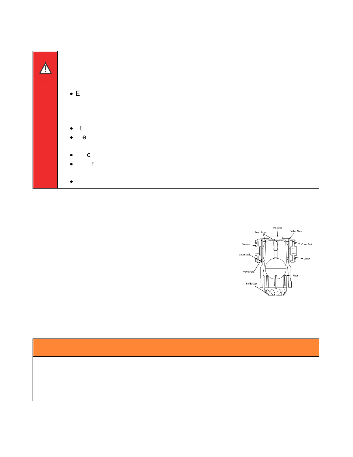
product flow. Air and vapor eliminators are set above the
product flow so that air in the system is pushed up into the
the cavity inside the air eliminator housing, out the valve plate
vent ports, through the piping, and into a storage tank (see
"Vent Ports Open" figure).
As air is evacuated from the system, the liquid level inside the
air eliminator cavity is allowed to rise and push the float up.
As the float moves up, it presses the reed strips against the
valve plate sealing the vent ports and preventing product from
passing through the piping and into the storage tank. If more
air enters the system, it will rise to the top of the air eliminator
cavity. The air will accumulate there and push the liquid level,
and the float, lower. As the float falls, the reed strips pull
away from the vent ports, and air can be vented before it
enters the system.
27

Mechanical Air & Vapor Eliminators
8
Get the latest PDF manual: https://www.lcmeter.com/resources/technical/manuals
Mobile/online version of this manual: https://www.lcmeter.com/manuals
Air Check and Differential Valves
Air check and differential valves are spring loaded
valves on the outlet side of the meter. Most Liquid
Controls meter systems with an air eliminator also
have an air check or a differential valve. Air
eliminators and air-check (or differential) valves work
in conjunction to stop the flow of product through the
meter until the air is eliminated from the system. In
order to do this, the air eliminator and the valve are
piped together at installation.
Air-check (or differential) valves are normally closed,
but when the pump starts and pushes product into
the system, the valve spring will give way to the flow
pressure. In order to keep the valve closed when air
is being expelled from the air eliminator, the air from
the air eliminator is routed through the piping to the
back side of the valve spring. The combined force of
the expelled air and the strength of the spring keep
the valve closed until the air is eliminated.
Limited Bleed Valve Plates
After the air is eliminated and the reed strips pull
away from the vent ports, the air pressure on the
back side of the spring is relieved and the valve
opens. To avoid the system shock sustained by an
abruptly opened valve, the pressure must be
released slowly. In order to do this, a 1/32-inch bleed
hole has been drilled into one of the valve plates so
that it sits over a bypass port. The small bleed hole
gradually releases the pressure on the valve spring
allowing it to open it slowly.

Mechanical Air & Vapor Eliminators
9
Get the latest PDF manual: https://www.lcmeter.com/resources/technical/manuals
Mobile/online version of this manual: https://www.lcmeter.com/manuals
Storage Tank
Bypass ports provide a pathway through the mechanical air eliminator housing to allow air or
vapor to pass from one side of the air eliminator to the other while the valve plate vent ports
are sealed.
Limited Bleed Tee Assemblies
Some Liquid Controls mechanical air eliminator models are
designed without bypass ports in their housings (for
example, bulk plant air eliminators). For those models to
retain the functions of a limited bleed valve plate, a limited
bleed tee assembly can be installed in the piping.
Dual-Head Bulk Plant Air Eliminators
By employing two air eliminators–a high-mount air eliminator and a low-mount air eliminator–
dual-head bulk plant air eliminators save the metering system from shocks incurred by
recurring small slugs of air (or vapor) and prevent large slugs of air from passing by the air
eliminator and through the meter system.
Each time a standard air eliminator removes a small slug of air, it closes the downstream
differential valve. When the differential valve closes at a high flow rate, meter systems can
incur a significant hydraulic shock. Repeated shocks of this nature can shorten the life of the
metering system.
Dual-head bulk plant air eliminators have a high-mount air eliminator that eliminate small slugs
of air without stopping the product flow through the meter system to save the system from
shock. Dual-head bulk plant air eliminators also have a low-mount air eliminator to remove
large air slugs.
Occasionally, large slugs of air can overtake a standard air eliminator, and excess air can blow
by the air eliminator and pass through the meter–which can cause inaccurate metering. With a
dual-head bulk plant air eliminator and a differential valve as part of the metering system, the
float in the low-mount air eliminator drops in the presence of a large slugs of air, the differential
valve senses the presence of air as the pressure above and below the diaphragm, and the

Mechanical Air & Vapor Eliminators
10
Get the latest PDF manual: https://www.lcmeter.com/resources/technical/manuals
Mobile/online version of this manual: https://www.lcmeter.com/manuals
valve closes until the large slug of air is removed. When the float rises and the valve opens,
the high-mount air eliminator removes the remaining air in the vessel.
Dual-head bulk plant air eliminators require a
differential valve and they can only be mounted in
fixed installations. They are ideal for applications
when product is being metered into storage from a
truck or transport with a pump mounted on the truck.

Mechanical Air & Vapor Eliminators
11
Get the latest PDF manual: https://www.lcmeter.com/resources/technical/manuals
Mobile/online version of this manual: https://www.lcmeter.com/manuals
Single-Head Bulk Plant Air Eliminator with Optical Sensor
The Single-Head Bulk Plant Air
Eliminator with Optical Sensor performs
the same functions as the Dual-Head
Bulk Plant Air Eliminator. Both air
eliminators use a high mount air
eliminator to siphon air without stopping
the flow. But instead of a low-mount
mechanical air eliminator, the Single-
Head Bulk Plant Air Eliminator with
Optical Sensor uses an optical sensor to
identify large air slugs. When the optical
sensor identifies a large air slug, it
instantly signals an electronic preset or
register (Toptech MultiLoad presets or
Liquid Controls LectroCount registers).
The electronic device closes a
downstream control valve–which stops
the product flow–and the air slug is
quickly vented.
The optical sensor provides several advantages over its mechanical counterpart. The response
time of the optical sensor is much faster than pneumatic-based mechanical air eliminators.
The optical sensor has no moving parts or piping requirements, which can simplify installation
and maintenance.

Mechanical Air & Vapor Eliminators
12
Get the latest PDF manual: https://www.lcmeter.com/resources/technical/manuals
Mobile/online version of this manual: https://www.lcmeter.com/manuals
Specifications
Aluminum High-Mount Air & Vapor Eliminators
For use with aluminum M-5, M-7, M-10,
M-15, M-25, M-30, M-40, M-60 and M-
80 meters. Typically installed with
aluminum F7, F15, and F30 strainers.
·
Working Pressure = 150 PSI
·
Typical Products are Refined Fuels
NOTE: Consult the factory when certified
engineering drawings are required.
Dimensions shown are not suitable for
construction or modifications.

Mechanical Air & Vapor Eliminators
13
Get the latest PDF manual: https://www.lcmeter.com/resources/technical/manuals
Mobile/online version of this manual: https://www.lcmeter.com/manuals
High-Pressure Aluminum Air & Vapor Eliminators
For use with aluminum MA-4, MA-5, and
MA-7 and MA-15 meters. Typically
installed with the aluminum FA7 strainer.
·
Working Pressure = 350 PSI
·
Typical products are LPG and
Anhydrous Ammonia
NOTE: Consult the factory when certified
engineering drawings are required.
Dimensions shown are not suitable for
construction or modifications.

Mechanical Air & Vapor Eliminators
14
Get the latest PDF manual: https://www.lcmeter.com/resources/technical/manuals
Mobile/online version of this manual: https://www.lcmeter.com/manuals
Cast Iron High-Mount Air & Vapor Eliminators
For use with cast iron M-7 meters.
Typically installed with the cast iron F7
strainers.
·
Working Pressure = 150 PSI
·
Typical products are Chlorinated
Solvents
NOTE: Consult the factory when certified
engineering drawings are required.
Dimensions shown are not suitable for
construction or modifications.

Mechanical Air & Vapor Eliminators
15
Get the latest PDF manual: https://www.lcmeter.com/resources/technical/manuals
Mobile/online version of this manual: https://www.lcmeter.com/manuals
Stainless Steel High-Mount Air & Vapor Eliminators
For use with stainless steel M-5 class 8 and M-7
class 8 meters. Installed with stainless steel F7
class 8 strainers.
·
Working Pressure = 150 PSI
·
Typical products are Acidic Solutions
NOTE: Consult the factory when certified
engineering drawings are required. Dimensions
shown are not suitable for construction or
modifications.

Mechanical Air & Vapor Eliminators
16
Get the latest PDF manual: https://www.lcmeter.com/resources/technical/manuals
Mobile/online version of this manual: https://www.lcmeter.com/manuals
Steel Air & Vapor Eliminators
For use with MS, MSAA, and MSA series
steel case meters. Installed with FS, FSAA,
and FSA steel series strainers.
·
Working Pressure = 150 PSI, 275 PSI
and 300 PSI PSI (Three products are
available)
·
Typical products are Refined Fuels and
Light Hydrocarbons
NOTE: Consult the factory when certified
engineering drawings are required.
Dimensions shown are not suitable for
construction or modifications.

Mechanical Air & Vapor Eliminators
17
Get the latest PDF manual: https://www.lcmeter.com/resources/technical/manuals
Mobile/online version of this manual: https://www.lcmeter.com/manuals
Steel Bulk Plant Air Eliminators
For use with aluminum M or MS series
meters.
Choices of 3, 4, 6 and 8 inch ANSI flanged
connections. Offered in single-head, dual-
head, and single-head with optical sensor
models to provide high-venting capacity for
metering into storage systems.
·
Working Pressure = 150 PSI
·
Typical products are Refined Fuels
·
Optical Sensor - Power Input: +10 to
+28VDC, 0.5A maximum
NOTE: Consult the factory when certified
engineering drawings are required. Dimensions
shown are not suitable for construction or
modifications.

Mechanical Air & Vapor Eliminators
18
Get the latest PDF manual: https://www.lcmeter.com/resources/technical/manuals
Mobile/online version of this manual: https://www.lcmeter.com/manuals
Steel Low-Mount Air Eliminators
For use with filter/separators.
·
Working Pressure = 150 PSI
·
Typical products are Aviation Fuels
NOTE: Consult the factory when certified
engineering drawings are required. Dimensions
shown are not suitable for construction or
modifications.
This manual suits for next models
9
Table of contents
Other Idex Industrial Equipment manuals
Popular Industrial Equipment manuals by other brands

RGB Technology
RGB Technology 106-01-02 Technical and Operational Documentation

Techniks
Techniks SHRINKPRO Operation manual

SCHUNK
SCHUNK PPU-E Assembly and operating manual

Nakanishi
Nakanishi NRR3060-QC Operation manual

ABB
ABB HT614530 Operation manual

Horizon Fitness
Horizon Fitness PJ-110 instruction manual

Pfannenberg
Pfannenberg PA 10/ 20 quick guide

IPC
IPC V 200 MD Silent-H instruction manual

A-PLUS AUTOMATION
A-PLUS AUTOMATION A3-P Instruction handbook

Grundfos
Grundfos PHT A N Installation and operating instructions

Pfannenberg
Pfannenberg PWS Series Installation, operation and service manual

ABB
ABB HT578272 Operation manual