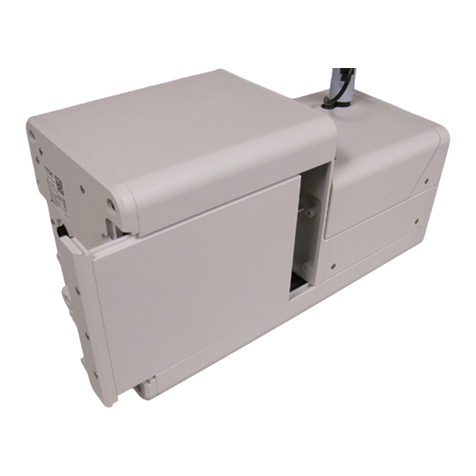
Idexx Filta-Max xpress Manual

Filta-Max xpress
Pressure Elution Station
Operator’s Guide

2Filta-Max xpress Operator’s Guide
Proprietary rights notice
Information in this document is subject to change without notice. Companies, names, and data used in examples are fictitious unless
otherwise noted. No part of this document may be reproduced or transmitted in any form or by any means, electronic, mechanical, or
otherwise, for any purpose, without the express written permission of IDEXX Laboratories. IDEXX Laboratories may have patents or
pending patent applications, trademarks, copyrights, or other intellectual or industrial property rights covering this document or subject
matter in this document. The furnishing of this document does not give a license to these property rights except as expressly provided
in any written license agreement from IDEXX Laboratories.
© 2019 IDEXX Laboratories, Inc. All rights reserved. • 06-9020469-00
*Filta-Max xpress and Filta-Max are trademarks or registered trademarks of IDEXX Laboratories, Inc. in the United States and/or other
countries. All other product and company names and logos are trademarks of their respective holders.

3Filta-Max xpress Operator’s Guide
Contents
Introduction.............................................................................................................................................5
Safety...........................................................................................................................................................5
Compliance .................................................................................................................................................5
Warnings......................................................................................................................................................6
Components ...........................................................................................................................................7
Pressure Elution Station...............................................................................................................................7
Pressure Elution Station system..................................................................................................................8
Specifications .........................................................................................................................................9
Technical specifications...............................................................................................................................9
Environmental conditions ............................................................................................................................9
Equipment, consumables, and reagents...............................................................................................9
Equipment and consumables not supplied by IDEXX................................................................................9
Equipment and consumables available from IDEXX ..................................................................................9
Setting up the Pressure Elution Station ..............................................................................................10
Location .....................................................................................................................................................10
Power connection ......................................................................................................................................10
Connecting the air supply..........................................................................................................................10
Using your facility’s air supply ...................................................................................................................10
Connecting an air compressor to the hose kit ..........................................................................................10
Checking the pressure regulator setting ...................................................................................................11
Assembling sampling and filtering equipment ...................................................................................12
Sampling....................................................................................................................................................12
Operating pressure....................................................................................................................................12
Assembling the Filter Module and filtering the sample .............................................................................13
Operating the Pressure Elution Station...............................................................................................13
Preparing the buffer solution .....................................................................................................................13
Performing the initial system check...........................................................................................................14
Transferring Filter Modules to an alternative housing................................................................................15
Understanding the control panel...............................................................................................................15
Eluting the sample.....................................................................................................................................16
Concentrating the eluates and resuspending the pellet before IMS ........................................................17
Purging the buffer solution ........................................................................................................................19

4Filta-Max xpress Operator’s Guide
Maintenance and cleaning ...................................................................................................................20
After each elution .............................................................................................................................. 20
On a daily basis................................................................................................................................. 20
On a monthly basis ........................................................................................................................... 20
Servicing the Pressure Elution Station.......................................................................................................21
Storing the Pressure Elution Station ...................................................................................................22
Limited warranty ...................................................................................................................................24
Appendix A: Consumables...................................................................................................................25
Appendix B: Air supply requirements .................................................................................................26
Appendix C: Troubleshooting ..............................................................................................................27
Contacting IDEXX Technical Service ...................................................................................................28

5Filta-Max xpress Operator’s Guide
Introduction
The Filta-Max xpress* Pressure Elution Station is used to automate the elution of
Cryptosporidium spp. oocysts and Giardia spp. cysts from Filta-Max xpress* Filter Modules and
Filta-Max* Filter Modules.
The Pressure Elution Station and elution procedures are designed for use with 10–1,000 L water
samples.
Note: The recovery of Giardia spp. cysts from large-volume finished water samples may be affected
by residual chlorine in the sample.1
Safety
For your safety, read this guide thoroughly before using the Filta-Max xpress Pressure Elution
Station.
IDEXX recommends that you perform your own safety assessments of the Filta-Max xpress
Pressure Elution Station and follow your own in-house health and safety guidelines.
All water samples, spills, splashes, aerosols, filters, and eluates should be handled with at least the
same precautions as the water source with regard to biohazards. The Pressure Elution Station does
not render such samples to be safe and, in fact, concentrates the biological risks into the eluate.
Ensure that the connections between the Filter Housings and any sampling equipment are capable
of withstanding the operating pressure of the elution station.
The Filta-Max xpress Pressure Elution Station weighs approximately 86 lb (38 kg). Be sure to use
a table or bench that can support the weight of the instrument. Two people are required to lift the
instrument. Do not use the pneumatic fittings that extend out of the back panel as a handle for
lifting. This will loosen the fittings and potentially introduce an air leak.
Ensure that you understand all instructions and safety precautions listed in this manual. If you have
any questions, contact IDEXX Technical Service as follows:
• In the United States call +1 800 321 0207 or email watertechnicalservice@idexx.com.
• In Europe call +44 (0)1638 676800 or email emeatechsupport@idexx.com.
Compliance
• European Union: EN61010-1: 2010 and EN-2-040
• US/MET NRTL Mark: UL 61010-1, 3rd Edition and UL 61010-2-040
• Canada/MET “c” Mark: CSA C22.2 No. 61010-1. 3rd Edition and CSA C22.2 No. 61010-2-040
• EN 61326-1:2013 PART 1: EU EMC Directive: EN 61000-4-3 Radiated Immunity
• 47: CFR Part 15, subpart B, Class A (FCC)
• ICES-003 Issue 4, February 2004, Class A
• CNS13438 (C6357): 2006: Taiwan/BSMI: CISPR32
• CNS13438 (C6357): 2006: Australia/NZ: Market Access
• VCCI V-1/93.11, V-2/97.04, V-3/97, R-1216, and C-1279 Class A ITE

6Filta-Max xpress Operator’s Guide
Warnings
Warnings are designated by an exclamation mark inside a triangle and are highlighted in bold.
Warnings are also displayed as labels on the Filta-Max xpress Pressure Elution Station at strategic
locations.
• Observe all warning labels.
• Never remove warning labels.
• Never operate a damaged or leaking unit.
• Always turn off the power and disconnect the power cord prior to performing any service or
routine maintenance.
• Never operate the Filta-Max xpress Pressure Elution Station with a damaged power cord.
When replacing the power cord, use only power cords with adequate rating.
• The Pressure Elution Station is designed with an electrical ground system. Never defeat any
part of the protective earthing.
• Do not attempt to disassemble the unit. Refer all service and repairs to a qualified service
technician.

7Filta-Max xpress Operator’s Guide
Components
Pressure Elution Station
Emergency
stop button
Green LED: power
supply indicator
Red LED:
• Steady = Machine ready
• Flashing = System fault indicator
Figure 1b. Switches and buttons
Filter Housing/outlet
diverter assembly sensor
Collection vessel
cylinder
Collection
vessel sensor
Collection vessel
holder
Figure 1c. Sensors, fittings, and vessels
Figure 1. Pressure Elution Station
without a Filter Housing and diverter
assembly
Socket head
cap screw
Pressure
chamber lid
Buffer inlet
with flow meter
Pressure
gauge fitting
High-pressure
gauge
Low-pressure
gauge
Pressure
chamber body
Air inlet with
relief valve
Pressure chamber
purge valve
Swagelok quick-
connect (QC) stem
Figure 1a. Pressure chamber and gauges
1a
1b
1c
Green LED: power
supply indicator
Touch-screen
control panel
Four-button
control panel
Control panel

8Filta-Max xpress Operator’s Guide
Pressure Elution Station system
• Filta-Max xpress Pressure Elution Station
• Buffer Reservoir Kit (one 10 L bottle and one 4 L bottle with lids)
• Outlet diverter (5-pack kit)
• Hose kit
• Accessory kit:
– Power pack
–Filta-Max xpress Operator’s Guide
– Pressure chamber O-ring
– Tool kit (2 hex wrenches, quick-connect fitting, screwdriver)
Figure 2. Pressure Elution Station with a
Filter Housing and diverter assembly attached
Figure 2a. Filta-Max xpress Filter Housing and
diverter assembly
Swagelok quick-
connect (QC) body
Filta-Max xpress
Filter Housing
Swagelok
quick-flow (QF) body
Swagelok quick-flow
(QF) stem
Outlet diverter
assembly
Sensor ring

9Filta-Max xpress Operator’s Guide
Specifications
Technical specifications
• Dimensions: 28" H x 14" D x 20.5" W (711 mm H x 356 mm D x 521 mm W)
• Weight: 86 lb (37.7 kg)
• Minimum input pressure: 65 psig (4.5 bar)
• Maximum input pressure: 150 psig (10.3 bar)
• Working pressure: 72.5 to 116 psig (5.0 to 8.0 bar)
• Supply voltage (through an external power source):
100–240 V AC @ 47–63 Hz, output 4.2–5.0 A @ 24 V DC (limited power source only)
• Pressure Elution Station current rating: 4.2–5.0 A @ 24 V DC
Environmental conditions
• Intended for indoor use only
• Temperature range: ambient temperature of 16°C–24°C
• Humidity range: 0%–80% relative humidity
• Maximum altitude: 2,000 m (6,562 feet)
• Pollution degree: 2
• Overvoltage protection: category 2
Equipment, consumables, and reagents
The following additional equipment, consumables, and reagents are necessary for filter elution.
Equipment and consumables not supplied by IDEXX
• Sampling pump that is suitable for use with the sampling fittings or a suitable sampling rig for
use with a pressurized water supply
• Platinum cured tubing (13–15 mm internal diameter) suitable for use with the sampling pump
or pressurized water supply
• 500 mL centrifuge tubes and/or 50 mL conical centrifuge tubes (for double centrifugation)
• Centrifuge with capacity for 500 mL centrifuge tubes and/or 50 mL conical centrifuge tubes
that is capable of reaching 2,000 × g (g-force or relative centrifugal force)
• Alcohol-soaked wipes, laboratory grade ethanol, or sodium hypochlorite solution
• Reagents:
– Phosphate buffered saline (PBS)
– Polyoxyethylene sorbitan monolaurate (TWEEN* 20)
For additional information on the reagents, see "Preparing the buffer solution" on page 13.
Equipment and consumables available from IDEXX
These items may be purchased from IDEXX. For more information, see Appendix A.
• Filta-Max xpress Filter Housing
• Filta-Max xpress Filter Module or Filta-Max Filter Module
• Filta-Max xpress Sampling Kit
• Filta-Max xpress Housing Conversion Kit

10 Filta-Max xpress Operator’s Guide
Setting up the Pressure Elution Station
Location
The Filta-Max xpress Pressure Elution Station and buffer reservoir bottle should be placed on a
sturdy bench or laboratory surface capable of supporting both their weight and the force required to
install and remove the Pressure Elution Station housing and fittings.
Power connection
• Connect the low-voltage cable to the inlet power socket on the back panel of the Pressure
Elution Station.
• Connect the provided power supply to a suitable electrical outlet using a power cord with
the appropriate rating (18 AWG/.75 mm2). The external power supply will function normally
between 100 and 240 V AC at 47–63 Hz.
Connecting the air supply
Compressed air is required for the Pressure Elution Station to function properly because it supplies
the air pressure needed to elute the Filter Modules. IDEXX supplies a hose kit that lets you connect
either your facility’s air supply or a compressor to the Pressure Elution Station. The hose kit consists
of a 12-foot self-retracting hose and connector.
Compressed air must be oil and moisture free. IDEXX can supply an external air filter that attaches
to the rear of the Pressure Elution Station to remove oil and moisture from the air.
Using your facility’s air supply
If you use your own facility’s air supply, check to ensure that the outlet pressure is between 5.0 bar
and 8.0 bar (72.5 and 116 psig). The air supply must have a sufficient capacity to perform elution
cycles whilst remaining above 5.0 bar (72.5 psig). Your facility’s air supply may require filters to
remove oil and moisture.
Use the quick-connect fittings supplied with the Pressure Elution Station or other appropriate fittings
to connect the air supply. The connection is made at the back of the Pressure Elution Station at the
air line inlet connector.
Before connecting and applying air pressure to the Pressure Elution Station, ensure that the
lockable air inlet valve is in the OFF (EXH) position by turning it clockwise. When the connection
has been made and there is pressure to the Pressure Elution Station, turn the lockable air inlet valve
counterclockwise to the ON (SUP) position.
Connecting an air compressor to the hose kit
Note: The compressor must be oil free.
1. Prepare the air compressor for use according to its operating instructions.
Note: The components and their respective locations on the air compressor may vary with
the model. Polytetrafluroethylene (PTFE) tape, plumbing tape, or other appropriate sealant is
recommended at all threaded connections.
2. Connect the swivel end of the 12-foot self-retracting hose (found in the Filta-Max xpress
Hose Kit) to the air compressor’s filter, which is attached to the regulator.
3. Ensure that the lockable air inlet valve on the Pressure Elution Station is in the OFF (EXH)
position by turning it clockwise.
4. Connect the other end of the hose to the air line inlet connector on the Pressure Elution
Station.

11 Filta-Max xpress Operator’s Guide
5. Follow the compressor’s instruction manual to modulate the outlet pressure between 5.0 and
8.0 bar (72.5 and 116 psig).
6. Connect the air compressor’s power cord to a suitable electrical outlet.
7. Turn the air compressor’s ON/OFF switch to ON or AUTO.
8. Allow the air pressure in the receiver to build to at least 5.0 bar (72.5 psig).
Note: With the air compressor in auto mode, the motor will automatically stop when the
pressure reaches a preset maximum and will restart when the pressure drops below a preset
minimum. You can monitor the pressure in the receiver via the receiver pressure gauge.
The minimum pressure required for use with the Pressure Elution Station is 5.0 bar. The air
compressor should have a sufficient flow rate to maintain pressure above 5.0 bar during use.
9. To increase or decrease the outlet pressure, turn the pressure regulator’s adjustment
according to the manufacturer’s instructions.
10. When you have attached the quick-connect fittings to the Pressure Elution Station and there is
pressure, turn the lockable air inlet valve counterclockwise to the ON (SUP) position. The air
supply is now ready for use with the Pressure Elution Station.
Note: If the pressure from the air supply falls below 5.0 bar (72.5 psig), there will be
insufficient pressure to complete an elution cycle and a Low Pressure error message will be
displayed. When processing multiple samples, be sure to monitor the pressure.
Checking the pressure regulator setting
With pressure supplied to the Pressure Elution Station and the lockable air inlet valve in the ON
position, the high-pressure gauge should read approximately 5.0 bar (72.5 psig), while the
low-pressure gauge should read approximately 0.38 bar (5.5 psig).
If the gauge readings are not correct, contact IDEXX Technical Service for assistance.
Note: The low-pressure regulator, a precision-regulator located within the Pressure Elution Station,
will always release a small amount of air; a slight hissing sound is normal.

12 Filta-Max xpress Operator’s Guide
Assembling sampling and filtering equipment
Sampling
You can collect samples at the point of source or in the laboratory. IDEXX provides the equipment
necessary to perform sample filtration using the Filta-Max xpress Filter Modules or
Filta-Max Filter Modules, Filter Housings, and sampling and elution fittings (see Appendix A).
To set up the sampling equipment:
1. Connect the Swagelok* quick-flow (QF) body
to the Swagelok hose-tail fitting to create the
sampling inlet. Use PTFE tape to help form a
seal.
2. Attach the sampling inlet to a hose that is
connected to the water supply or a pump.
If a pump (diaphragm, peristaltic, etc.) is used
to sample water, it must be installed upstream of
the Filter Housing.
Note: A hose clip is required to ensure that the
seal between the hose and the sampling inlet is
watertight.
3. Connect the Swagelok quick-connect (QC)
stem to a Swagelok hose-tail fitting to create the
sampling outlet. Use PTFE tape to help form a
seal.
4. Attach the sampling outlet to a hose that is connected to a suitable waste outlet.
Note: A hose clip is required to ensure that the seal between the hose and the sampling outlet
is watertight.
Operating pressure
A head pressure of 0.5 bar (7.5 psig) is required to generate flow through the Filter Module. The
recommended operating pressure is 5.0 bar (72.5 psig), which should generate a flow of 1–2 liters
per minute (LPM). The operating pressure should not exceed 8.0 bar (116 psig). Pressure spikes
should be avoided where possible.
Hose Hose-tail
fitting QF body
Sampling inlet
Hose
Hose-tail
fitting
QC stem
Sampling outlet

13 Filta-Max xpress Operator’s Guide
Assembling the Filter Module and filtering the sample
1. Place the Filter Module bolt-head down into a
Filter Housing.
2. Tighten the lid until the two serial-numbered tag
holes are aligned and a gap of approximately
0.5 mm is left between the lid and the base.
3. Tighten the lid an additional 1/8 of a turn past
this point and then back again to align the tag
holes. This step correctly seats the O-ring.
4. Connect the Filter Housing to the sampling
setup by connecting the QF stem to the
sampling inlet and the QC body to the sampling
outlet.
Note: The QC body on the Filter Housing is self-
sealing and does not require an additional seal.
5. Turn on the water supply and restrict the flow
to 1–2 liters per minute using a suitable flow
restrictor located downstream of the Filter Housing.
6. When sampling is complete, turn off the water supply.
7. Disconnect the Filter Housing from the sampling setup, and seal the QF stem using the
stopper provided.
Note: You can perform sample filtration in suitable Filter Housings fitted with connectors other
than those required for use with the Pressure Elution Station. In this case, the Filter Module must
be transferred to a Filter Housing suitable for use with the Pressure Elution Station. For more
information, refer to “Eluting the Sample.”
Operating the Pressure Elution Station
Preparing the buffer solution
Before you begin mixing the buffer solution, determine the amount of solution required for the
number of samples you are going to elute. In addition, 400 mL of buffer solution is required for the
initial system check of the Pressure Elution Station and for each subsequent elution.
Phosphate buffered saline solution may be purchased in a ready-made solution or may be
prepared using individual ingredients as follows:
• Sodium chloride 8.0 g/L
• Potassium chloride 0.2 g/L
• Disodium hydrogen phosphate 1.15 g/L
• Potassium dihydrogen phosphate 0.2 g/L
To prepare 1 L of the buffer solution:
1. In a suitable container, add the individual ingredients for PBS to 1 L of reagent-grade water.
2. Place the container on a magnetic stirrer plate.
3. Add 0.1 mL of TWEEN 20, and mix for at least 10 minutes or until dissolved.
Note: TWEEN 20 is very viscous and requires careful pipetting. Wipe the outside of the pipette
with a paper towel/tissue to ensure the correct amount is dispensed.
Sample flow
through Filter
Housing
QC body
Filter Module
Bolt end
Filter Housing lid
Filter Housing
base
QF stem

14 Filta-Max xpress Operator’s Guide
To fill the buffer reservoir:
The Buffer Reservoir Kit includes one 10 L bottle and one 4 L bottle. Because of the performance of
the initial system check and buffer purge, two reservoirs are required. IDEXX suggests that the 10 L
reservoir be used for the buffer solution and the 4 L reservoir be used for reagent-grade water.
The buffer reservoirs provided by IDEXX are manufactured from heavy-duty high density
polyethylene (HDPE). Only heavy-duty reservoirs should be used in this application.
1. After mixing the buffer solution, decant it into a buffer reservoir bottle.
2. The closure cap is attached to the Pressure Elution Station by an air and liquid feed line.
Attach the buffer reservoir to the cap.
3. Ensure there is a tight seal between the reservoir body and the closure cap.
Note: When the closure cap is new, the integral seal is quite stiff and may be difficult to
tighten. After several uses, tightening the closure cap will become easier. Vacuum grease can
be used to help make tightening easier.
Performing the initial system check
Before performing sample elution, you must perform an initial system and integrity check to ensure
that no error messages are generated during sample elution. This initial step also serves to purge
reagent-grade water from the lines and replace it with buffer solution.
1. Place a blank Filter Module into a Filta-Max xpress Filter Housing. (See "Assembling the
Filter Module and filtering the sample" on page 13 for instructions.)
2. This blank Filter Module can be reused for 1 month when performing the initial system check
or when purging buffer solution from the system (see "Purging the buffer solution" on page
19 for more information).
3. Complete steps 1–8 of "Eluting the sample" on page 16.
4. The Pressure Elution Station will run through a complete elution cycle. If no errors are
generated, continue with steps 3–6 below. If a pressure or flow error occurs, refer to
Appendix C.
5. At the end of the elution cycle, discard the liquid from the centrifuge tube.
6. You can reuse the centrifuge tube when performing the initial system check or when purging
buffer solution from the system.
7. Disconnect the Filter Housing from the Pressure Elution Station, and then disconnect the
outlet diverter fitting from the Filter Housing.
8. Clean the Swagelok QC stem on the elution station with alcohol-soaked wipes.
9. Because the system uses positive pressure to elute filters, there is limited to no risk of sample-
to-sample cross-contamination.2
10. Proceed to “Transferring Filter Modules to an alternative housing” and/or “Eluting the sample.”

15 Filta-Max xpress Operator’s Guide
Transferring Filter Modules to an alternative housing
If sample filtration was performed in a housing other than one suitable for use with the Pressure
Elution Station, you must transfer the Filter Module to an appropriate housing before elution.
1. Remove the lid of the housing used for sampling or the transport container, and carefully
transfer the Filter Module, bolt-head down, to a Filta-Max xpress Filter Housing, which will be
used in the Pressure Elution Station.
2. Pour any remaining liquid from the Filter Housing or container into the centrifuge tube.
3. Rinse the Filter Housing or container with reagent-grade water, and transfer this rinse to the
centrifuge tube. The total volume transferred to the centrifuge tube should not exceed
50 mL.
4. Seal the second housing as described in "Assembling the Filter Module and filtering the
sample" on page 13.
Understanding the control panel
Instruments with a four-button control panel:
The menu screen displays the following:
• F1 starts the elution cycle.
• F2 checks the pressure.
With the buffer reservoir cap sealed, press and hold the F2 button for 3 or more seconds.
Listen for any air leaks, and monitor the low-pressure gauge for pressure changes.
• F3 resets the cycle counter.
Press and hold the F3 button for 3 seconds to display the number of cycles completed (i.e.,
the number of samples eluted).
Press and hold the F3 button for 5 seconds to reset the counter to zero.
• F3 and F4 display total cycles run (this counter is not resettable).
Press and hold the F4 button, and then press and hold the F3 button to display the total
number of cycles run on the Pressure Elution Station.
Instruments with a touch-screen control panel:
The menu screen displays the following:
• Start starts the elution cycle.
• Pressure Test displays the Buffer Reservoir Pressure Test screen.
From the Buffer Reservoir Pressure Test screen:
– Exit returns to the start screen.
– Start Test starts the buffer reservoir pressure test.
– With the buffer reservoir cap sealed, press and hold the Start Test button for 3 or more
seconds. Listen for any air leaks, and monitor the low-pressure gauge for pressure
changes.
– Line Purge starts the line purge process
Note:
A Filter Housing without a Filter Module must be in place.
A centrifuge tube must be in the centrifuge tube holder.
The buffer reservoir must be empty.
The buffer reservoir cap must be securely sealed.

16 Filta-Max xpress Operator’s Guide
Press and hold the Line Purge button. This will lift the centrifuge tube and purge the
fluid from the lines. Continue to hold the Line Purge button until all the fluid is purged,
which usually takes about 10 seconds. Release the Line Purge button, press the Exit
button to return to the start screen, and then remove the centrifuge tube.
• User Cycles resets the cycle counter.
Press the User Cycles button to display the Tests Count screen. This screen shows the
number of cycles completed (i.e., the number of samples eluted).
From the Tests Count screen:
– Exit returns to the start screen.
– Reset resets the cycle counter to zero. Press and hold the Reset button for 5 seconds
to reset the counter.
• Total Cycles displays the total cycles run (this counter is not resettable).
Press the Total Cycles button to display the total number of cycles run on the Pressure
Elution Station.
From the Cycle Count screen:
– Exit returns to the main start screen.
– Wash Time shows the most recent wash cycle time in minutes.
Eluting the sample
1. Turn on the Pressure Elution Station by depressing the on/off switch to the I position. The
green LED (power) and the red LED (machine ready) are lit.
The on/off switch is located on the back of the Pressure Elution Station.
2. Remove the lid from a 500 mL centrifuge tube, and place it into the collection vessel holder.
3. With the Filter Housing QF stem facing upward, attach the outlet diverter fitting to the QF stem
by pulling back the collar and pushing the fittings together.
4. Turn the Filter Housing over, and place the outlet diverter over the centrifuge tube to catch any
sample that may leak.
5. Connect the Filter Housing QC body to the QC stem on the Pressure Elution Station by
pushing the fittings together.
Note: If you have already performed a system check, you can skip steps 6–7 and proceed
directly to step 8.
6. Check that the air supply is set up correctly, the air line is connected to the Pressure Elution
Station, and the air inlet valve is open.
Note: Compressed air must be used with the Pressure Elution Station.
7. Ensure that there is sufficient buffer solution in the buffer reservoir bottle and that the seal
between the closure cap and the reservoir bottle is airtight.
8. To start the filter elution cycle:
On the four-button control panel press F1.
On the touch-screen control panel press Start.
IMPORTANT: During the elution cycle, the collection vessel holder and centrifuge tube are
lifted into position. Do not override the door sensors as they protect you from pinch points
produced by this movement. If the door sensors fail to function, do not place your hands or
any objects in this area. Contact IDEXX Technical Service for assistance.
9. At the end of the elution cycle, disconnect the Filter Housing from the Pressure Elution Station
by pushing the collar on the QC body upwards while pulling the Filter Housing down; then
disconnect the outlet diverter fitting from the Filter Housing.

17 Filta-Max xpress Operator’s Guide
10. Open the Filter Housing, remove the Filter Module, and discard the Filter Module according to
appropriate disposal regulations.
IMPORTANT: All Filter Modules should be autoclaved according to your standard autoclave
waste disposal cycle.
11. Cap the centrifuge tube, and remove it from the collection vessel holder.
Note: The Pressure Elution Station contains several sensors. The Pressure Elution Station will
not start an elution cycle if the centrifuge tube, the Filter Housing, or the outlet diverter are not
in place. At the end of an elution cycle, the Pressure Elution Station will not start the next cycle
unless the centrifuge tube is removed from the collection vessel holder and replaced with a
fresh tube.
12. Clean the QC stem on the Pressure Elution Station with alcohol-soaked wipes.
13. Proceed with subsequent sample elutions.
Concentrating the eluates and resuspending the pellet before IMS
After eluting the samples, you must concentrate the eluates further by centrifugation before
purifying them by immunomagnetic separation (IMS).
Centrifuge requirements (e.g., Hettich* Rotanta 460)
• Swing-out rotor
• Inserts and support cushions for 500 mL centrifuge tubes
• In good working order, with bucket supports lightly greased
Centrifuge setup
• Locate centrifuge to minimise vibration.
• Set RCF to 2000 × g.
• Set acceleration to maximum and deceleration to minimum, with the minimum amount of
braking possible.
• Set time to 15 minutes, excluding ramp-up time.
To concentrate the eluates:
1. Balance the centrifuge tubes (collected in step 11 of "Eluting the sample" on page 16),
the cushions, and the centrifuge buckets to within 0.5 g of each other.
Note: Failure to balance the tubes correctly can result in centrifuge imbalance and can affect
the target sedimentation efficiency due to excessive vibration.
2. Centrifuge the samples at 2,000 × g for 15 minutes (not including the time taken to reach
2000 × g), allowing the centrifuge to coast to a stop at the end of centrifugation. DO NOT
USE THE BRAKE.
Note: The deceleration profiles of different centrifuge models can vary. For optimal
performance, the centrifuge should not be braked during deceleration. Check the operator’s
guide provided with the centrifuge or the centrifuge vendor’s technical service department for
the centrifuge deceleration profile. Deceleration via braking can reduce method performance
during this procedure.
The sample separates into supernatant and concentrated eluates, which often form a pellet at
the bottom of the tube.

18 Filta-Max xpress Operator’s Guide
3. First aspiration:
a. Aspirate the supernatant immediately following centrifugation, leaving 25 mL of the
supernatant in the tube.
b. Once aspiration is complete, vortex the sample at full speed for 20 seconds to disperse
the pellet (extend vortexing time if needed).
c. Swirl and pour into a 50 mL centrifuge tube.
d. Add 10 mL reagent-grade water to the 500 mL centrifuge tube (this acts as a rinse).
e. Vortex the sample at full speed for 20 seconds.
f. Swirl and pour into the 50 mL centrifuge tube.
g. Add a second 10 mL reagent-grade water rinse to the 500 mL centrifuge tube.
h. Vortex the sample at full speed for 20 seconds.
i. Swirl and pour into the 50 mL centrifuge tube.
4. Second centrifugation:
Perform a second centrifugation of the 50 mL centrifuge tube containing your sample, using
the following centrifuge setup:
Centrifuge requirements (e.g., Hettich Rotanta 460)
• Swing-out rotor
• Inserts and support cushions for 50 mL centrifuge tubes
• In good working order, with bucket supports lightly greased
Centrifuge setup
• Locate centrifuge to minimize vibration.
• Set RCF to 1500 × g.
• Set acceleration to maximum and deceleration to minimum, with the minimum amount of
braking possible
• Set time to 15 minutes, excluding ramp-up time.
5. Second aspiration of supernatant:
• Carefully remove the 50 mL tube from the centrifuge.
• Aspirate to the 3 mL mark on the 50 mL tube.
• Perform IMS on the sample as soon as possible.
To resuspend the pellets:
1. From the centrifuge tube, aspirate the sample supernatant leaving approximately 7–8 mL in
the tube.
Notes:
• Hold the pipette in the center of the tube, and aspirate the sample from the surface of the
liquid. Avoid disturbing the pellet.
• Use a wide bore pipette (such as a 5 mL serological pipette) or equivalent attached to a
vacuum source.
• Do not exceed a vacuum of -0.5 psig. The flow rate during this procedure should be
approximately 200 mL per minute (+/- 20 mL).
• IDEXX suggests using a peristaltic pump attached to a waste trap for this procedure.
2. Resuspend the pellet by vortexing the sample for 20 seconds; extend the vortex time if
required.

19 Filta-Max xpress Operator’s Guide
3. Transfer the sample to an L10 tube using a suitable pipette primed with buffer solution.
Note: Priming, by drawing up buffer into the pipette and subsequently expelling it, prevents
any target organisms from sticking to the wall of the pipette.
4. Rinse the sides of the centrifuge tube twice with half the remaining volume of reagent-grade
water, transferring each of these wash volumes to the same L10 tube. For example, if the
volume remaining in the centrifuge tube is 7 mL, perform two rinses each with 1.5 mL of
reagent water.
5. Perform IMS according to appropriate procedures, for example, U.S. EPA Method 1622/1623,
Microbiology of drinking water (2010)-Part 14-Methods for the isolation, identification and
enumeration of Cryptosporidium oocysts and Giardia cysts or other appropriate guidelines or
manufacturer’s instructions.
Purging the buffer solution
When all the Filter Modules have been eluted, you must remove any remaining buffer solution from
the lines of the Pressure Elution Station by purging the system with reagent-grade water.
Note: If sample elution is performed infrequently during a day—for example, early morning and late
afternoon—it is advisable to perform a buffer purge between elution events. This will increase the
volume of buffer solution required.
1. Load a blank Filter Module into a Filta-Max xpress Filter Housing. (See "Assembling the Filter
Module and filtering the sample" on page 13 for instructions.)
This blank Filter Module can be reused for one month to perform the initial system check or to
purge buffer solution from the system.
2. Complete steps 1–8 of "Eluting the sample" on page 16.
3. When performing a buffer solution purge, replace the buffer solution with reagent-grade water.
At the end of the elution cycle, discard the liquid from the centrifuge tube.
The centrifuge tube can be reused to perform the initial system check or to purge buffer
solution from the system.
4. Disconnect the Filter Housing from the Pressure Elution Station, and then disconnect the
outlet diverter fitting from the Filter Housing. The lines are now filled with reagent-grade water.
5. Clean the Swagelok QC stem on the Pressure Elution Station with alcohol-soaked wipes.
Because the system uses positive pressure to elute filters, there is limited to no risk of
sample-to-sample cross-contamination.2

20 Filta-Max xpress Operator’s Guide
Maintenance and cleaning
Follow the guidelines below when decontaminating the Filta-Max xpress system.
After each elution
• Clean the QC stem on the Filta-Max xpress Elution Station using an alcohol-soaked wipe or
equivalent.
• Decontaminate the sampling kit, outlet diverter fittings, and the Filter Housing by soaking
them in warm (40°C–60°C) water containing laboratory-grade detergent for 15–30 minutes.
Then manually clean the equipment using a bottle brush or similar device, and rinse with (oo)
cyst-free finished water and then with reagent-grade water.
• Should more stringent decontamination be required, equipment may be soaked for 30
minutes in a 6% solution of sodium hypochlorite (60 mL of household bleach in 1 L of water).
Then manually clean the equipment using a bottle brush or similar device, and rinse with (oo)
cyst-free finished water and then with reagent-grade water.
• Relubricate and/or replace all O-rings, as required.
On a daily basis
• Clean the surfaces of the Filta-Max xpress Pressure Elution Station with laboratory disinfectant
or alcohol-soaked wipes.
• Clean the metal base plate and back plate (inside the door) using laboratory disinfectant or
alcohol-soaked wipes. Keep the inside of the machine as clean and dry as possible; remove
any spills between samples.
Note: With the air supply turned off, you can raise the collection vessel holder to improve
access to the base plate.
On a monthly basis
If the Pressure Elution Station is not used for 2 weeks, then you should also clean the pressure
chamber, following the steps below. The following tools are required and are supplied with each
Filta-Max xpress Pressure Elution Station as part of the accessory kit:
Angled screwdriver
Large 5/16" hex wrench
Small 5/64" hex wrench
1. Remove the four screws from the burgundy lid/cover using the small hex wrench provided,
and then remove the lid/cover of the Pressure Elution Station.
Table of contents
Other Idexx Laboratory Equipment manuals
Popular Laboratory Equipment manuals by other brands
BIO RAD
BIO RAD PowerPac Universal Power Supply instruction manual
Christ
Christ Epsilon 2-6D LSCplus operating manual

cytiva
cytiva AxiChrom Master 300 unpacking instructions
NPI
NPI ISO-STIM 01B Operating instructions and system description
Hettich
Hettich rotina 380 operating instructions

VWR International
VWR International DUO SAS 360 Contact instruction manual
