Organomation MULTIVAP 11809 User manual

MULTIVAPTM
Nitrogen Evaporation System
Model 118
DIGITAL & TIME CONTROL SYSTEM
INSTRUCTION MANUAL
ORGANOMATION ASSOCIATES INC.
266 RIVER ROAD WEST
BERLIN, MA 01503
U. S. A.
Tel: 888-838-7300 Fax: 978-838-2786


4
6
6
1
8
8
11
13
1
14
16
9 & 15
17
21
22
1
23
1
24
1
7
27
28
29
25
1
28
TABLE OF CONTENTSMULTIVAP 118
Introduction
Instrument Items Shipped
Instrument Description
Instrument Part Identification
Installation
Location
Bath Setup
Instrument Setup
Safety Considerations - Read before operation
Operation
Instrument Control Identification
Planning and Preparation
Type Z Purge Intrinsically Safe Bath Option
Bath Operation
Instrument Operation
Optimization
Maintenance and Cleaning
Trouble Shooting
Technical Information
Parts List
Service and Returns
Shipping - Claims for damage or shortage
Specifications
Wiring Diagrams
Contacting Organomation and its Representatives
Product designs are subject to change without notice
Printed in U. S. A.
V15.1

V15.1 - 4 -
INTRODUCTIONMULTIVAP 118
Items Shipped
Carefully check the contents of all cartons received for damage which may have
occurred in transit. Retain all cartons and packaging materials until all components have been
checked against the packing slip, the component list below, and the equipment has been
assembled and tested. Contact Organomation immediately if any damage or discrepancies are
found.
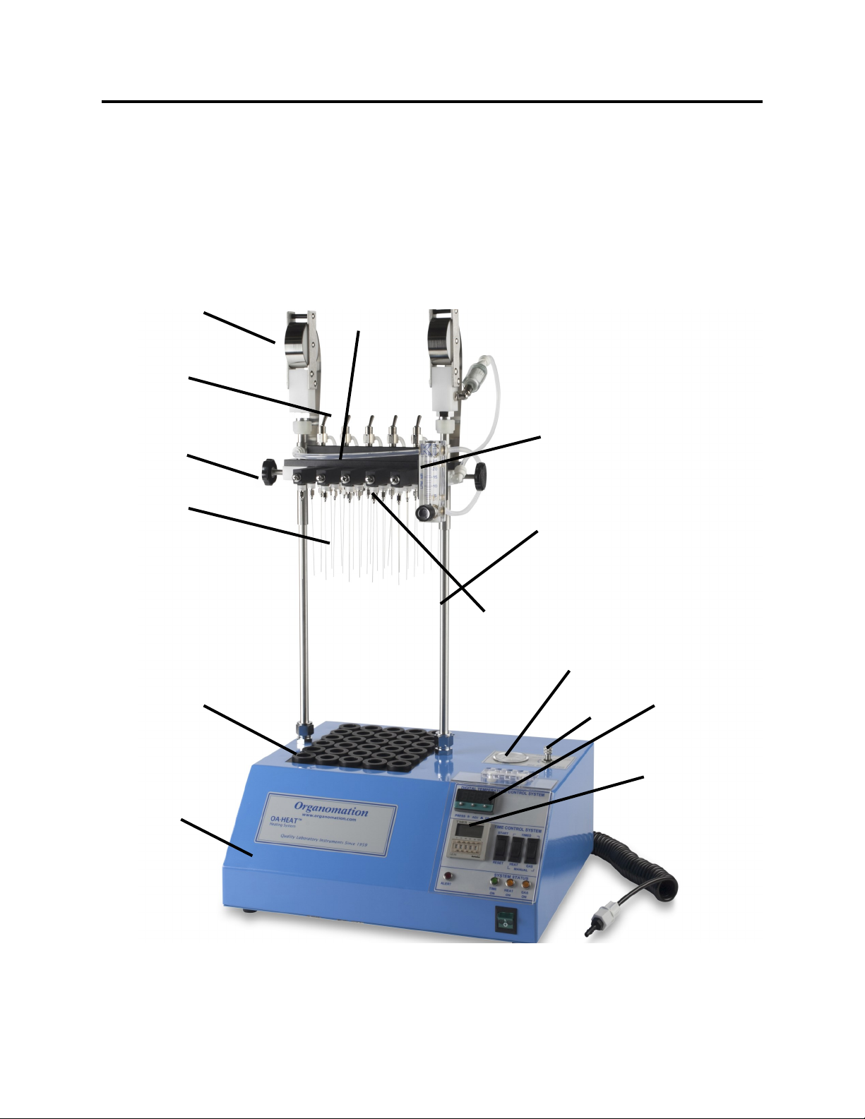
Your shipment should contain one or more of the instruments shown below. Option codes are
listed on the next page.
Instrument Size
9 Position MULTIVAP Nitrogen evaporation system
30 Position MULTIVAP Nitrogen evaporation system
48 Position MULTIVAP Nitrogen evaporation system
80 Position MULTIVAP Nitrogen evaporation system
Flow meter Assembly with Mounting Bracket & Connector Tube
0-30 or 0-100 LPM for all Model 118 MULTIVAP.
1 ea 11809, 11830 & 11848, & 11880
19 ga. x 4” Stainless Steel Needles, blunt end. 9, 30, 48, 80 each for respective
models and positions.
14 ga x 4” Stainless Steel Needles, blunt end. 18 ea for the 11809
Manual for MULTIVAP models 11809-80
Pasteur Pippet Adapter with flow controller, 1 Dozen per set (Optional).
Aluminum Inserts for 11809, size per order. Each
Aluminum Inserts, size per order. Set of 30.
Aluminum Inserts, size per order. Set of 48.
Aluminum Inserts, size per order. Set of 80
Cat #
11809
11830
11848
11880
NA1421
NA0603
NA1105-14
V10124
NA0636
NA1891
NA1832
NA1803
NA1882
MULTIVAP is a Trademark of Organomation

V15.1 - 5 -
INTRODUCTIONMULTIVAP 118
Option Codes and additional items shipped
The following list contains option codes and items which may have been shipped in
conjunction with the standard parts shown on the previous page. Please check your packing
list and order information carefully to determine if these items are included in your shipment.
Your shipment may contain the following optional items:
Description
Pasteur Pipit Fittings replace SS needles on the MULTIVAP. Provided
with the respective MULTIVAP size ordered, reference part # NA0637.
MULTIVAP Instrument and OA-HEAT heating unit are coated in PTFE.
Instrument is black in color. The water bath exterior is blue and the heat
block is black.
SS Needles 19 gauge x 4” (100mm) Long, are coated in PTFE and are
black in color.
OA-HEAT heating unit has been modified for the Type-Z Purge
Intrinsically Safe bath option. Additional parts include: differential
pressure gauge, mounting bracket, and tubing.
OA-HEAT water bath is wired as a 240 Volt unit.
Option
-P
-RT
-T
-Z
-2

V15.1 - 6 -
INTRODUCTIONMULTIVAP 118
Instrument Description
The MULTIVAP Nitrogen Evaporation System is designed for general evaporation
and / or concentration of analytical or biological samples in test tube based glassware under
controlled and reproducible conditions.
The complete instrument is shown below.
Figure 1
1
2
3
4
5
6
7
8
9
10
11
12
13
14

V15.1 - 7 -
INTRODUCTIONMULTIVAP 118
Item
(1)
(2)
(3)
(4)
(5)
(6)
(7)
(8)
(9)
(10)
(11)
(12)
(13)
(14)
Part Name
Hoist Assembly
Toggle Gas Valve
Lift Knob
Blunt Needle
PTFE coated
(Optional)
Insert
Heat Unit
Manifold
Flow Meter & Bracket
Gas Tube
Luer Fitting
Pressure Gauge
Pressure Regulator
Digital Controller
Timer Control
Description
Assists lifting of instrument. Delivers gas to
manifold.
On/Off gas control for each manifold row.
Rotate to raise and lower manifold.
Delivers gas to each sample.
PTFE coated for acid resistance.
Allows different diameter sample tubes in heat
block.
Dry block and control system.
Gas delivery system
Measures gas flow rate.
SS tube connects flow meter to manifold.
Connects SS needle to manifold.
Measures pressure.
Adjusts incoming pressure to system.
Temperature control system.
Time control system.
Cat #
P1224-M
P1303
P0612-N
NA0603
NA0603-T
see p.4
N A
N A
NA1421
N A
P1302
P0607
N A
N A
N A
N A
PARTS LIST

V15.1 - 8 -
INSTALLATIONMULTIVAP 118
Location
The MULTIVAP Evaporator System should be located on a bench top or in a chemical
fume hood if hazardous or flammable materials and solvents are to be used. The location
should provide the necessary support services for the instrument. These include electrical
power (required for dry block) and a clean inert gas source (Air or Nitrogen). Please review
the Specifications Section for further information.
Dry Bath Setup
1. Position the bath on a stable flat surface such as a lab bench or in a chemical fume
hood.
2. Turn the bath rocker switch to the “OFF” position.
3. Turn the heat switch to the center “OFF” position.
4. Plug the bath electrical cord into a 3 wire grounded electrical outlet rated for 110-120
VAC, 50-60 Hz, single phase, 15 amps.
Optional 220 VAC baths are clearly marked and should be plugged into a 3 wire
grounded electrical outlet rated for 220-240 VAC, 50-60 Hz, single phase, 15 amps.

V15.1 - 9 -
INSTALLATIONMULTIVAP 118
Dry Bath Setup (Continued)
6. Type-Z Purge Intrinsically Safe Bath option - If you do not have this option,
please proceed to the next section. Procedures for operating this system may be
found in the Operation Section. Quick start instructions are posted on the front of the bath.
Please refer to Figure 3 below for parts list and installation.
A. Install the Type Z Purge Gauge Assembly to the rear of the bath as shown. The
bracket attaches to the rear of the bath and is held in place by a 6-32 x 1/4” screw
on the shoulder spacer and by a 1/4” bulkhead hex nut on the gas inlet fitting.
B. Connect the small white silicone tube attached to the gauge to the gas inlet fitting
using the compression nut provided.
C. Attach the filter with 5 foot tube to the plastic elbow fitting located at the base of
the bath. Insert the filter into the fitting and tighten the nut. Connect the tube to
a clean gas source.
D. Test the system by turning on the gas flow to the Z Purge System. Adjust the
gas flow until the gauge reads 0.1 inches water pressure.
WARNING - If this unit is located in a hazardous area where volatile fumes are present,
the Z-Purge System must be activated for a minimum of 10 minutes prior
to activation of bath power. Please review the Safety and Operations
sections.
FIGURE 3
1
2
3
4
5
6
7
8
11
12
Gauge and Housing
1/4 White Silicone Tube
10/32 x 1/4 Screw
Tube Fitting Nut
3/8 OD Clear Tube
Bulkhead Hex Nut
Filter
Plastic Elbow Fitting
Shoulder Spacer
Gas Inlet Fitting
Front
Z-Purge Assembly Diagram - Side View

V15.1 - 10 -
INSTALLATIONMULTIVAP 118
Dry Bath Setup (Continued)
8. Connect the black connector tube to the lower left connector on the rear of the unit
labeled GAS INPUT. Connect the other end to a suitable gas source.
9. Pressure Control is standard on all MULTIVAPs. This item is pre-installed onto the
top of the bath box. Adjustment range is 0 - 30 psig.
10. Fill the bath with water to within one inch of the rim, approximately (25mm). To
reduce scale and mineral buildup, de-ionized or distilled water may be used.

V15.1 - 11 -
INSTALLATIONMULTIVAP 118
Instrument Setup
1. Install the two 5/8” DIA SS Tubes into the fittings located on either side of the
bath chamber. Tighten the compression screws.
2. Place the manifold over the tops of the two 5/8” SS tubes and slide the manifold
downwards until 2 inches (50mm) of the tube extend above the manifold. Lock
the manifold in place by tightening the thumb screws on each side.
3. Flow Meter Assembly for MULTIVAP Systems purchased with a side mounted control
box.
A. The flow meter will be attached to the top right bracket of the manifold assem-
bly. The meter should be positioned with the needle valve facing forward.
B. The right post is the gas source; it flows into the right hand hoist assembly
and into the flow meter.
4. Connect the coiled black connector tube to the fitting located on the lower back right
corner of the control box. Press firmly into place.
5. Install the aluminum test tube inserts into the heating unit. Inserts are available for a
wide range of test tube diameters and may be used interchangeably as needed. When
properly installed, the insert will rest in the bottom of the hole.

V15.1 - 12 -
INSTALLATIONMULTIVAP 118
Instrument Setup (Continued)
7. Needles and Pipets - SS Luer Lock Needles are supplied with the standard MULTIVAP
system. Optional Pasteur Pipet Adapters allow the use of glass pipets. These fittings
replace SS Needles on the MULTIVAP. Pasteur Pipet Adapters may be purchased
separately with the standard MULTIVAP, allowing the use of both needles and pipets.
A. SS Needles - Install into the Luer fittings at the bottom of the manifold
assembly by rotating the needle 1/2 turn. Do not over tighten, finger tight only.
It is recommended that the needles be installed from the back forward.
B. Pasteur Pipet Adapters - Carefully push the pipet onto the Pasteur pipet
adapter. Install the pipet/PPA assembly into the Luer fitting at the bottom of the
manifold assembly by rotating 1/2 turn. 15cm glass pipets are recommended.
Needles or PPA’s may be used interchangeably in the MULTIVAP at the same
time.
Note: It is recommended that the needle guide plate be removed when using
pipets.
8. Install the inserts into the heating unit.
9. Align the manifold so that the needle tips are centered over the test tube holes in the
block.

V15.1 - 13 -
SAFETYMULTIVAP 118
Safety Considerations
READ THIS SECTION BEFORE EQUIPMENT OPERATION!
This equipment is designed for use in the Analytical or Environmental Laboratory by trained
laboratory personnel for evaporative applications. Use of this equipment beyond its stated
intended purpose and operating parameters is not recommended and will be the sole
responsibility of the user. This equipment should not be modified or altered. Organomation
assumes no liability for any misuse of or modification to this product and such misuse or
modification will immediately void all warranties.
This equipment should be used in accordance with the operating instructions contained in this
manual. For alternative uses not covered in this manual, please contact Organomation
technical department for product suitability, safety, and alternative operating instructions.
The following are general safety guidelines recommended when using this product. Please
consult your laboratory safety officer for any additional safety steps which may be necessary
for your specific application or material.
1. Thoroughly review your MSDS (Material Safety Data Sheets) for all chemicals to be
used with this equipment.
2. Do not use this equipment with materials with auto ignition points below 150 ºC.
3. Hand and eye protection are required when using this product. Additional protection
may be required with respect to the materials being used. Please consult your labora-
tory safety officer.
4. This product should be used in a chemical fume hood with adequate ventilation.
5. Do not move the product when hot.
6. Do not open bath enclosure while energized - SHOCK HAZARD!
7. Repairs of electrical components should be conducted by a trained electrical technician.
Incorrect replacement parts or assembly may damage the product and create a serious
safety hazard for the user. Factory repair is highly recommended.
8. Highly flammable materials such as Petroleum Ether should not be used with this
product unless the Type-Z Purge intrinsically safe bath option is installed and
operating.
9. Use of acidic or base materials may damage this product and are not recommended
unless the product was ordered with the optional protective coating in PTFE.

V15.1 - 14 -
OPERATIONMULTIVAP 118
Instrument Controls - Main Control Panel
Digital Controller - Controls bath temperature
Timer Controller - Controls timed functions when selected. Used for bath preheat
or automated control of services.
Time Switch - Starts or resets timed operation, momentary switch.
Heat Switch - Selects manual or timed control of heat system.
Gas Switch - Selects manual or timed control of gas system.
Time Light - Green, indicates timed operation in progress.
Alert Light - Red, indicates timed operation complete or inactive.
Heat Light - Amber, indicates heat system is active.
Gas Light - Amber, indicates gas system is active.
ON / OFF Switch
Green Lighted Rocker
ALERT Indicator
Red Light
TIME System ON
Green Light
HEAT System ON
Amber Light
GAS System ON
Amber Light
HEAT Switch
ON / OFF / ON
GAS Switch
ON / OFF / ON
Manual Control
Timed Control
TIME Controller
Digital Temperature
Controller
Function Button
Adjustment Buttons
Program Choice Wheel
Time Setting Wheels
Time Increment Wheel
TIME Switch
Start / Null / Reset

V15.1 - 15 -
OPERATIONMULTIVAP 118
Type Z-Purge Bath Operation - Optional
What It Does
The Type-Z Purged system prevents ignition of flammable materials caused by contact with
electrical components inside the heating unit.
How It Works
The concept behind this purge system is to create a small positive pressure gradient inside the
bath case. By carefully sealing the heating unit or control enclosure, a small flow of clean air
or inert gas will create a slight positive pressure within the enclosure. It is important to note
that there is constant leakage out of the enclosure. In this way the enclosure is continually
purged. The pressure gradient prevents flammable vapors and occasional spills from entering
the enclosure where arcing components or high surface temperature heaters might cause
ignition. The use of an inert gas such as nitrogen enhances the technique by removing all oxy-
gen from the enclosure. By purging the enclosure for 10 minutes, the gas volume within the
enclosure is replaced multiple times ensuring that no flammable vapors remain which may have
entered while the purge system was inactive.
Operating Procedure
1. Turn on the gas flow to the Z-Purge System. Purge gas may be clean air or inert gas
such as Nitrogen. The use of Nitrogen is recommended.
2. Adjust the gas flow until 0.5 inches water pressure is maintained on the gauge
mounted on the heating unit.
3. Purge the bath for 10 minutes before engaging the electrical system.
4. After 10 minutes the gas flow may be adjusted to 0.1
5. Turn on the electrical heating unit. The purge rate must be maintained.
6. Proceed to the next section.

V15.1 - 16 -
SAFETYMULTIVAP 118
Planning and Preparation
It is important to thoroughly understand the procedures and equipment operation prior to
the use of the equipment. High speed nitrogen evaporation requires a balance of sample
volume, nitrogen flow, bath temperature, needle position and adjustment. Improper use can
impair performance, contaminate samples or result in loss of samples. Environmental
conditions are also important, examples include hood airborne contaminates, gas purge purity,
and sample handling procedures. If you are unfamiliar with the use of the MULTIVAP System
or are working with a new procedure, it is recommended that a trial run be made using a sample
blank to determine optimal operating conditions.
The MULTIVAP System is designed to handle multiple samples simultaneously up to the
capacity of the equipment. Glass or plastic tubes from 10 to 30mm OD and up to 150mm
height may be accommodated. Centrifuge tubes, scintillation vials, and small beakers may also
be used. Choice of SS needles or disposable glass pipets (fittings) are available.
The MULTIVAP System is manufactured utilizing inert materials. FDA approved Phthalate
free tubing is used on the manifold. The black connector tube is polyurethane and internal
tubing is polyethylene, both of which are Phthalate free.
CAUTION!!!
Samples containing ether based, fuel, munitions, or other extremely flammable or
explosive materials, compounds, or residues should not be used in this equipment unless
the heating unit is equipped with the TYPE -Z Purged Intrinsically Safe Bath Option.
Even equipped with this option, extreme care and caution must be exercised when using these
materials. The equipment must be placed in a location with adequate ventilation and safe
guards, recommendations include fire suppression system, shatter proof glass, and adequate
shielding for personnel. No other electronic devices should in the same location unless they are
either Z-Purge protected or are explosion proof. No flammable solvents should be stored in this
location. Materials capable of forming peroxides prior to or during evaporation must be
stabilized with sufficient anti-oxidant or they should not be used.
Under no circumstances should this equipment be used with materials capable of auto
ignition below 150 Degrees Centigrade including materials containing peroxides.
Please Contact Organomation Associates Technical Support if you have any questions
concerning the use of TYPE-Z Purged equipment or questionable materials in OAI
equipment.

V15.1 - 17 -
OPERATIONMULTIVAP 118
Bath Operation
1. Press the reset button on the GFCI (if present).
2. Turn the bath rocker switch on.
3. Digital Electronic Control - Adjust the digital controller to the desired temperature
set point.
The controller set point may be adjusted by depressing the “*” on the front panel and
depressing the up or down arrow keys to the desired temperature. Release the “*” key
when the temperature desired is shown on the display. This setting will be retained
even after the system is turned off.
To view the current set point, depress and hold the “*” key. Release when done.
4. Manual Gas and Heat Control
A) To operate the heat system manually, depress the heat switch to the lower
position. The Amber heat light will glow indicating the heat system is active.
Temperature will be controlled by the digital temperature controller.
B) To operate the gas system manually, depress the gas switch to the lower position.
The Amber gas light will glow indicating the gas system is active. The gas
system is controlled by a solenoid valve located within the control box. When
active the solenoid is open allowing gas flow to the flow meter and subsequently
to the needle valves on the instrument.
C) To turn off either service, simply return the switches to the middle “OFF”
position.

V15.1 - 18 -
OPERATIONMULTIVAP 118
Bath Operation
5. Timed Gas and Heat Control
The Time control system allows several operating modes which can be set for different
operations. The timer may be used to preheat the bath in the morning prior to use, to
shut down the system after a specific period of time (unattended operation), or for non-
dryness endpoint operations.
Preheat Bath Timed Operation
To begin heating the bath automatically prior to use the following morning, please
follow the procedures below.
A) Turn the bath off.
B) Set the left hand timer dial to program “C”. Program C is DELAY / OPERATE
time function.
C) Set the right hand dial to 0.1H. This will allow time settings to tenths. The
three center dials may be set to the correct number of hours with the right hand
most dial representing 0.1 hours. Calculate the amount of time that will elapse
from the point the bath will be left until it will be needed the following day less 1
hour for heat up time.
Example: You leave at 5:30 PM and plan to arrive at 7:00 AM and want the
bath heated and ready to go.
Elapsed time is 13.5 hours less 1 hour for heating leaves 12.5
hours. Set the timer as follows:
0.1
C 1 2 5 H
D) Set the heat switch to timed operation
E) Set the gas switch to the middle position (OFF).
F) Turn the main power switch on.
G) Press the start switch to begin the timed countdown operation. At the
completion of the operation the bath heat will be turned on automatically.

V15.1 - 19 -
OPERATIONMULTIVAP 118
Bath Operation (continued)
5. Timed Gas and Heat Control (Continued)
Automatic shutdown of gas or heat services - unattended operation
To shut down the bath services after a period of time during a sample evaporative run,
ideal when each sample is to be taken to dryness and the operator will not be present at
the completion of the run. Please follow the procedures below.
A) Set the left hand timer dial to program “H”. Program H is an OPERATE /
STOP time function.
B) Set the right hand dial to the time increment (seconds, minutes, hours, or tenths
of same) which is most ideal for the period necessary to process the sample.
The three center dials may be set to the correct amount of time to complete the
run. As most samples will vary slightly in their evaporative times to dryness an
addition period of time should be allowed prior to shutdown. Ten to twenty
minutes should be adequate.
Example: You wish to process 18 samples in 16 x 100mm test tubes to
dryness. Experience has shown that this takes approximately 25
minutes to complete. As you are expected in a meeting which
may take an hour or more, you should use the automatic time
system as there is no need to waste unnecessary gas flow:
Evaporation time is 25 minutes plus 10 minutes for variance, this
gives 35 minutes. Set the timer as follows:
H 0 3 5 M
C) Set the heat switch to timed operation or manual to bypass timed control.
D) Set the gas switch to the timed position.
E) Follow instrument instruction procedures for flow meter and needle valve
settings.
F) Press the start switch to begin the timed countdown operation. At the
completion of the operation the gas flow will be turned off automatically.
NOTE: To stop a timed run at any point simply push the reset switch.

V15.1 - 20 -
OPERATIONMULTIVAP 118
Bath Operation (continued)
5. Timed Gas and Heat Control (Continued)
Non-dryness automated endpoint - unattended operation
The MULTIVAP system may be used for timed non-dryness endpoint evaporation. In
order for this operation to be successful the following parameters must be maintained.
Test Tube Size - All tubes must be the same size
Sample Volume - All sample volumes must be equal
Gas Flow Rate - Must be the same per sample / per position / per run
Bath temperature - The same set point must be used for each run
A trial run must be made to determine the time required to obtain the specific endpoint
desired. Careful notes should be maintained on all operating conditions. Sample size,
volume, and gas flow are the most critical, with gas flow being the most difficult to
control. Please follow the procedures outlined in the previous section for operation of
the timed system with unattended operation and shut down.
The following procedures will help to improve accuracy for each run.
A) Set the pressure regulator to a position high enough to meet all flow require-
ments 20 - 30 PSIG should be sufficient for most applications.
B) Open each row with toggle switch
C) Gas flow to each position should be increased to 0.5 LPM / Position.
D) Samples should be equally distributed around the bath.
E) Maintain a log of all operating conditions and positions for future use.
Experimentation has demonstrated that evaporation rate at a given temperature range is largely a
function of gas flow rate, 92%. Minor fluctuation in temperature +/- 2 degrees Celsius have
little impact on rate, less than 8%. At endpoint, evaporative losses by heat alone are negligible
for short periods of time, 10 - 30 minutes, except for very volatile compounds.
This manual suits for next models
3
Table of contents
Other Organomation Laboratory Equipment manuals
Popular Laboratory Equipment manuals by other brands

J.P. SELECTA
J.P. SELECTA HPC PL-3 manual

PerkinElmer
PerkinElmer VICTOR Nivo user manual

PerkinElmer
PerkinElmer Panthera-Puncher 9 Instrument manual

Isotech
Isotech LIBRA 785 User maintenance manual/handbook

Home Science Tools
Home Science Tools CE-HOTSTIR manual

B. Braun
B. Braun Perfusor Space Instructions for use

Thermo Scientific
Thermo Scientific F6000 Installation and operation manual

Keysight
Keysight E8257D Option H1K Installation notes

XD COLLECTION
XD COLLECTION P301.11 Series manual

Upvel
Upvel UP-105GI Quick installation guide

Thermo Scientific
Thermo Scientific Nicolet Summit user guide

Dreve
Dreve PCU LED N2 Instructions for use