manuals.online logo
Brands
  1. Home
  2. •
  3. Brands
  4. •
  5. IKA
  6. •
  7. Laboratory Equipment
  8. •
  9. IKA RW 16 basic User manual

IKA RW 16 basic User manual

B
ETRIEBSANLEITUNG
D
5
O
PERATING INSTRUCTIONS
GB
10
M
ODE D
’
EMPLOI
F
15
I
NSTRUCCIONES DE MANEJO
E
20
H
ANDLEIDING
NL
25
I
NSTRUZIONI PER L
’
USO
I
30
D
RIFTSANVISNING
S
35
D
RIFTSINSTRUKS
DK
40
K
ÄYTTÖOHJE
N
45
D
RIFTSVEJLEDNING
SF
50
Ο∆ΗΓΙΕΣ ΛΕΙΤΟΥΡΓΙΑΣ
GR
55
I
NSTRU
ÇÕ
ES DE SERVI
Ç
O
P
60
IKA®WERKE
RW160995EU
Reg.-No. 4343-01
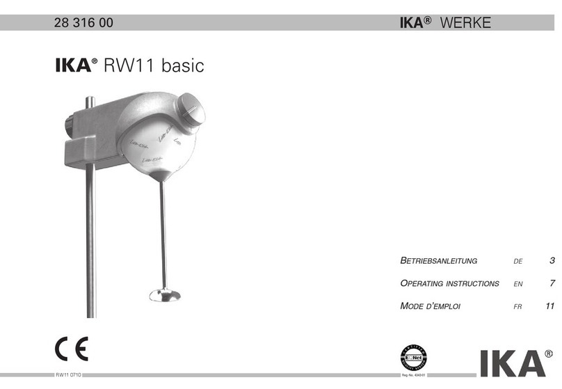
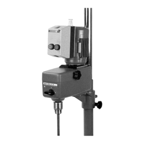
IKA RW 16 basic
25 510 00
RW160995EU 12.11.2001 13:39 Uhr Seite 1
Page
Safety instructions 10
Correct use 11
Unpacking 11
Useful details 11
Drive 11
Motor protection, safety devices 11
Speed 12
Commissioning 12
Mounting extension arm 12
Switching apparatus on 12
Output shaft 13
Maintenance and cleaning 13
Accessories 13
Technical data 13
Permitted IKA stirrer tools 14
Associated standards and regulations 14
Guarantee 14
Spare parts list 66
Spare parts diagram 67
Never operate the equipment with the stirrer tools rotating
freely. Ensure that parts of the body, hair or items of clothing
cannot be trapped by the rotating parts. Pay attention when
setting the speed to any imbalance of the stirrer tools and
possible spraying of the medium to be stirred. Use a stirrer shaft
protection device!
The equipment is not suitable for manual operation. Please follow
the relevant safety instructions and guidelines, and occupational
health and safety regulations for use in the laboratory.
Avoid knocks and impacts on the lower end of the shaft and the
chuck gear teeth. Even minor, invisible damage can lead to im-
balance and uneven shaft action. Careful handling guarantees
safe working and the long life of the equipment.
Imbalance of the output shaft, the chuck and in particular the
stirring tools can lead to uncontrolled resonant vibrational
behaviour of the equipment and the whole assembly. Glass
apparatus and stirrer containers can be damaged or shattered by
this. It can cause injury to the operator, as can the rotating stirring
tool. If vibration of the equipment is noticed, the speed must be
reduced immediately in all cases until no more vibration occurs.
In this case exchange the stirring tool for one without imbalance
or remedy the cause of the imbalance.
Operating with a freely rotating shaft end is dangerous. Therefore
for safety reasons the stirrer tool is permitted to project over the
upper edge of the housing only when the machine is not running.
For correct operation, the rubber diaphragm must always be com-
pletely closed. Take care to ensure that the shaft never runs
directly in the rubber diaphragm and any friction with rotating
parts (stirrer shafts) is excluded.
The machine may only be opened by trained specialists - even
during repairs. The machine is to be unplugged from the mains
before opening. Live parts inside the machine may still be live for
some time after unplugging from the mains.
10 RW160995EU
CONTENTS
Safety instructions
RW160995EU 12.11.2001 13:39 Uhr Seite 10
The basic RW 16 stirrer is suitable for stirring and mixing fluids
with low viscosity. It is designed for use in laboratories. For
correct use, the equipment must be secured to a fixed object.
Please unpack the machine carefully and inspect for damage. It is
important that any transit damage should be noted at the time of
unpacking. In certain circumstances it may be necessary to in-
vestigate immediately (post, rail or freight forwarder). The guaran-
tee covers: One RW 16 stirring machine, one extension arm, one
hexagonal socket screw, one hexagon socket offset screw key
and operating instructions.
In buying this machine you have chosen a high quality product.
Ease of use is guaranteed with its handy shape and simple ope-
ration. The housing offers protection against ingress of liquids.
The materials used and their precise identification make recycling
possible and simple, and enables re-use of the parts. The
generously proportioned cooling surfaces enable distribution and
transference of heat to be as even as possible. The two metre
long mains lead makes it possible to work on stands - even with
high glass apparatus under vapour extraction hoods - without
extension leads. The precision stirrer shaft is designed as a hol-
low shaft to allow the stirrer shanks to be inserted.
The speed of the RW 16 basic stirrers can be infinitely adjusted
by electronic means. The ball bearing equipped DC motor has a
quiet synchronous belt drive. The motor is controlled via a com-
puter-controlled speed regulator using pulse-width modulated vol-
tage (PWM). The whole drive unit is maintenance-free.
The machine is suitable for continuous operation. The motor cur-
rent is electronically limited. The machine has an anti-stall and
anti-overload system. If a fault occurs, a safety circuit immediate-
ly switches off the motor permanently via a relay.
To start the machine again after a fault, please operate the mains
switch. If the machine still does not work, please contact our
Service department.
11
RW160995EU
Unpacking
Drive
Useful facts
Motor protection; safety devices
Correct use
RW160995EU 12.11.2001 13:39 Uhr Seite 11
The speed is set using the front knob(A). The scale from 1 to 10
corresponds to a speed range for the output shaft of 40 to 1200
rpm under nominal load. With no load the speed at maximum set-
ting of the knob (right position) is 1600 rpm, at minimum setting
of the knob (left position) 0 rpm. If viscosity increases due to the
process, the speed reduces gradually. If, however, the viscosity is
reduced by eg the addition of thinning agents, the speed increa-
ses somewhat. This can be balanced out in both cases by re-set-
ting the knob accordingly, provided torque does not exceed maxi-
mum torque. Please note that fluctuations in mains voltage wit-
hin the permitted tolerances may also cause minor fluctuations in
speed.
For correct use, the stirrer must be secured to a stable object
(eg R1822) with a cross-sleeve (eg R181). For safety reasons the
stirrer container should always be fixed with a tension-holder
(eg RH1).
For diagram see (Fig. 2)
The extension arm (X) has a step at its end with a cross hole. This
end is used to insert the extension arm into the hole on the back
of the machine. To do this, the cross hole in the extension arm
must point upwards. It must be brought into alignment with the
hole in the fixing rib on the back of the machine. To do this, press
the extension arm until it catches in the hole. Please do not use
force to do this. If it proves difficult to insert the extension arm,
light oiling may help. The hexagonal socket screw (Y) used for
fixing is inserted in the hole in the housing from above. The screw
is tightened using the hexagon socket offset screw key (Z).
Check that the extension arm is firmly seated. The screw may
loosen with vibration. Therefore as a precaution check from time
to time that the extension arm is still securely attached.
If necessary tighten the hexagonal socket screw.
You can also secure the hexagonal socket screw with adhesive,
but you are then unable to release the connection later
.
Check whether the voltage given on the type plate corresponds
to the available mains voltage. The socket used must be earthed
(fitted with earth contact). If these conditions have been met, the
machine is ready to operate when the mains plug is plugged in.
If these conditions are not met, safe operation is not guaranteed
and the machine could be damaged.
The machine is started by pressing the mains switch (B) into
position “l”. A green control light (C) signals the operating
condition “ON”.
During commissioning of the machine the output shaft starts to
run at the last speed set. Therefore check the setting of the con-
trol knob. Also ensure that the speed set is suitable for the test
texture selected. If in doubt, set the speed knob (A) to the lowest
speed (left-hand position).
12 RW160995EU
Commissioning
Mounting the extension arm
Speed
Switching on the machine
RW160995EU 12.11.2001 13:39 Uhr Seite 12

The clamping chuck and output shaft permit all standard
commercial stirrer tools up to 10mm diameter to be gripped and
screwed in. The opening on the top side of the housing is closed
with a slotted rubber diaphragm. It is, however, possible for stir-
ring shafts to push out over the top edge of the housing eg during
change of container.
If it becomes necessary - depending on the layout of the equip-
ment - to allow the shaft end to project over the edge of the hou-
sing during operations, the rubber diaphragm should be removed.
Instead a stirrer shaft cover, which can be obtained as an acc-
essory, must be placed on the housing. If the stirrer shaft cover
is removed again, the rubber diaphragm must be pressed into the
housing opening again so that this is closed. This is the only way
of ensuring safe working and preventing any fluids from penetra-
ting the equipment.
Please see section ”Safety Instructions”!
The stirrer is maintenance-free. It is subject only to the natural
wear and tear of components and their statistical failure rate.
When ordering spare parts, please give the manufacturing
number shown on the type plate, the machine type and the
name of the spare part.
Please send in equipment for repair only after it has been clea-
ned and is free from any materials which may constitute a
health hazard. Only use water with a detergent additive contai-
ning a surfactant for cleaning, or for heavier soiling isopropylal-
cohol.
R 1822
Fixed plate
RH 1
Tension-holder
R 181
Cross-sleeve
FK 1
Flexible connection
DZM 1
Speedometer; RLS 8 x 33
Speed range under nominal load: min
-1 40-1200
Max. stirrer speed:
Ncm 40
Permitted switched-on time: %100
Speed setting:
Speed adjuster with pulse width modulator
Speed indicator: Scale on knob
Nominal voltage:
VAC
230±10%
EURO
VAC
115±10%
USA
Frequency: Hz 50 / 60
Input power: W75
Output power: W55
Output on stirrer shaft: W53
Total efficiency: 0,71
Protection type to DIN 40 050: IP42
Excess voltage category: II
Degree of pollution: 2
Overload protection: El. current limitation
Fuses (on mains plate): A4 T (IKA ident.no. 25 851 00)
13
RW160995EU
Output shaft
Maintenance and cleaning
Accessories
Technical data
Protection measures:
0
Class Protection device Recommended use
0
No additional protection
Used only on equipment where
failure of the controls does
not represent a hazard.
The operating conditions should be monitored at regular intervals.
RW160995EU 12.11.2001 13:39 Uhr Seite 13
A Drive
(maintenance-free)
: DC motor with 1-level synchronous belt drive
Environmental temp.: °C +5 to+40
Environmental humidity: %80
Operating position:
on fixed object, tension filler facing down
Max. qty. of stirred water: ltr 10
for viscosity: LV
Clamping chuck tension range: mm 0,5 -10
Hollow shaft, internal dia.: mm 11
Extension: mm 13x160long
Housing: Al diecast, thermoplast. plastic
Dimensions excl. extension: mm (BxTxH)
80x190x175
Weight with extension and
clamping chuck: kg 2,8
Speed deviations:
Adjustment precision: %10
When loaded: %0 load nmax= 1600 min-1 (nom.)
%100 load nmax= 1200 min-1 (nom.)
Max. speed rpm
R1342 Propeller stirrer 4fl 2 000
R1381 Propeller stirrer 3fl 2 000
R1382 Propeller stirrer 3fl 2 000
R1389 Propeller stirrer 3fl PTFE 800
R1352 Centrifugal stirrer 2 000
R1311 Turbine stirrer 2 000
R1312 Turbine stirrer 2 000
R1335 Kneading stirrer 2 000
R1330 Anchor stirrer PTFE 1 000
Associated EU guidelines
EMV guidelines: 89/336/EC
Machine guidelines: 89/392/EC
Construction in accordance with the following safety standards:
EN 61 010-1 /VDE 411-1 EN 292-1, -2
EN 50 082-1 EN 414
EN 55 014-1 IEC 1010-1
EN 60 555-2, -3 UL 3101-1
EN 60 204-1 CAN/CSA C22.2 (1010-1)
You have purchased an original IKA laboratory machine which
meets the highest engineering and quality standards.
In accordance with IKA guarantee conditions, the guarantee peri-
od is 12 months. For claims under the guarantee please contact
your local dealer. You may also send the machine direct to our
works, enclosing the delivery invoice and giving reasons for the
claim. You will be liable for freight costs.
14 RW160995EU
Viscosity
mPa · s
VLV very low viscosity 0 .......... 100
water up to
thin-flowing oil
LV low viscosity 100....... 1000
thin-flowing oil up to
thick-flowing oil
MV medium viscosity 1000.. 10000
thick-flowing oil up to
honey at approx. 20 °C.
HV high viscosity 10000 100000 honey at approx. 20 °C
up to printing inks
Permitted IKA stirrer tools
Associated standards and regulation
s
Guarantee
RW160995EU 12.11.2001 13:40 Uhr Seite 14

Other manuals for RW 16 basic

5

Other IKA Laboratory Equipment manuals

IKA I-MAG 300 User manual

IKA

IKA I-MAG 300 User manual

IKA ULTRA-TURRAX T 50 basic User manual

IKA

IKA ULTRA-TURRAX T 50 basic User manual

IKA ULTRA-TURRAX T 50 basic User manual

IKA

IKA ULTRA-TURRAX T 50 basic User manual

IKA A 11 basic User manual

IKA

IKA A 11 basic User manual

IKA IKAMAG KMO 2 basic User manual

IKA

IKA IKAMAG KMO 2 basic User manual

IKA RW 47 digital User manual

IKA

IKA RW 47 digital User manual

IKA Roller 6 basic User manual

IKA

IKA Roller 6 basic User manual

IKA Roller 6 basic User manual

IKA

IKA Roller 6 basic User manual

IKA C-MAG HS4 User manual

IKA

IKA C-MAG HS4 User manual

IKA MS 1 User manual

IKA

IKA MS 1 User manual

IKA MIDI MR 1 digital User manual

IKA

IKA MIDI MR 1 digital User manual

IKA A10 basic User manual

IKA

IKA A10 basic User manual

IKA ULTRA -TURRAX Tube Drive User manual

IKA

IKA ULTRA -TURRAX Tube Drive User manual

IKA RW 16 basic User manual

IKA

IKA RW 16 basic User manual

IKA RV 10 control User manual

IKA

IKA RV 10 control User manual

IKA RW 47 D User manual

IKA

IKA RW 47 D User manual

IKA RW 16 basic User manual

IKA

IKA RW 16 basic User manual

IKA IKA C 248 User manual

IKA

IKA IKA C 248 User manual

IKA HS/KS 260 basic User manual

IKA

IKA HS/KS 260 basic User manual

IKA IKAMAG RET basic User manual

IKA

IKA IKAMAG RET basic User manual

IKA EUROSTAR digital User manual

IKA

IKA EUROSTAR digital User manual

IKA RV 3 eco User manual

IKA

IKA RV 3 eco User manual

IKA LR-2.ST User manual

IKA

IKA LR-2.ST User manual

IKA LR 1000 basic User manual

IKA

IKA LR 1000 basic User manual

Popular Laboratory Equipment manuals by other brands

Quanser IP01 user manual

Quanser

Quanser IP01 user manual

Grant Optima T100 operating manual

Grant

Grant Optima T100 operating manual

DLab Liquid Handling HiPette user manual

DLab

DLab Liquid Handling HiPette user manual

Bruker DektakXT user manual

Bruker

Bruker DektakXT user manual

Biobase BSC-2FA2-HA user manual

Biobase

Biobase BSC-2FA2-HA user manual

Visionix optovue ifusion80 user manual

Visionix

Visionix optovue ifusion80 user manual

MingTai SUN8-II Operation manual

MingTai

MingTai SUN8-II Operation manual

CEM EasyPrep Series manual

CEM

CEM EasyPrep Series manual

Huvitz Excelon CAB-4000 Operator's manual

Huvitz

Huvitz Excelon CAB-4000 Operator's manual

Steris VHP X10 Operator's manual

Steris

Steris VHP X10 Operator's manual

Sanuvox S300 VOC Installer's instructions

Sanuvox

Sanuvox S300 VOC Installer's instructions

Codonics Horizon Starter manual

Codonics

Codonics Horizon Starter manual

VERDER Carbolite Gero CR/180 Installation, operation and maintenance instructions

VERDER

VERDER Carbolite Gero CR/180 Installation, operation and maintenance instructions

socorex ACURA 841 operating instructions

socorex

socorex ACURA 841 operating instructions

VPixx Technologies VPX-ACC-5180 Assembly instructions

VPixx Technologies

VPixx Technologies VPX-ACC-5180 Assembly instructions

Sutter Instrument LAMBDA 10-B Operation manual

Sutter Instrument

Sutter Instrument LAMBDA 10-B Operation manual

BPC instruments BPC Blue Operation and maintenance manual

BPC instruments

BPC instruments BPC Blue Operation and maintenance manual

Analytic Jena contrAA 700 user manual

Analytic Jena

Analytic Jena contrAA 700 user manual

manuals.online logo
manuals.online logoBrands
  • About & Mission
  • Contact us
  • Privacy Policy
  • Terms and Conditions

Copyright 2025 Manuals.Online. All Rights Reserved.