iDirect X1 Series Installation instructions

Installation, Support, and
Maintenance Guide
X1 Series Satellite Router
Router Products
September 14, 2017
X1 Series Satellite Router Installation, Support, and Maintenance Guide

ii Installation, Support, and Maintenance Guide
X1 Series Satellite Router
Copyright © 2017. VT iDirect, Inc., 13861 Sunrise Valley Drive, Suite 300, Herndon, VA 20171, USA.
All rights reserved. Reproduction in whole or in part without permission is prohibited. Information contained herein
is subject to change without notice. The specifications and information regarding the products in this document are
subject to change without notice. All statements, information and recommendations in this document are believed
to be accurate, but are presented without warranty of any kind, express, or implied. Users must take full
responsibility for their application of any products. Trademarks, brand names and products mentioned in this
document are the property of their respective owners. All such references are used strictly in an editorial fashion
with no intent to convey any affiliation with the name or the product's rightful owner.
VT iDirect®is a global leader in IP-based satellite communications providing technology and solutions that enable
our partners worldwide to optimize their networks, differentiate their services and profitably expand their
businesses. Our product portfolio, branded under the name iDirect®, sets standards in performance and efficiency
to deliver voice, video and data connectivity anywhere in the world. VT iDirect®is the world’s largest TDMA
enterprise VSAT manufacturer and is the leader in key industries including mobility, military/government and
cellular backhaul.
Company Web site: www.idirect.net ~ Main Phone: 703.648.8000
iDirect Government™, created in 2007, is a wholly owned subsidiary of iDirect and was formed to better serve the
U.S. government and defense communities.
Company Web site: www.idirectgov.com ~ Main Phone: 703.648.8118
TAC Contact Information: Phone: 703.648.8111 ~ Email: tac@idirectgov.com ~ Web site: tac.idirectgov.com
Document Name: ISM_X1_T0000482_RevE_09142017.pdf
Document Part Number: T0000482

Installation, Support, and Maintenance Guide iii
X1 Series Satellite Router
Revision History
The following table shows all revisions for this document. Refer to this information to verify
the version of this document. To verify the latest version, access the TAC Web site at
http://tac.idirect.net.
Revision Date Released Reason for Change(s)
A June 30, 2013 Initial release
B July 07, 2016 Add option: X1 (indoor) 3; altitude 2000 m
C March 13, 2017 Updated Power Supply Unit Consumption in
Tabl e 2 - 2 .
D May 12, 2017 Updated Appendix D.
E September 14, 2017 Added a section on Installing Ferrite on the AC
to DC Power Cable in Chapter 5 and Removed
the X1 Indoor DC Power Supply option

iv Installation, Support, and Maintenance Guide
X1 Series Satellite Router
Revision History

Installation, Support, and Maintenance Guide v
X1 Series Satellite Router
Contents
About . . . . . . . . . . . . . . . . . . . . . . . . . . . . . . . . . . . . . . . . . . . . . . . . . . . . . . . xi
Intended Audience . . . . . . . . . . . . . . . . . . . . . . . . . . . . . . . . . . . . . . . . . . . . . xi
Manual Contents. . . . . . . . . . . . . . . . . . . . . . . . . . . . . . . . . . . . . . . . . . . . . . . xi
Document Conventions . . . . . . . . . . . . . . . . . . . . . . . . . . . . . . . . . . . . . . . . . . xii
Related Documents . . . . . . . . . . . . . . . . . . . . . . . . . . . . . . . . . . . . . . . . . . . . xiii
Related Training Services . . . . . . . . . . . . . . . . . . . . . . . . . . . . . . . . . . . . . . . xiii
Getting Help . . . . . . . . . . . . . . . . . . . . . . . . . . . . . . . . . . . . . . . . . . . . . . . . xiii
1 Introduction . . . . . . . . . . . . . . . . . . . . . . . . . . . . . . . . . . . . . . . . . . . . . . . . . 1
1.1 X1 Router . . . . . . . . . . . . . . . . . . . . . . . . . . . . . . . . . . . . . . . . . . . . . . . . . 1
1.2 X1 Outdoor Router . . . . . . . . . . . . . . . . . . . . . . . . . . . . . . . . . . . . . . . . . . . 2
2 Specifications. . . . . . . . . . . . . . . . . . . . . . . . . . . . . . . . . . . . . . . . . . . . . . . . 3
2.1 X1 Router Specifications . . . . . . . . . . . . . . . . . . . . . . . . . . . . . . . . . . . . . . . 3
2.1.1 Mechanical and Environmental Specifications . . . . . . . . . . . . . . . . . . . . . . . . 3
2.1.2 Power Specifications . . . . . . . . . . . . . . . . . . . . . . . . . . . . . . . . . . . . . . . . 4
2.1.3 RF Specifications . . . . . . . . . . . . . . . . . . . . . . . . . . . . . . . . . . . . . . . . . . 5
2.2 X1 Outdoor Router Specifications . . . . . . . . . . . . . . . . . . . . . . . . . . . . . . . . . 7
2.2.1 Mechanical and Environmental Specifications . . . . . . . . . . . . . . . . . . . . . . . . 7
2.2.2 Power Specifications . . . . . . . . . . . . . . . . . . . . . . . . . . . . . . . . . . . . . . . . 8
2.2.3 RF Specifications . . . . . . . . . . . . . . . . . . . . . . . . . . . . . . . . . . . . . . . . . . 8
3 Physical Interfaces . . . . . . . . . . . . . . . . . . . . . . . . . . . . . . . . . . . . . . . . . . 11
3.1 X1 Indoor Router Interfaces. . . . . . . . . . . . . . . . . . . . . . . . . . . . . . . . . . . . 11
3.1.1 X1 Indoor Router Front Panel Power and Network LED Status Indicators . . . . . . 12
3.1.2 X1 Indoor Router Rear Panel . . . . . . . . . . . . . . . . . . . . . . . . . . . . . . . . . 13

vi Installation, Support, and Maintenance Guide
X1 Series Satellite Router
Contents
3.2 X1 Outdoor Router Interfaces . . . . . . . . . . . . . . . . . . . . . . . . . . . . . . . . . . . 15
3.2.1 X1 Outdoor Router Panel and LED. . . . . . . . . . . . . . . . . . . . . . . . . . . . . . . 15
3.2.2 X1 Outdoor Router Power Module Unit Connectors . . . . . . . . . . . . . . . . . . . . 17
4 X1 Router Installation . . . . . . . . . . . . . . . . . . . . . . . . . . . . . . . . . . . . . . . 19
4.1 X1 Router Installation at a Glance. . . . . . . . . . . . . . . . . . . . . . . . . . . . . . . . 20
4.2 Unpacking . . . . . . . . . . . . . . . . . . . . . . . . . . . . . . . . . . . . . . . . . . . . . . . . 21
4.3 Typical Items Ordered . . . . . . . . . . . . . . . . . . . . . . . . . . . . . . . . . . . . . . . . 22
4.4 Mounting . . . . . . . . . . . . . . . . . . . . . . . . . . . . . . . . . . . . . . . . . . . . . . . . . 22
4.4.1 Guidelines for Desktop or Shelf Mounting . . . . . . . . . . . . . . . . . . . . . . . . . . 22
4.4.2 Guidelines for Rack Mounting . . . . . . . . . . . . . . . . . . . . . . . . . . . . . . . . . 22
4.5 Installation . . . . . . . . . . . . . . . . . . . . . . . . . . . . . . . . . . . . . . . . . . . . . . . . 22
4.5.1 AC Power Supply (Option 1, 2) Install . . . . . . . . . . . . . . . . . . . . . . . . . . . . 23
4.6 Power On . . . . . . . . . . . . . . . . . . . . . . . . . . . . . . . . . . . . . . . . . . . . . . . . . 23
4.6.1 Checking Conditions before Powering Up the System. . . . . . . . . . . . . . . . . . . 23
4.6.2 Powering Up the System. . . . . . . . . . . . . . . . . . . . . . . . . . . . . . . . . . . . . 23
4.7 Preparing the PC/Laptop for Connection to Router . . . . . . . . . . . . . . . . . . . . 24
4.8 LED Status Indicators . . . . . . . . . . . . . . . . . . . . . . . . . . . . . . . . . . . . . . . . . 24
4.9 Configuring . . . . . . . . . . . . . . . . . . . . . . . . . . . . . . . . . . . . . . . . . . . . . . . 25
5 X1 Outdoor Router Installation . . . . . . . . . . . . . . . . . . . . . . . . . . . . . . . . 27
5.1 X1 Outdoor Router Installation at a Glance . . . . . . . . . . . . . . . . . . . . . . . . . . 28
5.2 Unpacking . . . . . . . . . . . . . . . . . . . . . . . . . . . . . . . . . . . . . . . . . . . . . . . . 30
5.3 Typical Items Ordered . . . . . . . . . . . . . . . . . . . . . . . . . . . . . . . . . . . . . . . . 30
5.4 Mounting the Router . . . . . . . . . . . . . . . . . . . . . . . . . . . . . . . . . . . . . . . . . 31
5.4.1 Pre-Installation Guidelines for Mounting Configurations . . . . . . . . . . . . . . . . . 31
5.4.2 Router Mounting Hardware Included . . . . . . . . . . . . . . . . . . . . . . . . . . . . . 32
5.4.3 Mounting Router to a Wall or Pole. . . . . . . . . . . . . . . . . . . . . . . . . . . . . . . 33
5.5 Mounting the External Power Module. . . . . . . . . . . . . . . . . . . . . . . . . . . . . . 35
5.5.1 Power Module Mounting Hardware . . . . . . . . . . . . . . . . . . . . . . . . . . . . . . 35
5.5.2 Mounting the Power Module to a Wall or Pole . . . . . . . . . . . . . . . . . . . . . . . 35
5.6 Installing Ferrite on the AC to DC Power Cable . . . . . . . . . . . . . . . . . . . . . . . 37
5.7 Connect Weatherproof Ethernet LAN . . . . . . . . . . . . . . . . . . . . . . . . . . . . . . 40
5.8 Connect Weatherproof Tx and Rx Coax Cable and Connector . . . . . . . . . . . . . 42
5.9 Installation . . . . . . . . . . . . . . . . . . . . . . . . . . . . . . . . . . . . . . . . . . . . . . . . 43

Installation, Support, and Maintenance Guide vii
X1 Series Satellite Router
Contents
5.9.1 Install AC Option 1 . . . . . . . . . . . . . . . . . . . . . . . . . . . . . . . . . . . . . . . . 43
5.9.2 Install DC Option 2 or 3 . . . . . . . . . . . . . . . . . . . . . . . . . . . . . . . . . . . . . 43
5.10 Connect Main Power Supply to Power Module . . . . . . . . . . . . . . . . . . . . . . . 44
5.11 Connect Power Module to Router . . . . . . . . . . . . . . . . . . . . . . . . . . . . . . . 46
5.12 System Power Up . . . . . . . . . . . . . . . . . . . . . . . . . . . . . . . . . . . . . . . . . . 47
5.12.1 Checking Conditions Before System Power Up . . . . . . . . . . . . . . . . . . . . . . 48
5.12.2 Normal Temperature Power Up . . . . . . . . . . . . . . . . . . . . . . . . . . . . . . . 48
5.12.3 Cold Temperature Power Up . . . . . . . . . . . . . . . . . . . . . . . . . . . . . . . . . 48
5.13 Preparing the PC/Laptop for Connection to the X1 Outdoor Router . . . . . . . . 49
5.14 LED Status . . . . . . . . . . . . . . . . . . . . . . . . . . . . . . . . . . . . . . . . . . . . . . . 49
5.14.1 Front Panel Power Indicator . . . . . . . . . . . . . . . . . . . . . . . . . . . . . . . . . 50
5.14.2 Web Interface LED Status Indicators . . . . . . . . . . . . . . . . . . . . . . . . . . . . 50
5.15 Configuring the X1 Outdoor Router . . . . . . . . . . . . . . . . . . . . . . . . . . . . . . 50
6 Maintenance and Troubleshooting . . . . . . . . . . . . . . . . . . . . . . . . . . . . . 51
6.1 Safety Guidelines to Observe During Servicing . . . . . . . . . . . . . . . . . . . . . . . 51
6.1.1 Servicing . . . . . . . . . . . . . . . . . . . . . . . . . . . . . . . . . . . . . . . . . . . . . . 51
6.1.2 Conditions Requiring Service . . . . . . . . . . . . . . . . . . . . . . . . . . . . . . . . . . 52
6.2 Maintaining the X1 Router . . . . . . . . . . . . . . . . . . . . . . . . . . . . . . . . . . . . . 52
6.2.1 Temperature Control . . . . . . . . . . . . . . . . . . . . . . . . . . . . . . . . . . . . . . 52
6.2.2 Dust Removal . . . . . . . . . . . . . . . . . . . . . . . . . . . . . . . . . . . . . . . . . . . 52
6.2.3 90 Day Regular Maintenance . . . . . . . . . . . . . . . . . . . . . . . . . . . . . . . . . . 53
6.3 Maintaining the X1 Outdoor Router . . . . . . . . . . . . . . . . . . . . . . . . . . . . . . . 53
6.3.1 Temperature Control . . . . . . . . . . . . . . . . . . . . . . . . . . . . . . . . . . . . . . 53
6.3.2 90 Day Regular Maintenance . . . . . . . . . . . . . . . . . . . . . . . . . . . . . . . . . . 53
6.4 Troubleshooting . . . . . . . . . . . . . . . . . . . . . . . . . . . . . . . . . . . . . . . . . . . . 54
6.5 Repacking the X1 Router . . . . . . . . . . . . . . . . . . . . . . . . . . . . . . . . . . . . . . 54
Appendix A Acronyms and Abbreviations. . . . . . . . . . . . . . . . . . . . . . . . . 57
Appendix B Tools Needed . . . . . . . . . . . . . . . . . . . . . . . . . . . . . . . . . . . . . . 61
B.1 Indoor Coax Installation Tools Needed . . . . . . . . . . . . . . . . . . . . . . . . . . . . . 61
B.2 Outdoor (ODU) Coax Installation Tools Needed . . . . . . . . . . . . . . . . . . . . . . . 62

viii Installation, Support, and Maintenance Guide
X1 Series Satellite Router
Contents
Appendix C Coax Cable Preparation . . . . . . . . . . . . . . . . . . . . . . . . . . . . . 65
Appendix D Ethernet RJ45 Pinouts . . . . . . . . . . . . . . . . . . . . . . . . . . . . . . 69
Appendix E X1 Reset . . . . . . . . . . . . . . . . . . . . . . . . . . . . . . . . . . . . . . . . . . 71
E.1 Level 0 Reset . . . . . . . . . . . . . . . . . . . . . . . . . . . . . . . . . . . . . . . . . . . . . . 71
E.2 Level 1 Reset . . . . . . . . . . . . . . . . . . . . . . . . . . . . . . . . . . . . . . . . . . . . . . 71

Installation, Support, and Maintenance Guide ix
X1 Series Satellite Router
Figures
Figure 1-1. Front and Rear View of the iDirect X1 Satellite Router (Indoor) . . . . . . . . . . . . . 2
Figure 1-2. X1 Outdoor Router (Left), and the Power Module (Right) . . . . . . . . . . . . . . . . . . 2
Figure 3-1. X1 Indoor Router Front Panel Indicators. . . . . . . . . . . . . . . . . . . . . . . . . . . . 12
Figure 3-2. X1 Indoor Router Rear Interface Connectors . . . . . . . . . . . . . . . . . . . . . . . . . 14
Figure 3-3. X1 Outdoor Router Panel . . . . . . . . . . . . . . . . . . . . . . . . . . . . . . . . . . . . . . 16
Figure 3-4. X1 Outdoor Router Power Module with Connectors Labeled . . . . . . . . . . . . . . . 17
Figure 5-1. Packaged Items . . . . . . . . . . . . . . . . . . . . . . . . . . . . . . . . . . . . . . . . . . . . 31
Figure 5-2. Router Mounting Kit Parts . . . . . . . . . . . . . . . . . . . . . . . . . . . . . . . . . . . . . 32
Figure 5-3. Attaching the Mounting Plate . . . . . . . . . . . . . . . . . . . . . . . . . . . . . . . . . . . 33
Figure 5-4. X1 Outdoor Router Wall Mount . . . . . . . . . . . . . . . . . . . . . . . . . . . . . . . . . . 34
Figure 5-5. X1 Outdoor Router Pole Mount . . . . . . . . . . . . . . . . . . . . . . . . . . . . . . . . . . 34
Figure 5-6. Mounting the Power Module . . . . . . . . . . . . . . . . . . . . . . . . . . . . . . . . . . . . 36
Figure 5-7. Power Module Wall Mount . . . . . . . . . . . . . . . . . . . . . . . . . . . . . . . . . . . . . 36
Figure 5-8. Power Module Pole Mount . . . . . . . . . . . . . . . . . . . . . . . . . . . . . . . . . . . . . 37
Figure 5-9. 24 VDC Cable End. . . . . . . . . . . . . . . . . . . . . . . . . . . . . . . . . . . . . . . . . . . 38
Figure 5-10. Installing Ferrite. . . . . . . . . . . . . . . . . . . . . . . . . . . . . . . . . . . . . . . . . . . 38
Figure 5-11. Ferrite Distance from the Rear . . . . . . . . . . . . . . . . . . . . . . . . . . . . . . . . . 39
Figure 5-12. Wrapping the 4 IN Silicon Tape . . . . . . . . . . . . . . . . . . . . . . . . . . . . . . . . . 39
Figure 5-13. Ferrite Installation Complete . . . . . . . . . . . . . . . . . . . . . . . . . . . . . . . . . . 40
Figure 5-14. Power Gland Assembly. . . . . . . . . . . . . . . . . . . . . . . . . . . . . . . . . . . . . . . 45
Figure B-1. Installation Tools . . . . . . . . . . . . . . . . . . . . . . . . . . . . . . . . . . . . . . . . . . . 62
Figure C-1. Coax Cable Cutting Technique . . . . . . . . . . . . . . . . . . . . . . . . . . . . . . . . . . 66
Figure C-2. Cutting Technique for Removing Foil in the Braid. . . . . . . . . . . . . . . . . . . . . . 67
Figure C-3. Folding the Braid . . . . . . . . . . . . . . . . . . . . . . . . . . . . . . . . . . . . . . . . . . . 67
Figure C-4. Attaching the Compression fitting F-type Connector . . . . . . . . . . . . . . . . . . . . 68
Figure C-5. Compression fitting F-Type Weatherproof Plugs and Tool . . . . . . . . . . . . . . . . 68
Figure D-1. RJ-45 Cable Connectors, Plug and Receptacle . . . . . . . . . . . . . . . . . . . . . . . . 69

Installation, Support, and Maintenance Guide x
X1 Series Satellite Router
Tables
Table 2-1. X1 Router Mechanical and Environmental Specifications ................................. 3
Table 2-2. X1 Router Power Specifications............................................................... 4
Table 2-3. X1 Router RF Specifications ................................................................... 5
Table 2-4. Transmit Phase Noise Parameters ............................................................. 6
Table 2-5. X1 Outdoor Router Mechanical and Environmental Specifications ....................... 7
Table 2-6. X1 Outdoor Router Power Specifications ..................................................... 8
Table 2-7. X1 Outdoor Router RF Specifications ......................................................... 9
Table 3-1. X1 Router Front Panel LED Indicators........................................................ 13
Table 3-2. X1 Indoor Router Connectors ................................................................. 14
Table 3-3. X1 Outdoor Router Panel and LED Descriptions ............................................ 16
Table 3-5. X1 Outdoor Router Power Module Connector Descriptions ............................... 17
Table 3-4. X1 Outdoor Router Connector-Cable Cross-Reference .................................... 17
Table 3-6. Pin Assignments for AC Power Module Gland (4 pin) ...................................... 18
Table 3-7. Pin Assignments for DC Power Module Gland (4 pin) ...................................... 18
Table 5-1. RJ 45 LAN Ethernet Cable Installation Steps................................................ 41
Table 5-2. Coax RX and TX Cable Installation ........................................................... 42
Table 5-3. Power Module Power Cable Installation Instructions ...................................... 45
Table 5-4. X1 Outdoor Router Power Module DC to DC Installation Instructions ................... 46
Table 5-5. X1 Outdoor Router Warm-Up Periods ........................................................ 49
Table 6-1. Troubleshooting Events and Actions to Take ............................................... 54
Table B-1. Recommended Installation Tools and Equipment for Indoor Coax ...................... 61
Table B-2. Tools Included in the order.................................................................... 62
Table B-3. Recommended Installation Tools and Equipment for Outdoor Coax .................... 63
Table C-1. Coax Trim Dimensions.......................................................................... 66
Table D-1. Ethernet Port Pinouts .......................................................................... 69

Installation, Support, and Maintenance Guide xi
X1 Series Satellite Router
About
This manual provides important safety and compliance information, and explains how to
install and maintain the X1 Router.
This chapter contains the following sections:
•Intended Audience on page xi
•Manual Contents on page xi
•Document Conventions on page xii
•Related Documents on page xiii
•Related Training Services on page xiii
•Getting Help on page xiii
Intended Audience
This manual is intended for use by the VSAT (Very Small Aperture Terminal) equipment
installer, System Engineer, and Network Operator responsible for maintaining the iDirect
Network. Only qualified service personnel should install and operate the X1 Router solutions.
Familiarity with cabling and wiring practices is beneficial.
Manual Contents
In addition to the information in this chapter, this manual also includes the following:
•Section 1, Introduction on page 1 provides an overview and description of the X1 Router
•Section 2, Specifications on page 3 covers the mechanical, environmental and connector
interface requirements
•Section 3, Physical Interfaces on page 11 covers connector and LED descriptions
•Section 4, X1 Router Installation on page 19 describes procedures for installing the X1
Router (Ku/C, Ka)
•Section 5, X1 Outdoor Router Installation on page 27 describes procedures for installing
the X1 Outdoor Router

xii Installation, Support, and Maintenance Guide
X1 Series Satellite Router
About
•Section 6, Maintenance and Troubleshooting on page 51 covers important maintenance
procedures for the X1 Router
The following appendixes are also provided:
•Appendix A, Acronyms and Abbreviations on page 57 provides full wording for selected
acronyms, abbreviations, and mnemonics
•Appendix B, Tools Needed on page 61 describes the tools needed
•Appendix C, Coax Cable Preparation on page 65 describes coax cable preparation
•Appendix D, Ethernet RJ45 Pinouts on page 69 describes the pinouts for the NET
connection
•Appendix E, X1 Reset on page 71 describes the reset functions
Document Conventions
This section illustrates and describes the conventions used throughout this document.
Convention Description Example
Command Used when the user is required to
enter a command at a command
line prompt or in a console.
Enter the command:
cd /etc/snmp/
Terminal
Output
Used when showing resulting
output from a command that was
entered at a command line or on a
console.
crc report all
8350.3235 : DATA CRC [ 1]
8350.3502 : DATA CRC [5818]
8350.4382 : DATA CRC [ 20]
Screen
Reference
Used when referring to text that
appears on the screen on a
Graphical User Interface (GUI).
Used when specifying names of
commands, menus, folders, tabs,
dialogs, list boxes, and options.
1. To add a remote to an inroute group, right-click
the Inroute Group and select Add Remote.
The Remote dialog box has a number of user-
selectable tabs across the top. The Information
tab is visible when the dialog box opens.
Hyperlink Used to show all hyperlinked text
within a document or external
links such as web page URLs.
For instructions on adding a line card to the
network tree, see Adding a Line Card on
page 108.
WARNING: A Warning highlights an essential operating or maintenance
procedure, practice, condition, or statement which, if not strictly observed,
could result in injury, death, or long term health hazards.
CAUTION: A Caution highlights an essential operating or maintenance procedure,
practice, condition, or statement which, if not strictly observed, could result in
damage to, or destruction of, equipment or a condition that adversely affects
system operation.
NOTE: A Note is a statement or other notification that adds, emphasizes, or
clarifies essential information of special importance or interest.

Installation, Support, and Maintenance Guide xiii
X1 Series Satellite Router
About
Related Documents
The following documents are available at http://tac.idirect.net. Please consult these
documents for information about installing and using iDirect’s satellite network software and
equipment.
•iDXiBuilderUserGuide
• iDX iMonitor User Guide
• iDX Web iSite User Guide
• iDX Satellite Router Installation and Commissioning Guide
•Quick Start Guide (QSG), included in package with router
• Technical Reference Guide
•LinkBudgetAnalysis
•iDXReleaseNotes
Related Training Services
iDirect offers scheduled classroom training at various global training centers, as well as
eLearning, for the installation, operation, maintenance and management of iDirect satellite
networks. For training course descriptions and available training dates visit the iDirect web
site Training and Services at: http://www.idirect.net/Training-and-Services.aspx or call +1
(800) 648-8240 for class registration and information.
Getting Help
iDX Software user’s guides, installation procedures and guides, an FAQ page, and other
documentation that supports iDirect products, are available on the TAC Web site located at:
http://tac.idirect.net.
To find answers to questions or information, contact the iDirect Technical Assistance Center
(TAC) at (703) 648-8151.
iDirect makes every effort to produce documentation that is technically accurate, easy to
use, and helpful to our customers. Feedback is welcomed! Send comments to

xiv Installation, Support, and Maintenance Guide
X1 Series Satellite Router
About

Installation, Support, and Maintenance Guide 1
X1 Series Satellite Router
1 Introduction
The X1 Satellite Router is optimized for use in large networks with small inbound channels
such as SCADA, point-of-sale and ATM. The X1 features DVB-S2/ACM, TDMA, basic routing and
VLAN functionality at a cost-effective price point.
This chapter contains the following sections:
•Section 1.1, X1 Router on page 1
•Section 1.2, X1 Outdoor Router on page 2
1.1 X1 Router
X1 Router is a cost-effective satellite router optimized for large, narrow band networks with
small inbound channels and single client sites. There are three (3) options for the X1 Router :
• Option 1: X1 (AC Power Supply): 100-240 VAC Single Phase to 24 VDC, 65 W
• Option 2: X1-Ku/C (AC Power Supply): 100-240 VAC Single Phase to 24 VDC, 90 W
The X1 Router leverages the bandwidth efficiencies of the DVB-S2/ACM standard and
incorporates basic routing and VLAN functionality. Developed specifically to support large-
scale broadband access networks, the low-cost X1 Router is ideal for demanding broadband
applications such as SCADA, point-of-sale and ATM.
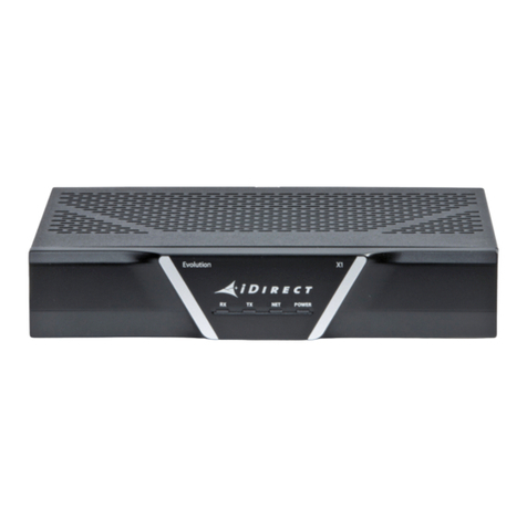
The X1 Router is shown in Figure 1-2. The router specifications are described in Section 2.1,
X1 Router Specifications on page 3. The front panel LEDs and rear panel connectors are
described in Section 3.1, X1 Indoor Router Interfaces on page 11.

2 Installation, Support, and Maintenance Guide
X1 Series Satellite Router
X1 Outdoor Router
Figure 1-1. Front and Rear View of the iDirect X1 Satellite Router (Indoor)
1.2 X1 Outdoor Router
The iDirect X1 Outdoor Satellite Router is a cost-effective remote bundle ideal for large,
narrowband networks for SCADA, femtocells or pipeline monitoring. There are three (3)
options for the X1 Outdoor Router:
• Option 1: 100 - 240 V AC
• Option 2: 12-36 V DC
• Option 3: 36-76 V DC
The X1 Outdoor Router features DVB-S2/ACM and TDMA, basic routing, VLAN functionality and
Quality of Service (QoS), and is embedded in a IP67 weatherproof enclosure enabling an
extended temperature range, and passive cooling.
The X1 Outdoor Router is shown in Figure 1-2. The router specifications are described in
Section 2.2, X1 Outdoor Router Specifications on page 7. The Router and Power Module front
panels and Router LED are described in Section 3.2, X1 Outdoor Router Interfaces on page 15.
Figure 1-2. X1 Outdoor Router (Left), and the Power Module (Right)

Installation, Support, and Maintenance Guide 3
X1 Series Satellite Router
2 Specifications
The specifications in this chapter describe the mechanical, environmental and RF
specifications for the X1 Series Satellite Router. The installation site must accommodate the
mechanical and environmental specifications of the X1 Router.
This chapter contains the following sections:
•Section 2.1, X1 Router Specifications on page 3
•Section 2.2, X1 Outdoor Router Specifications on page 7
NOTE: The X1 Router operates safely when it is used in accordance with its
marked electrical ratings and product usage instructions.
2.1 X1 Router Specifications
This section describes the mechanical, environmental, power, and RF specifications of the X1
Router . Options are described in Section 1.1, X1 Router on page 1 and Ta b l e 2-2 on page 4.
2.1.1 Mechanical and Environmental Specifications
The X1 Router mechanical and environmental specifications are defined in Ta b l e 2-1.
Tab l e 2-1. X1 Router Mechanical and Environmental Specifications
Category Description
Dimensions W 9 in (22.86 cm) x H 1.8 in (4.6 cm) x D 6.8 in (17.3 cm)
Weight Option 1-2: 1.8 lbs (0.82 kg)
Heat Dissipation 10 W (34.2 BTU/Hour)
Airflow Natural Convection Cooling
A m b i e n t Te m p e r a t u r e
Operational:
Storage:
+32Fto +122F (0C to +50C) at Sea Level
-40F to +176F (-40C to +80C)

4 Installation, Support, and Maintenance Guide
X1 Series Satellite Router
X1 Router Specifications
2.1.2 Power Specifications
Ta b l e 2-2 provides the power specifications for the router and the typical BUC/LNB for the X1
Router .
NOTE: Only use the iDirect approved and provided power supply.
Altitude
Operating:
Storage:
6,562 ft (2,000 m)
35,000 ft (9144 m)
Humidity
Operating: 10 - 90% non-condensing
5 - 95% non-condensing
Table 2-1. X1 Router Mechanical and Environmental Specifications (continued)
Category Description
Table 2-2. X1 Router Power Specifications
Category Description
Power Supply Input
Voltage Range and Power
(W)
Option 1: X1 (AC Power Supply): 100-240 VAC Single Phase to 24 VDC, 65 W
Option 2: X1-Ku/C Band (AC Power Supply): 100-240 VAC Single Phase to 24 VDC, 90 W
Frequency Option 1 and 2: 50-60 Hz
Power Supply Unit
Consumption
Option 1: 1.4 A (MAX)
Option 2: 1.2 A (MAX)
Router Input Power Option 1: +24 VDC, 2.7 A, 65 W (MAX)
Option 2: +24 VDC 3.75 A, 90 W (MAX)
NOTE: To avoid damaging the equipment or to prevent hardware failures, never connect
the 90W PSU to an X1 with 2.7A label.
X1 Router DC
Consumption
Option 1: 65 W (MAX)
Option 2: 90 W (MAX)
DC Power @ Tx Output
Connector
Option 1: +24 VDC @ 1.5 A (MAX) over operating temperature
Option 2: +24 VDC @ 2.1 A (MAX) over operating temperature
DC Power @ Rx Input
Connector
+24 VDC @ 300 mA (MAX)
Protection Internal, primary current fuse, inside power supply
Over current protection
Short circuit protection
Power Factor Correction Option 1, 2: Complies with EN61000-3-2 and EN61000-3-3
Input Transient Response 0.5 mS for 50% Load Change (TYP)

Installation, Support, and Maintenance Guide 5
X1 Series Satellite Router
X1 Router Specifications
2.1.3 RF Specifications
Ta b l e 2-3 defines the X1 Router RF specifications and Ta b l e 2-3 defines the TX SSB phase
noise parameters.
Power Supply Input
Power Connector
Option 1, 2: IEC-320-C6
Power Cord Option 1, 2: 18 AWG (American Wire Gauge)
Efficiency 88% (AVG)
Table 2-2. X1 Router Power Specifications (continued)
Category Description
Tab l e 2-3. X1 Router RF Specifications
Category Description
LNB Support Options 1-3:
Fsym > 10 Msps DRO LNB
Fsym > 1 Msps ±10 ppm PLL LNB
Fsym > 1 Msps ±35 ppm Uni-Ku LNB
Option 1-3: Internal reference LNBs only
Frequency Range
(Option 1, 2, 3) Transmit:
Receive:
950-1700 MHz
950-2150 MHz
Frequency Tuning Step Size
Transmit:
Receive:
0.6 Hz
Sub-Hertz with Demodulator
RF Power
Transmit:
Receive, Minimum:
Receive, Maximum:
Receive Adjustability:
-30 dBm to 0 dBm, 0.5 dB step
-130 + 10Log(Sym rate) dBm (Single carrier)
-5 dBm (Wideband Composite, MAX)
Under AGC for all valid Rx input power range

6 Installation, Support, and Maintenance Guide
X1 Series Satellite Router
X1 Router Specifications
Transmit SSB
Phase Noise
Typical Phase Jitter at
14 kHz to 1 MHz:
Frequency Offset L Band Phase Noise Options 1-3
dBc/Hz
0.1 kHz -60
1 kHz -70
10 kHz -80
100 kHz -90
≤1.8rms
Transmit Carrier Suppression ≤-40 dBc with output ≥-20 dBm
Discrete Spurs Out-of-band:
Option 1 and 2: < 50 dBc, with output ≥-20 dBm
In-band:
Option 1 and 2: ≤-32 dBc with output ≥-20 dBm
Modulator Spectral Shaping DVB-S2 (ETSI EN302307)
Transmitter On/Off Ratio 50 dB, with output power ≥-20 dBm
Table 2-4. Transmit Phase Noise Parameters
Transm it S S B
Phase Noise (dBc/Hz) frequency at: Band Phase Noise Option 1-3 dbC/Hz
0.01 kHz -29
0.1 kHz -59
1 kHz -69
10 kHz -79
100 kHz -89
1 MHz -100
Typical Phase Jitter at 14 kHz to 1 MHz: 1.8rms
Table 2-3. X1 Router RF Specifications (continued)
Category Description
Table of contents
Other iDirect Modem manuals
