Idis DC-TH Series User manual
DC-TH201x
Installation Guide
Thermal Cameras
DC-TH Series
DC-TH2011 DC-TH2011W / TH2012W DC-TH2011WR / TH2012WR


3DC-TH 201x Installation Guide
Table of Contents
1 Installation Method
1.1 Notes on Installation
1.2 Required Settings of Camera
1.3 How to Register to NVR or VMS
1.3.1 Connect with NVR
1.3.2 Connect with VMS on PC (IDIS Center & ISS Client)
1.4 Installation Method
2 Alarm Function
2.1 The Camera Alert Function
2.1.1 Alert on thermal image
2.1.2 Alert Using Relay Output
2.2 When using standalone NVR
2.3 When Using VMS on PC
2.3.1 Connecting to VMS through NVR
2.3.2 Connecting to VMS Directly
3 Hardware Factory Reset
4 Notes on Use
4
4
4
5
5
6
7
8
8
8
8
8
9
9
9
10
12
4DC-TH 201x Installation Guide
1. Installation Method
1.1 Notes on Installation
1.2 Required Settings of Camera
- This camera is designed for indoor use only and should be installed where constant temperature
can be maintained. Outdoor usage is strongly not recommended.
ㆍDo not point the camera towards the entrance or the outside of the building.
ㆍDeploy the solution indoors only in an environment with a constant temperature and no wind.
ㆍIt is recommended to set up a queuing area to manage the ow of people.
- Thermal sensor should measure human skin temperature. Therefore, for accurate scanning,
individuals must face the camera directly straight without wearing any hats, hoods, glasses, etc.
those might cover the facial skin.
- IPInstaller.exe is necessary for modifying the camera settings. This .exe le can be downloaded
from below link. (ID: admin / PW: Thermal#)
IPInstaller.exe
- Thermal sensor detects and alerts all the temperature that is higher than pre set-up ‘Event Max
Temperature’. In thermal image, there must not be any electronic equipment or devices possessing
heat. (e.g. smart phones, light, lamp, etc.)
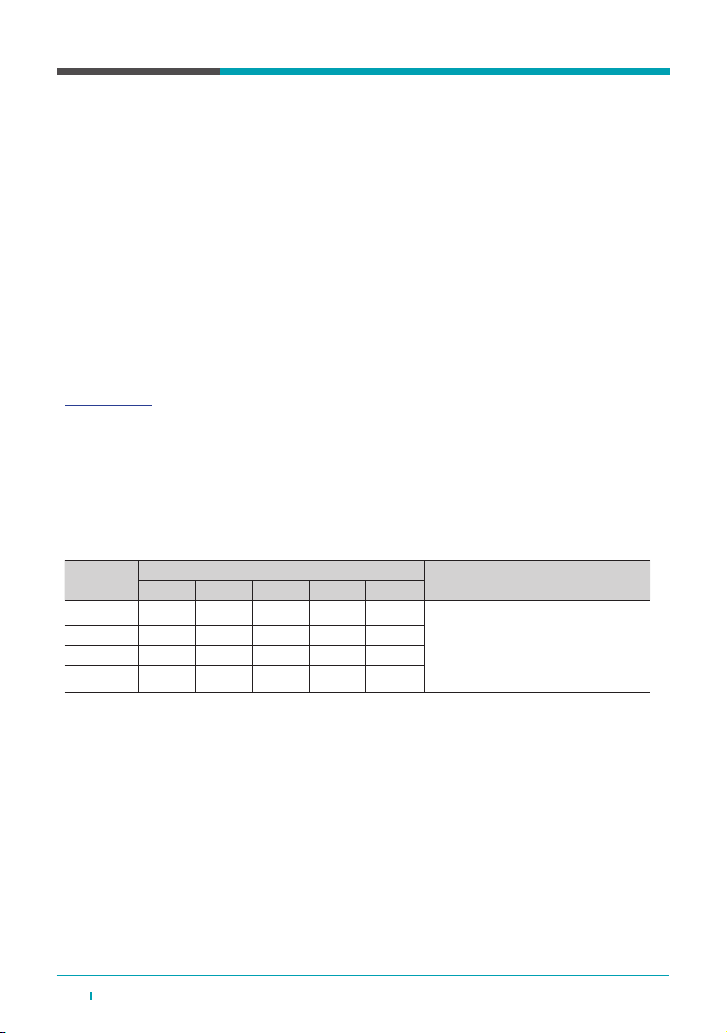
- Scanned temperature varies with distance from the camera. Below chart is our examination in
ofce. As shown from the chart, at least 0.5°C is decreased by a meter by meter. To minimize the
temperature difference, it is strong and highly recommended to install the camera and measure the
temperature within less than 2 meters from the moving subject.
Before registering the camera to NVR or VMS, all the required settings should be modied by using
IPInstaller.exe. Settings that must be modied are as below.
- IP address (the default IP address is 192.168.0.100)
- ID / PW : admin / Thermal#
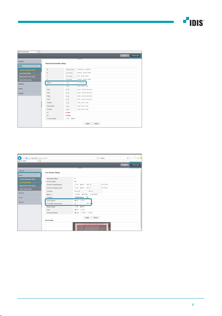
- Setting the proper temperature seen in the image
The temperature can be calibrated in SETUP – Video - Thermal Parameter Setup - Offset.
Dis.(m) Skin Temperature test (°C) Remark
1st 2nd 3rd 4th 5th
1 36.61 37.03 38.70 38.80 37.8 -The measured temperature is not xed
and varies by up to ± 0 to 1°C for each
distance.
- As the distance increases from the
cam, the temperature is generally lower.
- DC-TH2011 model
2 35.45 36.26 37.70 38.10 36.8
3 34.99 35.58 37.30 37.50 36.50
4 35.06 35.13 36.60 36.50 35.50
※The skin temperature varies according to environment and person. So calibration is required based on each user. When installing, the
user must run several tests and gain data like the above chart and then determine proper ‘Event Max Temperature’. For example, refer-
ring to above chart data, it would be proper to set ‘Event Max Temperature’ 38°C . If so, the event alarm will mostly be active around
one meter or closer. After alarm, a user must measure the temperature once more by a thermometer for accuracy.
5DC-TH 201x Installation Guide
1.3 How to Register to NVR or VMS
1.3.1 Connect with NVR
DC-TH201x can be used by connecting with NVR. The compatible NVR versions are as below.
- DR-63xx v7.0.2 or higher
- DR-23xx, 24xx v7.0.2 or higher
※ Refer to [QG_DC-TH Series] for registration and alert conguration
- Setting threshold temperature
The threshold temperature can be set in SET Temperature’.UP - Video - Live Screen Setup.
Tick ‘ON’ of the ‘Event Report’ and setup ‘Event Max
6DC-TH 201x Installation Guide
※The network IP address (subnet) of WAN / V-IN must be set differently. Refer to 3.2 When using
standalone NVR.
※The streaming resolution has to be changed in NVR side. Refer to 3. Notes on Use.
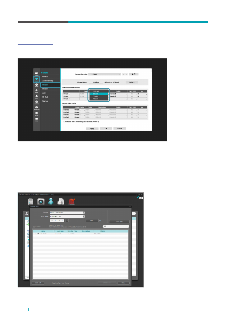
1.3.2 Connect with VMS on PC (IDIS Center & ISS Client)
DC-TH201x can be used by connecting with VMS. In this case, there are two ways to connect to
VMS. First is registering NVR which has already registered DC-TH201x. Second is registering the
DC-TH201x directly to VMS.
※ When registering DC-TH201x to VMS, the protocol must be ONVIF Conformance as screenshot below
※ Recording schedule can be set either MotionEvent or TimeLapse.

7DC-TH 201x Installation Guide
1.4 Installation Method
It is highly and particularly recommended that the camera only be used for detecting xed subjects
to guarantee accurate temperature.
Please install and apply the camera as instructed below.
1) Place the camera indoor where constant temperature can be maintained.
2) Set the guideline to guide the subject to target position; for example, markings like shoe shape
or cross. This target position would be a few meters straight from the camera depending on the
installed location.
3) Maintain the position and look straight to the camera for a few seconds.
4-1) If alarm triggers, measure the person’s body temperature with a thermometer.
4-2) If not, you may allow the entrance.
8DC-TH 201x Installation Guide
2. Alarm Function
2.1 The Camera Alert Function
2.1.1 Alert on Thermal Image
2.1.2 Alert Using Relay Output
2.2 When Using Standalone NVR
As mentioned in ‘How to register to NVR or NMS’, the camera can be connected with NVR or VMS.
Either device, the alert image is the same.
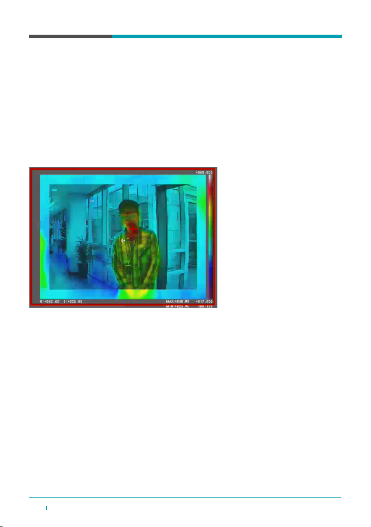
When temperature higher than pre set-up ‘Event Max Temperature’ is detected, the image is
highlighted in a red box and the temperature point is marked with a red cross as below picture.
DC-TH201x has Relay Output cable so using siren or ash light by connecting camera alarm-out
is possible. In camera menu – Live Screen Setup, check Relay Output ‘ON’. When temperature is
detected, event trigger will be generated through Relay Output cable.
(Tick sound can be heard from the camera.)
When using standalone NVR with DC-TH201x, alarm is generated from DC-TH201x to NVR as
motion event. Refer to [QG_DC-TH Series] for detailed settings.
※ To receive motion event and generate beep sound, the network IP address (subnet) of V-IN and
WAN must be set differently.
e.g. V-IN network - NVR 192.168.0.200
- CAM 192.168.0.100
WAN network - 10.0.18.80

9DC-TH 201x Installation Guide
2.3 When using VMS on PC
2.3.1 Connecting to VMS through NVR
2.3.2 Connecting to VMS Directly
As mentioned in ‘1.3.2 Connect with VMS on PC (IDIS Center & ISS Client)’, there are two ways to
connect DC-TH201x to VMS.
When connected to PC through NVR and the motion alarm is generated triggering the ‘Event Max
Temperature’, Event is sent properly to VMS.
When connected to VMS directly, the Event comes in as motion alarm as the below screenshot.
※ Note: When the resolution of the camera changes it takes about a minute for ISS to receive the event from the
camera.
10 DC-TH 201x Installation Guide
3. Hardware Factory Reset
※ Wear an anti-static bracelet and insulating gloves before resetting the device.
※ When resetting the camera, keep the power on.
※ For W/WR model, factory reset function is applied from F/W version
‘HiDual_V5.0.1.200603-060309’
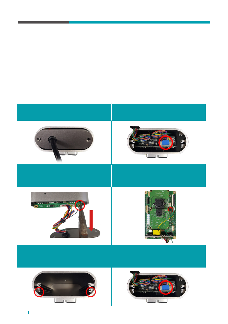
3.1 DC-TH2011
1. Loosen the M3x08 screws at the bottom
of DC-TH2011.
2. Remove the thermal pad attached to the
12P cable housing.
5. Assemble the camera in reverse order.
- Be aware of the M/B slide
- Pay attention to the position of the thermal pad and reattach it (12P cable housing)
3. Using a plier, grasp the ground hole of
the M/B and pull down.
4. Press the hard reset button located on the
M/B for 7-8 seconds. The reset takes
about a minute to be completed.

11DC-TH 201x Installation Guide
3.2 DC-TH2011W/2W
3.3 DC-TH2011WR/2WR
1. Loosen the bolts on the back of
DC-TH2011W/12W using a hexagon
wrench
2. Press M/B Factory reset button for
5 seconds
1. Loosen the screws on the back of
DC-TH2011WR/12WR.
2. Press M/B Factory reset button for
5 seconds

12 DC-TH 201x Installation Guide
4. Notes on Use
1.1 Notes on installation
- When the camera is registered to NVR for the rst time, the default resolution is set as the
highest - the visual mode resolution. Therefore, the resolution must be adjusted to thermal image
viewable resolution referred in below table.
- Do not change any options other than instructed. When modifying camera settings using IPInstaller.
exe - Device web, only setups regarding Video (Thermal Parameter Setup - Offset, Live Screen
Setup, Video Stream Setup) and Network should be modied. Changing other setup might cause
an error.
- When registering the camera to NVR or ISS by Onvif conformance Protocol, the Auto Scan(LAN)
Mode is not supported. Refer to [QG_DC-TH Series] for registration.
Model Thermal Camera Mode Visual Mode
(Not Thermal Mode)
DC-TH2011 800 x 600, 720 x 540 1280 x 960
DC-TH2012 1920 x 1080, 1280 x 720, 1024 x 768, 640 x 480 2592 x 1944, 2048 x 1536, 1600 x 1200
※ If the resolution is changed from the camera side, the changed resolution is applied in NVR’s
Live image. The changed resolution can be checked by right clicking > Information on the Live
image. However, the NVR’s CAMERA > Stream I > Stream1 resolution does not match
automatically. In this case, there is no problem in use, but if you want to match the resolution,
you can do it manually by changing the resolution in NVR side.’

13DC-TH 201x Installation Guide
MEMO

For more information, please visit
www.idisglobal.com
IDIS and identifying product names and numbers herein are registered trademarks of IDIS Co., Ltd. All non-IDIS brands and product names
are trademarks or registered trademarks of their respective companies. Product appearance, build status, and/or specications are subject to
change without notice. Copyright © IDIS Co., Ltd. All rights reserved.
Other manuals for DC-TH Series
1
This manual suits for next models
6
Table of contents
Other Idis Thermal Camera manuals


