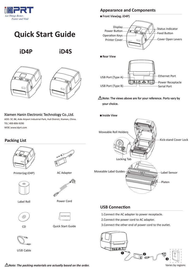
iDPRT ID4 Series User manual

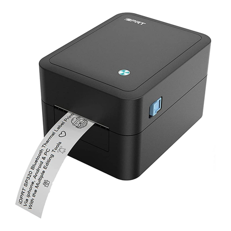
Label Printer
Service Manual
ID4 IE4 Series
IE4P
IE4S
ID4S
ID4P

Rev:1.0
1
Document Change Record
This page records changes to this document. The document was originally released as Revision
1.0.
Version Number
Date
Description of Change
Rev.1.0
2018.01.17
First Edition.

ID4/IE4 Series •Service Manual
Rev:1.0
2
Foreword
This manual describes the label printer —ID4/IE4 series.
It is designed for use as a reference for periodic inspections and maintenance procedure to be
executed by service person. It is not intended for the general user. Users of this manual should
have a basic knowledge and understanding of English language.
This manual is divided into the following sections:
CHAPTER 1 Parts Replacement
CHAPTER 2 Troubleshooting
CHAPTER 3 Parts List

ID4/IE4 Series •Service Manual
Rev:1.0
3
Note the following precautions during work.
Note:
Always wear safety gloves to prevent an injury as well as to prevent rust developing on the
device.
Never start a service when your hands are wet. This will prevent an electric shock as well as
rust developing on the device.
Always wear a wristband to prevent a damage by electrostatic discharge.
The contents of this manual are subject to change without notice.
Copyright © Xiamen Hanin Electronic Technology Co., Ltd
.
Important Information
更改记录
Note

ID4/IE4 Series •Service Manual
Rev:1.0
4
CONTENT
CHAPTER 1 PARTS REPLACEMENT/MODULE PURCHASE LIST FOR SERVICE .........................................................6
Parts Replacement ................................................................................................................................7
1.0 Print Header Module.......................................................................................................................7
1.1 Platen Module ...............................................................................................................................11
1.2 Motor Module ...............................................................................................................................13
1.3 Main-Board, Core-Board and Button-Battery Module..................................................................17
1.4 Display Module..............................................................................................................................25
1.5 Power Switch Module ...................................................................................................................27
1.6 Arrow Key Module.........................................................................................................................29
1.7 Feed Button Module......................................................................................................................31
1.8 Upper photoelectric Module.........................................................................................................35
1.9 Lower Photoelectric Module .........................................................................................................37
1.10 Micro switch Module...................................................................................................................41
1.11 Ribbon Detection Module ...........................................................................................................43
1.12 Left and Right Roll Holder Module ..............................................................................................44
1.13 iWLM Module..............................................................................................................................46
1.14 Cutter Module .............................................................................................................................47
1.15 Peeler Module .............................................................................................................................48
1.16 Power Cord..................................................................................................................................49
1.17 Power Adapter ............................................................................................................................49
1.18 External Paper Roll Stand ............................................................................................................50
Module Purchase for Service...............................................................................................................51
CHAPTER 2 TROUBLESHOOTING .........................................................................................................................52
2.1 Troubleshooting Procedure...................................................................................................................53
2.2 Troubleshooting ....................................................................................................................................54
2.3 Service Process ......................................................................................................................................57

ID4/IE4 Series •Service Manual
Rev:1.0
5
CHAPTER 3 PARTS LIST ........................................................................................................................................59
3.1 The Exploded View ................................................................................................................................60
3.2 Service Parts ..........................................................................................................................................68

ID4/IE4 Series •Service Manual
Rev:1.0
6
Chapter 1 Parts Replacement/Module Purchase List for Service
This chapter explains disassembly and reassembly of the printer.
Note the following precautions during disassembly and reassembly.
• Turn off the power supply before disassembling the printer.
• Always wear safety gloves to prevent an injury as well as to prevent rust developing on the
device.
• Never start a service when your hands are wet. This will prevent an electric shock as well as
rust developing on the device.
• Always wear a wrist strap to prevent the damage by electrostatic discharge. Assembly is the
reverse of disassembly unless otherwise specified.
• Assembly is the reverse of disassembly unless otherwise specified.
CONTENT
1.0 Print Header Module
1.1 Platen Module
1.2 Motor Module
1.3 Main-Board, Core-Board and
Button-Battery Module
1.4 Display Module
1.5 Power Switch Module
1.6 Arrow Key Module
1.7 Feed Button Module
1.8 Upper photoelectric Module
1.9 Lower Photoelectric Module
1.10 Micro switch Module
1.11 Ribbon Detection Module
1.12 Left and Right Roll Holder Module
1.13 iWLM Module
1.14 Cutter Module
1.15 Peeler Module
1.16 Power Cord
1.17 Power Adapter
1.18 External Paper Roll Stand

ID4/IE4 Series •Service Manual
Rev:1.0
7
Parts Replacement
1.0 Print Header Module
1. Firstly, open the top cover. Then press the TPH print header inward by hands and slide it down.
2. Remove TPH from TPH bracket.
3. Finally, unscrew the 3.0*5.0 screws and separate ground wire from TPH bracket.
Disassembling the module:
Replacing print header module:
Note: please refer to iD4P/S Print Head Module Quick Start Guide
Applicable Module: iD4P

ID4/IE4 Series •Service Manual
Rev:1.0
8
1. Firstly, open the top cover. Then press the TPH print header inward by hands and slide it down.
2. Remove TPH from TPH bracket.
3. Finally, unscrew the 3.0*5.0 screws and separate ground wire from TPH bracket.
Disassembling the module:
Replacing print header module:
Note: please refer to iD4P/S Print Head Module Quick Start Guide
Applicable Module: iD4S

ID4/IE4 Series •Service Manual
Rev:1.0
9
1. Firstly, open the top cover. Then press the TPH print header inward by hands and slide it down.
2. unscrew two 3.0*6.0 screws and remove TPH from TPH bracket.
3. Remove the TPH cable from TPH.
4. Finally, unscrew the 3.0*5.0 screw and take out ground wire.
Disassembling the module:
Replacing print header module:
Note: please refer to iE4P Print Head Module Quick Start Guide
Applicable Module: iE4P

ID4/IE4 Series •Service Manual
Rev:1.0
10
1. Firstly, open the top cover. Then press the TPH print header inward by hands and slide it down.
2. Remove the TPH cable from TPH.
3. Finally, unscrew the 3.0*5.0 screw and remove the ground wire from TPH.
Disassembling the module:
Replacing print header module:
Note: please refer to iE4S Print Head Module Quick Start Guide
Caution: Please do not touch the TPH in case of electric shock for TPH damage during
disassembling the print head.
Applicable Module: iE4S

ID4/IE4 Series •Service Manual
Rev:1.0
11
1.1 Platen Module
1. Using nippers, remove the tip of platen sleeves from the main body.
2. Rotate the platen roller sleeves 90 degrees counterclockwise, and pull out the two sleeves
simultaneously.
Disassembling the module:
Replacing platen module:
Applicable Module: iD4P/ iD4s

ID4/IE4 Series •Service Manual
Rev:1.0
12
1. Using nippers, remove the tip of platen sleeves from the main body.
2. Rotate the platen roller sleeves 90 degrees counterclockwise, and pull out the two sleeves
simultaneously.
Disassembling the module:
Replacing platen module:
Applicable Module: iE4P/ iE4s

ID4/IE4 Series •Service Manual
Rev:1.0
13
1.2 Motor Module
1. Firstly, unscrew four 3.0*8.0 screws to separate lower cover from lower bracket by cross
screwdriver.
2. Secondly, unscrew four 4.0*8.0 screws to remove motor module.
Disassembling the module:
Replacing motor module:
Applicable Module: iD4P

ID4/IE4 Series •Service Manual
Rev:1.0
14
1. Firstly, unscrew four 3.0*8.0 screws to separate lower cover from lower bracket.
2. Secondly, unscrew four 4.0*8.0 screws to remove motor module.
Disassembling the module:
Replacing motor module:
Applicable Module: iD4S

ID4/IE4 Series •Service Manual
Rev:1.0
15
1. Firstly, unscrew four 3.0*8.0 screws to separate lower cover from lower bracket.
2. Secondly, unscrew four 4.0*8.0 screws to remove motor module.
Disassembling the module:
Replacing motor module:
Applicable Module: iE4P

ID4/IE4 Series •Service Manual
Rev:1.0
16
1. Firstly, unscrew four 3.0*8.0 screws to separate lower cover from lower bracket.
2. Secondly, unscrew four 4.0*8.0 screws to remove motor module.
Disassembling the module:
Replacing motor module:
Applicable Module: iE4S

ID4/IE4 Series •Service Manual
Rev:1.0
17
1.3 Main-Board, Core-Board and Button-Battery Module
1. Firstly, unscrew four 3.0*8.0 screws to separate lower cover from lower bracket.
2. Then unscrew the 2.0*3.0 screw to remove the COM port baffle.
3. Finally, unscrew four 3.0*6.0 screws, remove the main-board from lower bracket.
4. Take out the core-board and button-battery.
Disassembling the module:
Applicable Module: iD4P

ID4/IE4 Series •Service Manual
Rev:1.0
18
Replacing main-board:
Replacing button-battery:
Replacing core-board:

ID4/IE4 Series •Service Manual
Rev:1.0
19
1. Firstly, unscrew four 3.0*8.0 screws to separate lower cover from lower bracket.
2. Then unscrew the 2.0*3.0 screw to remove the COM port baffle.
3. Finally, unscrew four 3.0*6.0 screws, remove the main-board from lower bracket.
4. Take out the core-board and button-battery.
Disassembling the module:
Applicable Module: iD4S
This manual suits for next models
5
Table of contents
Other iDPRT Label Maker manuals
Popular Label Maker manuals by other brands
CTM
CTM 360a series Maintenance and service manual

Brother
Brother P-Touch PT-D210 user guide
Brother
Brother QL-1100 Quick setup guide
Brother
Brother P-touch PT-2030 user guide

Dymo
Dymo LabelWriter 450 Duo Label Printer quick start guide

Brother
Brother QL 570 - P-Touch B/W Direct Thermal Printer Setup & operation guide
