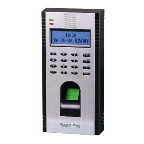
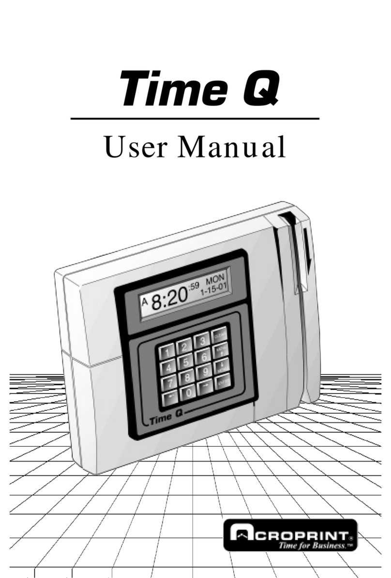
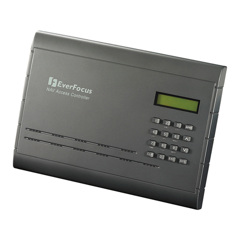
IDTECH LX505 User manual

Quick Installation Guide
Proximity / PIN Access Controller

※LX505/LX505SR QUICK INSTALLATION GUIDE
2
1. WHAT‟S INCLUDED
Please unpack and check the contents of the box. If any of these parts are missing, please contact a nearby distributor
or IDTECK.
LX505/LX505R
Wall Mount
Manual CD
Quick installation Guide
2PIN connector (1ea)
3PIN connector (1ea)
4PIN connector (1ea)
5PIN connector (1ea)
6PIN connector (1ea)
8PIN connector (1ea)
Diode (2ea)
2.2K resister (4ea)
3.5 X 40mm screws (4ea)
3.5 X 12mm screws (4ea)
3 X 8mm screws (1ea)
6 X 30mm screws (4ea)

※LX505/LX505SR QUICK INSTALLATION GUIDE
3
2. PARTS CODE AND DESCRIPTION
2.1 Front Panel
Code
Description
○
1LCD
This module displays the operation status of LX505/LX505SR.
○
2System Status LED
The red LED turns on when Power is supplied.
The green LED turns on when relay #1 becomes active.
The yellow LED turns on when relay #2 becomes active.
○
3Menu Button
There are 12 menu buttons (F1 to F12). Press a menu button to enter the
corresponding menu. (F10 to F12 menu buttons are unavailable for LX505/LX505SR)
○
4Input Button
It is the numerical button to input number or to define direction.
: Left/right direction buttons
: Up/down direction buttons
: Select button
: Cancel button
○
1
○
2
○
4
○
3
4
6
2
ENT
ESC
8

※LX505/LX505SR QUICK INSTALLATION GUIDE
4
2.2 The Back of Panel
Code
Description
○
1RJ45 Connector
Connect the RJ45 jack and use it in case of TCP/IP communication.
○
2Tamper Switch
If someone disassembles the installed LX505/LX505SR on wall by force, the tamper
switch is activated then buzzer makes sound.
○
32PIN Connector
Connect the power cable.
○
43PIN Connector
Connect the RS232 communication cable to connect serial print.
○
56PIN Connector
Connect the input and output cable.
○
68PIN Connector
Connect the relay cable.
○
7Initialization Switch
This is used to initialize LX505/LX505SR.
○
8LED
These LED indicate Communication status.
○
94PIN Connector
This is the Preliminary connector for extension of function.
○
10 5PIN Connector
Connect the RS232, RS485 communication cable.
○
1
○
2
○
3
○
4
○
5
○
6
○
7
○
8
○
9
○
10

※LX505/LX505SR QUICK INSTALLATION GUIDE
5
2.3 Connection and Color Code Table
I/O PORT NAME
SIGNAL NAME
WIRE COLOR
CON-1(2PIN CONNECTOR)
Main Power (+12V)
Main Power (+12V)
Red
Power Ground
Power Ground
Black
CON-2 (3PIN CONNECTOR : SERIAL PRINTER)
RS232-RX
RS232-RX
Pink wire with white stripe
RS232-TX
RS232-TX
Cyan wire with white stripe
RS232-GND
RS232-GND
Black
CON-3 (6PIN CONNECTOR)
TTL Output #1
TTL Output #1
Orange wire with white stripe
TTL Output #2
TTL Output #2
Brown wire with white stripe
Aux Input #1
Aux Input #1
Green
Aux Input #2
Aux Input #2
Green wire with white stripe
Wiegand Data 0
Wiegand Data 0
Pink
Wiegand Data 1
Wiegand Data 1
Cyan
CON-4 (5PIN CONNECTOR)
RS485-RTX(+)
RS485-RTX(+)
Yellow wire
RS485-RTX(-)
RS485-RTX(-)
Gray wire
RS232-TX
RS232-TX
Black wire with white stripe
RS232-RX
RS232-RX
Red wire with white stripe
RS232-GND
RS232-GND
Black
CON-5 (8PIN CONNECTOR)
Door Relay(NC)
NC(1)
Blue wire with white stripe
Door Relay(COM)
COM(1)
Gray wire with red stripe
Door Relay (NO)
NO(1)
White wire with red stripe
Alarm Relay(NC)
NC(2)
Purple wire with white stripe
Alarm Relay(COM)
COM(2)
White
Alarm Relay(NO)
NO(2)
Purple
Exit Button
Exit
Orange
Door Sensor
Contact
Yellow wire with red stripe
CON-6 (4PIN CONNECTOR : DOOR PHONE (RESERVED))
DP_VCC
Orange wire with red wire
DP_GND
Orange wire with black stripe
DP_D0
Data-0
Blue
DP_D1
Data-1
Brown
CON-7: TCP/IP RJ45 CONNECTOR

※LX505/LX505SR QUICK INSTALLATION GUIDE
6
3. SYSTEM CONFIGURATION
(Figure: System Configuration)
RS232/RS485 Converter
Host PC
DC12V Power Supply
DC12V Power Supply
RS232
RS485
RS485
Exit Button
RF Reader
RF Reader
Door Lock
Exit Button
Door Lock

※LX505/LX505SR QUICK INSTALLATION GUIDE
7
4. INSTALLATION
4.1 Wall Mount Installation
Install LX505/LX505SR as the procedure below.
1. Position the Wall Mount to the location where you want to install the unit and mark 4 x drilling positions. Drill 6-32
holes for at least 4 mounting points.
2. Drill a 1/2” hole on the center of the Wall Mount.
3. Using 4 screws, install the Wall Mount to the proper location.
4. Take out the cable through the center hole.
5. After the wiring is done, put the LX505/LX505SR on the Wall Mount and screw it.
.
(Figure: Wall Mount)
Do not install LX505/LX505SR on a metal wall. Otherwise, the radio frequency from the metal frame will
make reading range of the card shorter.
Caution

※LX505/LX505SR QUICK INSTALLATION GUIDE
8
5. CONNECTION
5.1 Power Connection
- Connect DC 12V (+) wire of Power Supply to Red wire of LX505/LX505R.
- Connect GND (-) wire of Power Supply to Black wire of LX505/LX505R.
5.2 Input Connection
(Figure: Input Connection)
1. Connect the DC 12V(+) wire of the power supply to the red wire of LX505/LX505SR.
2. Connect the GND(-)wire of the power supply to the black wire of LX505/LX505SR.
Exit Button Connection
- Connect one wire of Exit Button to Orange wire of LX505/LX505SR.
- Connect the other wire of Exit Button to GND of LX505/LX505SR.
Door Contact Sensor Connection
- Connect one wire of Door Contact Sensor to Yellow with Red stripe wire of LX505/LX505SR.
- Connect the other wire of Door Contact Sensor to GND of LX505/LX505SR.
Auxiliary Input Device Connection
(Applicable to Aux Input #1(Green wire), Aux Input #2(Green with white stripe wire))
- Connect one wire of Auxiliary Input Device to one of Aux Input #1 or Aux Input #2 of LX505/LX505SR.
- Connect the other wire from Auxiliary Input Device to GND of LX505/LX505SR.
Door Contact Sensor
Exit Button
Power Supply
Yellow with red stripes
GND
GND
Orange
GND (-)
DC 12V(+)
2.2K Resistor
2.2K Resistor
Red
Black

※LX505/LX505SR QUICK INSTALLATION GUIDE
9
You have to connect a 2.2K resistor between the input wire and the GND for the Cut Off Check function.
Select whether or not to check the cut off status of each device in „Cut Off Check‟ of [F5 SETUP MENU].
Next, set the output format that will be generated in the event of a cutoff in „Cut Off Alarm‟ of [F5 SETUP
MENU].
5.3 Output Connection
(Figure: Input Connection)
Door Relay Connection for Power Fail Safe Door Lock
- Connect COM wire of Door Relay (Gray with Red stripe) to +12V.
- Connect NC wire of Door Relay (Blue with White stripe) to (+) wire of Door Lock.
- Connect GND(-) wire to (-) wire of Door Lock.
Door Relay Connection for Power Fail Secure Door Lock
- Connect COM wire of Door Relay (Gray wire with Red stripe) to +12V.
Caution
Door
Relay
Alarm
Relay
COM(gray with red stripe)
NO(white with red stripe)
NC(blue with white stripes))
COM(white)
NO(purple)
NC(purple with white stripes)
DC12V Power Supply
Power Fail Safe
Door Lock
Power Fail Secure
Door Lock
Alarm
Device
GND(-)
DC 12V(+)
(-)
(+)
(+)
(+)
(-)
(-)
Diode
Diode
Diode
Cathode
Anode

※LX505/LX505SR QUICK INSTALLATION GUIDE
10
- Connect NO wire of Door Relay (White with Red stripe) to (+) wire of Door Lock
- Connect GND(-) wire to (-) wire of Door Lock.
Alarm Relay connection
- Connect COM wire of Alarm Relay (White) to +12V of Power Supply.
- Connect NO wire of Alarm Relay (Purple) to (+) wire of Alarm Device.
- Connect (-) wire of Alarm device to GND (-) of Power Supply.
It is strongly recommended to connect a reverse diode as shown above when wiring Door Lock or Alarm.
If you don‟t connect reverse diode, external noise appears then it causes some malfunctions such as
poor communication, unintended changes in system setting etc. Also if you connect the diode to contrary
polarity, the diode will be burnt due to high current, so must connect it in the correct direction. 1N4004 –
1N4007 or equivalent diode are included in the gift box.
24V Door Lock and Automatic Door Connection
When you control 24V door lock or automatic door, wire the door lock depending on Power Fail Safe or Power Fail
Secure. But separate power source must be applied and use external Relay in both Power Fail Secure and Power
Fail Safe door lock.
(Figure: 24V Door Lock and Automatic Door Connection)
If you don‟t use separate power source and external Relay for the 24V door lock, relay of LX505/LX505SR
may have damages and some malfunctions will appear.
Caution
Caution

※LX505/LX505SR QUICK INSTALLATION GUIDE
11
5.4 External Reader Connection
(Figure: External Reader Connection)
Proximity Reader Connection
- Connect (+) wire of the Proximity Reader to DC +12V of power supply.
- Connect (-) wire of the Proximity Reader to GND(-) of power supply.
- Connect Data-0 wire of the Proximity Reader to the Pink wire of LX505/LX505SR.
- Connect Data-1 wire of the Proximity Reader to the Sky Blue wire of LX505/LX505SR.
Compatible Readers (External Reader)
LX505:
- Standard 26bit Wiegand format proximity readers
- Standard 26bit Wiegand + 8bit burst format proximity and keypad reader
LX505SR:
- Standard 34bit Wiegand format proximity reader
- Standard 34bit Wiegand + 8bit burst format proximity and keypad reader
Wiegand Data 0(Pink)
Wiegand Data 1(Sky blue)
DC12V (+)
GND (-)
+ (Red)
Power Supply
- (Black)
Proximity Reader

※LX505/LX505SR QUICK INSTALLATION GUIDE
12
5.5 Communication Connection
5.5.1 RS232 Communication Port Connection
To connect between LX505/LX505R and host PC, A 9-pin connector (Serial communication connector, female) is
needed to connect the LX505/LX505SR with a host PC via RS232 communication. Please follow the steps below.
(Figure: RS232 Communication Connection)
- Connect RS232-TX (Black with White stripe wire) of LX505/LX505SR to the pin #2 (RXD) of 9-pin connector.
- Connect RS232-RX (Red with White stripe wire) of LX505/LX505SR to the pin #3 (TX) of 9-pin connector.
- Connect GND (Black wire) to the pin #5 of the 9-pin connector.
- Plug in the 9-pin female connector to COM1 or COM2 Port of the Host PC.
- Install and run the LX505/LX505SR application software(STARWATCH TIME PRO, LX ACCES PRO II,
STARWATCH STANDARD).
Black with White stripe wire
Red with White stripe wire
Black
RS232 Communication
9 Pin Female
Connector
2
3
5
Host PC

※LX505/LX505SR QUICK INSTALLATION GUIDE
13
5.5.2 RS485 Communication Connection for Standalone Unit
An RS485/RS232 converter is needed to for RS485 communication between the LX505/LX505SR and a host PC.
Please follow the steps below.
(Figure: RS485 Communication Connection for standalone unit)
- Connect RS485-RTX (+) (Yellow wire) of LX505/LX505SR to RS485-A port of the converter.
- Connect RS485-RTX (-) (Gray wire) of LX505/LX505SR to RS485-B port of the converter.
- Plug the 9-pin connector of the converter into the COM1 or COM2 port of the host PC.
- Install then run the LX505/LX505SR application software (STARWATCH TIME PRO, LX ACCESS PRO II,
STARWATCH STANDARD).
When you connect RS232/RS485 converter with LX505/LX505SR, connect Termination Resistor to both of
beginning and end points of the wire as the figure above. If the length of communication wire is too long
in one communication loop, it causes communication problem from the cracked data or decrement. To
prevent it, connect Termination Resistor as the figure above. But, don‟t use Termination Resistor for short-
distance communication wire. If you use Termination Resistor in short-distance, it could cause
communication errors.
RS485
RS232
Host PC
RS485/RS232
Convertor
Max. 1200m
Gray
Yellow
Termination
Resister
Termination
Resistor
Caution

※LX505/LX505SR QUICK INSTALLATION GUIDE
14
5.5.3 RS485 Communication Connection for Multiple Units
An RS485/RS232 converter is needed for RS485 communication between LX505/LX505SR and a host PC.
Please follow the instructions below.
(Figure: RS485 Communication Connection for Multiple Units)
First, connect RS485 port of all LX505/LX505SRs in parallel. (Maximum of 32 LX505/LX505SR)
- Connect RS485-RTX (+) (Yellow wire) of one LX505/LX505SR to RS485-RTX (+) (Yellow wire) of another
LX505/LX505SR.
- Connect RS485-RTX (-) (Gray wire) of one LX505/LX505SR to RS485-RTX (-) (Gray wire) of another
LX505/LX505SR.
- Set a unique Communication Address of each LX505/LX505SR.
Second, connect RS485 port of the first LX505/LX505SR to the RS485/RS232 converter.
- Connect RS485-RTX (+) (Yellow wire) of the LX505/LX505SR to RS485-A port of the converter.
- Connect RS485-RTX (-) (Gray wire) of the LX505/LX505SR to RS485-B port of the converter.
- Plug the 9-pin connector of the converter into the COM port of the host PC.
- Install and run the LX505/LX505ST application software (STARWATCH TIME PRO, LX ACCESS PRO II,
STARWATCH STANDARD).
When you connect RS232/RS485 Converter with LX505/LX505SR, connect Termination Register to both of
the beginning and end points of the wire as the figure above. If the length of communication wire is too
long in one communication loop, it causes communication problem from the cracked data or decrement.
To prevent it, connect Termination Register as the figure above. But, don‟t use Termination Resistor for
short-distance communication wire. If you use it in short-distance, it could cause communication errors.
RS485/RS232
Converter
Host PC
RS232
RS485
Max. 1200m
Gray
Yellow
Termination
Resistor
Termination
Resister
Last LX505/LX505R
First LX505/LX505SR
Caution

※LX505/LX505SR QUICK INSTALLATION GUIDE
15
5.5.4 TCP/IP Communication Connection (Only for LX505T/LX505SRT)
Follow the instruction below for TCP/IP communication.
(Figure: TCP/IP Communication between Multiple LX505 units and a host PC)
- Connect the RJ45 plug of LAN cable from the HUB to the RJ45 jack of the LX505T/LX505SRT.
- Set a unique Communication Address of each LX505T/LX505SRT.
- Install then run the LX505T/LX505SRT application software (STARWATCH TIME PRO, LX ACCESS PRO II,
STARWATCH STANDARD).
TCP/IP Module (IIM7100A) Setting
For TCP/IP communication, set information for Network and Serial communication through TCP/IP
Module(IIM7100) setting program(IIM100A Configuration Tool).
1. Install TCP/IP Module(IIM7100) setting program, IIM100A Configuration Tool.
The Program to set network and check operation status is contained in Application software (TARWATCH
TIME PRO, LX ACCESS PRO II, STARWATCH STANDARD) CD. Install „IIM100A Configuration Tool‟and
then set TCP/IP Module information for communication environment.
2. Network Information Setting
After TCP/IP Module(IIM7100) setting program(IIM100A Configuration Tool) is installed, run „Start‟-
> ‟Progrm‟-> Wiznet _C.exe.
1) If program is normally run, this screen below is displayed.

※LX505/LX505SR QUICK INSTALLATION GUIDE
16
2) To search TCP/IP Module connected with LX505/LX505SR controller, click ‘Search’button.
3) All TCP/IP Modules connected on network are displayed. In the ‘Board List’, MAC address of TCP /IP
Module is displayed.
4) Check MAC address of TCP/IP Module (described on TCP/IP module) and then select it. Setting
information is displayed as below.

※LX505/LX505SR QUICK INSTALLATION GUIDE
17
5) Select „Network‟tab.
Input network information of selected TCP/IP module to „Local IP‟, „Subnet‟, „Gateway‟.
Network information can be assigned from network manager.
Input „5000‟for „Port‟, „0.0.0.0‟for „Server IP‟(default), „0‟for „Server IP Port‟. Select „Server Mode‟for
„Network Mode‟. Refer to table below.
Column Name
Setting Value
Local IP
The IP address assigned from corresponding network (Not duplicated)
Gateway
The Gateway assigned from corresponding network (Not duplicated)
Subnet Mask
The Subnet Mask assigned from corresponding network (Not duplicated)
Port (above)
5000
Server IP
0.0.0.0
Port (below)
0
Mode
Server Mode
6) Select „Serial‟tab.
Select serial communication setting value („Speed‟, „Data Bit‟, „Parity‟, „Stop Bit‟, „Flow‟) of selected TCP/IP
module.
Select „57600‟for „Speed‟, „8‟for „Data Bit‟, „None‟for „Parity‟„1‟for „Stop Bit‟„CTS/RTS‟for „Flow‟. Refer to
table below.
Column Name
Setting Value
Speed
57600
DataBit
8
Parity
None
Stop Bit
1
Flow
CTS/RTS
7) Select „Option‟tab.
Select option values („Inactivity Time‟, „Time‟, „Size‟ and „Char‟ ) of selected TCP/IP module.
Select „30000‟for „Inactivity Time‟, „0‟for „Time‟, „0‟for „Size‟, „00‟for „Char‟. Refer to table below.
57600

※LX505/LX505SR QUICK INSTALLATION GUIDE
18
Column Name
Setting Value
Inactivity Time
30000
Time
0
Size
0
Char
00
8) If all setting process is completed, click „Setting‟to apply network information to TCP/IP module. After
setting is completed, „Complete Setting‟message is displayed. Click „OK‟and finish setting process.

※LX505/LX505SR QUICK INSTALLATION GUIDE
19
5.5.5 Serial Printer Connection (Optional)
A 9-pin connector (serial communication connector, female) is needed to connect the LX505/LX505SR
with a serial printer via RS232 communication. Please follow the steps below.
(Figure: RS232 Communication between LX505/LX505SR and a Serial Printer)
- Connect RS232-TX (sky blue with white stripe) wire to the pin #2 (RXD) of the 9-pin connector.
- Connect RS232-RX (pink with white stripe) wire to the pin #3 (TX) of the 9-pin connector.
- Connect GND(Black) wire to the pin #5 of the 9-pin connector.
- Plug in the 9-pin female connector to COM1 or COM2 Port of the serial printer.
- Set the Print Output format as „Auto Print‟ or „Manual Print‟ from [F3 SETUP MENU].

※LX505/LX505SR QUICK INSTALLATION GUIDE
20
6. INITIAL SETTING
6.1 Initialization
Initialize the system using the Initialization switch on the back of the LX505/LX505SR.
1. Check whether the power terminal on the back of LX505/LX505SR is connected or not. If it has been
connected, disconnect the power cable.
2. While holding the Initialization switch, connect the power cable.
3. While holding the Initialization switch, wait until the “Initialize OK?” message appears on the screen, (It takes
about 8 seconds) then release the Initialization switch.
4. Once pressing „1‟ button, initialization process starts and appears “Wait” message on the screen.
※To cancel initializing the system, press „0‟
5. When the Initializing is done, you will move to the standby screen.
Caution: initialization process will restore all previous setting values to the factory setting valis. So
the Initialization should be performed by authorized person only and upload all ID information and
events data before initialization.
WAIT…
INITIALIZE OK?
1:YES 0:NO
IDTECK
Mon 01/01/2010
10:30 20
This manual suits for next models
1
Table of contents
