IEI Technology LS-2 User manual

MARK
CENTER
FOR
2-1/8"
(54 mm)
HOLE
IMPORTANT
PLACE TEMPLATE
ON HIGH EDGE OF
DOOR BEVEL
Mark for
1" dia.(25 mm) Latch
Hole at Center Line
of Door Thickness
2-3/4 " (70 mm) B AC K S E T
5/16" Hole
1-3/4"
Door
Thickness
1-3/8"
Door
Thickness
5/16" Hole
DE T AC H O N DO T T E D L IN E
Door T hicknes s Ga uge
OUTSIDE
MOUNTING
PLATE
1-5/8 DOOR
CENTER OF
RETRAC TOR
1-3/4 DOOR
1-7/8 DOOR
1. Locks are factory assembled with a split spacer ring for
1-3/4" door thickness.
2. Locks can be adjusted for 1-5/8" to 1-7/8" door thickness.
Before installation, use door thicknes s gauge on template
(as shown), to check lock chassis position. C enter of latch retractor
should align with mark on gauge for appropriate door thickness.
3. If adjustment is needed , turn lock chassis in
the direction to adjust for narrow or thick doors. (F or narrow
doors, remove split spacer ring.) It may be necessary to depress
the lever catch on spindle in order to rotate the chassis and spindle.
4.
C . Install s trike.
B. Install latch
A. Affix paper template to door and
follow template instructions in
preparing door.
1-3/4"
(44 mm)
or 1-3/8"
(35 mm)
Door
Thickness
Latch
Mortise
Area
5/16" Hole
2-1/8" Hole
2-3/4"
Doc #6041002 R ev2.0
1 of 6
Door Preparation (use enclosed template)
Adjusting for door thickness and handing
Latch R etractor
C enter of
Latch R etractor
must align with
mark on guage
Figure 1 Figure 2 Figure 3
Figure 5
Figure 4
Once lock is adjus ted for door thicknes s , check that lever
engages lever catch before c ompleting lock ins tallation.
L ever s hould s nap s ecurely into place with no play.
If lever wobbles or does not engage with catch, turn
s pindle until lever s naps into place. For proper handing
be s ure that lever aligns with latch, s ee figure 6A.
(S ee s ection 8 for more detail.)
Vertical
Of
Lever
Markfor
1"dia. (25mm) Latch
Hole at Cente
r Line
ofDoor Thickness
1-3/4"
Door
Thickness
1-3/8"
Door
Thickness
F
O
L
D
O
N
E
D
G
E
O
F
D
O
O
R
MARK
CENTER
FOR
2-1/8"
(54mm)
HOLE
IMPOR
TANT
PLACETEMPLA
TE
ON HIGH EDGE O
F
DO
OR BEVEL
2-3/4 " (70mm)BACKSET
5/16"Hole
5/16"Hole
D
o
o
r
T
h
i
c
k
n
e
s
s
G
a
u
g
e
O
U
T
S
I
D
E
M
O
U
N
T
I
N
G
P
L
A
T
EC
E
N
T
E
R
O
F
R
E
T
R
A
C TO R
1
2
Of
Door
E dge
Mark
Height
Line
2A
Lever C atch
S crew Driver
S pindle
Installation Instructions R E FE R T O DOC . #6041000 F OR P R O GR AMMING MANU AL
R E F E R T O DOC . #6041002 FOR INS TALLATION INS TR UC TIONS
R E FE R T O DOC . #6108004 FOR INS TALLATION T E MP LATE
AC C E S S
C ONT R OL
L OC K S E T
LS-2/LS-2P
Blade

3/4"
Hole
Lever should
snap securely
into place
with no play
R aceway
Tube
F lex-C ircuit
Pass the Flex Circuit and the raceway tube through the 3/4" hole,
then mount the exterior housing through door preparation. Make
sure that the lock chassis and latch are properly engaged as
shown in F igure 6A.
(S ee Figures 6 and 6A)
1. R emove two top center screws to battery case cover.
2. Disassemble top battery cover and lower housing from interior backplate.
3. R emove battery cover case and control electronics from top of backplate.
4. F eed the F lexC ircuit from the raceway tube through the backplate, lock
washer and raceway nut.
5. While holding the interior backplate in position, loosely install the two thru-
bolts. (included in hardware kit)
6. T ighten the raceway nut on the raceway tube. When this connection is tight,
secure the thru-bolts.
7. Install two screws to the backplate to the door (screws for wooden door
application included). The two predrilled holes on the backplate are located
below the raceway nut.
Figure 6A
Lock Housing R etractor
Latch Tail
Posts
Prongs
Interior B ackplate
Thru-B olts
F lex-C ircuit
R aceway Nut
Latch
4
3
Installation Instructions
2 of 6
Ins talling E xterior Hous ing
Figure 6
Ins talling Interior As s embly
(part I)
NOTE : raceway nut, cylinder retainer, removal tool, mounting screws Figure 7
4
and other items are included in the hardware pack.

Note: Use only alkaline batteries.
5
Lever Tube
Motor C able
from Lockset
(Grey/R ed)
F lex-C ircuit
(from R aceway)
Motor C able
(Grey/R ed)
C onnector
for
R E X Function
3 of 6
Motor C able
(from C ontrol Module)
C ontrol Module
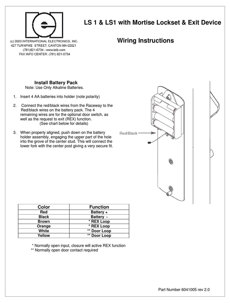
1. C onnect the F lex C irc uit from raceway to C ontrol Module
(note orientation of cable). Make sure cable is fully seated.
2. C onnect the red/grey wires from C ontrol Module to the red/grey
wires from the L ocks et. At this time, plug in the optional request
to exit (R E X)/ Door S witch cable.
(S ee the chart below and F igure 8A.)
3. Hang the Control Module on the center stud on the backplate
allowing the smaller portion of the hole in the C ontrol Module
Bracket to fit down into the groove on the stud. Note: T he fork in
the lower part of the C ontrol Module bracket will fit over the stud
at the Inside Lower Housing screw on the backplate.
C ontrol Module
and B attery P ack
Figure 8
1. C onnect NOR MALLY OP E N free exit (R E X) device
to the B R OWN and OR ANG E wires
2. C onnect NOR MALLY C LOS E D door position s witch
to WHITE and YE LLOW wires
C onnecting R E X and Door P os ition S witch
to J 4 (OP TIONAL )
5A
C onnector Des cription
J1
J2
J4
J5
Battery Connector
Keypad Connector
for F lex C able (26 P in C onnector).
Flex cable connector is keyed to
guarantee proper connection
REX and Door input loops
Motor Cable
Brown
Orange
Green
White
Yellow
Gray
R E X Loop
R E X Loop
not used
Door Loop
Door Loop
not used
1
2
3
4
5
6
P in Wire C olor F unction
1
2
3
R ed
Black
not used
Battery +
Battery -
P in Wire C olor F unction
1
2
R ed
Gray
Motor A
Motor B
Interior B ackplate
F lex C ircuit
1
C ontrol Module
6 C onductor
Wire Harness
J4 R eceptacle (R E X/DOOR connection)
Figure 8A
J2 R eceptacle (F lex C ircuit connection)

6
1. S lide the inside lower housing over the lever tube until it has
passed over the lever catch. Make sure no wires are
pinched by the lower housing.
2. Fasten with two brass #8 screws. Once secure, fasten the
finished #8 screw at the bottom.
3. R emove red strip form battery pack to power the unit before
continuing.
Brass #8 S crews
Finished #8 Inside Lower Housing
Lever C atch
B attery C over
#8 S crews
Inside Lower
Housing
C enter
Grooved S tud
1. Attach the battery cover with two finished #8 screws.
Battery cover has a lip which engages the lower inside
housing, it is important that this lip be seated properly to
insure correct alignment.
1. Insert cylinder retainer into lever until flush with base of lever.
2. P ush lever on door in horizontal position until secure.
R emove red strip
to engage battery pack
Ins talling Interior As s embly
(part 2)
Figure 9 Figure 10
AA
Lower Housing
B
Battery Cover
C
Interior Lever
Interior Lever
C ylinder
R etainer
Electrical
Symptom Probable Cause Correction
1. Beeping after assemby is completed
(4 long beeps) Low Voltage R eplace B atteries
2. S olid green LE D, no motor action C ontrol Module not sending lock/unlock pulse Verify continuity of wire harness and
replace if necessary
3. Yellow LE D flashes and sounder chirps
after install Unit not intialized C onta ct IE I
4. Motor locks but will not unlock
5. Unable to change system default
R E X loop is shorted
(Brown and Orange on P 4 wire harness ) Inspect connection and remove short
V arious C onta ct IE I
Mechanical
Symptom Probable Cause Correction
1. Lever S ticks or is sluggish Hand is too close to front escutcheon Tighten motor spacer ring
2. Handle rests in down position Bushing is not set correctly R emove handle and set bushing in escutcheon
3. C annot s nap on handle A. C has sis not adjus ted correctly
B. Chassis lever locking tab is damaged or missing
A. Adjust to correct setting
B . C ontact IE I
4. C annot tighten the raceway by hand
5. Latch works in only one direction
R ace threads are damaged Use thread chaser to clean threads or contact IE I
The backset is not centered on the latch retractor C enter the backset on the latch retractor
TROUBLESHOOTING
4 of 6
F C C Label
7
6. Does not read proximity cards Unit may not be an LS -2P C heck the FC C Label (see F igure 10). If the label does not refer
to model LS -2P then it is an LS -2 and not an LS -2P .

12A
Tailpiece in
horizontal position
B IC C ore C ylinder
Tailpiece in
vertical position
A C onventional C ylinder
For R ight or Left Handed Operation
Installing The Exterior Levers
1. Tailpiece must be in a vertical position in cylinder. (Fig. 11A)
2. Insert cylinder in lever.
3. P ress cylinder retainer into lever until flush with base of lever
4. Align lever catch to face latch front (see Fig. 5).
5. T urn key in cylinder 45° in either direction.
6. S lide lever on tube until it stops at the lever catch.
7. S lightly wiggle and push until lever engages lever catch
and connector.
R emoval Tool
Conventional Cylinder (Figure 11)
Outs ide L ever
IC Core Model (Figure 12)
Ins talling IC C ore
1. P ush lever on door in horizontal position until secure.
2. Insert control key (marked with a “C ”) into IC core and
turn c lockwis e.
3. Insert tailpiece (S ee chart below.) into core. (Fig. 12)
4. With control key in core, insert core fully into lock.
5. Turn control key 15° to lock cylinder in place.
R emove control key.
IC Lever C atch
Removal of Levers (Interior/E xterior)
1. Insert lever removal tool in slot. (Fig.13)
2. Depress lever catch and pull lever to remove
1. Insert key into cylinder and turn 45°in either direction.
2. Insert lever removal tool in slot. (F ig. 14)
3. Depress lever catch and pull lever to remove.
C onventional Tailpieces included for the Door G ard LS -2 levers
Part No.
LS 1P-TLS
LS 1P-TIL
LS 1P-TS G
FOR
IE I C ylinders
Ilco C ylinders
S chlage C ylinders
I.C . Tailpieces For the Door G ard LS -1
To R emove IC C ore Lever Handle
C orrect Orientation of S pacer
S pacer to convert 7 pin
7 pin IC C ore C ylinder
For
LS 1P -TIC S
LS 1P -TIC 7
Part No.
Outside Lever
Inside Lever
Figure 11
Figure 12
Figure 13 Figure 14
Figure 11A
Figure 12A
AA
B
9
R emoval Tool
8
5 of 6
Note: C ylinders provided by others

©2003 International Electronics,Inc.• 427 Turnpike Street,Canton,MA 02021
(800) 343-9502 • Fax Info center: (781) 821-0734 • www.ieib.com
INSTALLATION INSTRUCTION EXPLODED VIEW
MOTOR CABLE
(FROM LOCKSET ASSEMBLY)
FLEX CIRCUIT THROUGH DOOR
SEE FIGURE 6
MOTOR CABLE
LATCH
STRIKE PLATE
3/4" FLATHEAD WOOD SCREWS FOR INTERIOR MOUNTING PLATE
3/4" FINISHED
BATTERY COVER SCREW
11/2" FINISHED #8 BATTERY COVER SCREW
RETAINER
LEVER CATCH PIN
1" BRASS
THROUGH-BOLTS
CHASSIS ASSEMBLY
RETRACTOR
BATTERY COVER
INTERIOR LOWER HOUSING
INTERIOR LEVER
CONTROL MODULE
RACEWAY NUT
RACEWAY
INTERIOR MOUNTING PLATE
EXTERIOR HOUSING
OUTSIDE SPINDLE
LEVER RELEASE
TOOL
LOCK CYLINDER
RETAINER
STANDARD LOCK
CYLINDER
EXTERIOR LEVER
Qty Description
2 1/2" brass #8 flathead screws
2 1" brass through-bolts for lockset (oval head)
2 1" flathead wood screws for strike plate
4 3/4" flathead wood screws (for latch and interior mounting plate)
2 3/4" finished #8 screws (oval head)
1 1 1/2" finished #8 screw (battery cover top)
Hardware Pack
Battery Pack/
Control Module
Interior
Backplate
Interior and
Exterior Handles
Raceway
Nut
Cyliner
Retainer (2)
Tailpiece
Spacer
Lock
Cylinder
Latch
Raceway
Washer
Lever Release
Tool
Strike Plate
Inside Lower
Housing
Battery
Cover
LS2/LS2P
Exterior
Chassis
Assembly
RACEWAY
SPROCKET
3/4" FINISHED SCREW
1/2" BRASS #8 FLATHEAD SCREWS
3/4" FLATHEAD WOOD SCREWS
1" FLATHEAD WOOD SCREWS
6 of 6
FCC LABEL
IC Core Model
Note: Cylinders provided by others
See Step 8 for details
10
This manual suits for next models
1
Table of contents
Other IEI Technology Door Lock manuals
Popular Door Lock manuals by other brands

IEC
IEC Trimec ES150 instructions

Kaba
Kaba 5 00 Series installation instructions

GEZE
GEZE Hook bolt Lock A installation instructions

Eurospec
Eurospec Push Bar Panic Bolt installation instructions

Assa Abloy
Assa Abloy Corbin Russwin Access 600 CL33600 TCRNE1... installation instructions

Kwikset
Kwikset SmartCode 9270CNT-514S quick start guide

Link
Link SmartLINK M 13 85 Operation and installation manual

Siemens
Siemens Codoor CD3500 Installation & user manual

Salto
Salto XS4 Mini installation guide

Yale
Yale Doorman user manual

Access Control Solutions
Access Control Solutions Eternity 4 Owners manual and software guide

Maco
Maco A-TS Assembly instructions