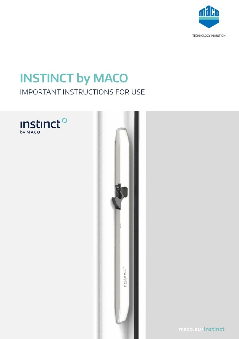
Maco A-TS User manual

www.maco.eu
TECHNOLOGY IN MOTION
PROTECT DOOR LOCKS
A-TS
Automatic Door Lock PVC
ASSEMBLY INSTRUCTIONS
Use only for
certified specialists!

2
WINDOWS · DOORS · SLIDING DOORS
Table of Contents
Item Page
Important Notes 4
Key 5
Use of transportation protection devices 6
Instructions for use 7 - 11
Installation Instructions 12 - 17
Set lock for day release function (assembler) 13
Assembly day release element on the lock (assembler) 14
Assemble MACO day release opener on striker plate (assembler) 15
Operating instructions day release (end customer) 16
Positions 17
Drilling and milling Images 18 - 20
Lock case and multi-function latch with hook lock 18
Latch and shootbolt striker plate 19
Multi-function hook striker plate 20
Positioning of the striker plates 21 - 26
2 Multi-function latch with hook, standard K+730, 1-sash 21
2 Multi-function latch with hook, standard K+730, 2-sash 22
2 Multi-function latch with hook, Low K+605, 1-sash 23
2 Multi-function latch with hook, Low K+605, 2-sash 24
2 Multi-function latch with hook, High K+980, 1-sash 25
2 Multi-function latch with hook, High K+980, 2-sash 26
Lengthening/shortening of the A-TS K+730 27 - 28
Module without additional locking point 27
Module with additional locking point 28

3
WINDOWS · DOORS · SLIDING DOORS
Table of Contents
Item Page
openDoor Access Solutions 29 - 40
Overview 29
A-TS Transponder Plus 30
A-TS Transponder Keypad and Touchkey 31
A-TS Somfy GU Controller 32
Circuit Diagram frame-side 33
Circuit Diagram button impulse 34
Circuit Diagram toggle switch 35
Milling image Transponder Plus 36
Milling image Keypad / Touchkey BT 37
Milling image including connector plate and motor 38
Cabletransitionforopeningangle≤110°,PVC12air 39
Cabletransitionforopeningangle≤180°,PVC12air 40

4
WINDOWS · DOORS · SLIDING DOORS
Important Notes
Target audience
Thisdocumentationisintendedexclusivelyforspecialistcompaniesandcertiedspecialists.
Thework-stepscontainedmayonlybecarriedoutbycertiedspecialists.
Instructions for use
• Unlessotherwiseindicated,measurementsaremadeinmillimetres.
• Assemble all hardware parts professionally as described in these instructions and observe
allsafetyinstructions.
• Alldiagramsareonlysymbolic.
• Withthespacer-blocksetting,observetheglazingtechnicalguidelineNo.3forthe"Blocking
ofGlazingUnits".
• Observethe"GuidelinesandInstructionsforProductandLiability(GIPL)".
• Informtheenduseraboutthecontentsofthe"GuidelinesandInstructionsforEndUsers
(GIEU)".
• Printingerrors,mistakesandchangesarereserved.
Material information
• The hardware parts described in this guide are made of stainless steel or galvanised
passivatedsteelandsealedinaccordancewithDINEN12329.Theymustnotbeusedin
environmentswithaggressive,corrosiveaircontent.
• Donotuseacid-curingsealants,asthesecanleadtocorrosionofthehardwareparts.
• Thedoorlockelementsmayonlybesurface-treatedbeforethehardwareisinstalled.
Anysubsequentsurfacetreatmentmayrestrictthefunctionalityofthehardware.Inthiscase,
nowarrantyclaimscanbemadeagainstthehardwaremanufacturer.

MF
EV
FFH
K+
K-
5
WINDOWS · DOORS · SLIDING DOORS
Backset DM
DistanceE
Handle height GM
ProleFrontEdge
Multi-function latch
Endpiece
Important note
Key
Sash rebate height
Case dimension top
Case dimension bottom

A
A
6
WINDOWS · DOORS · SLIDING DOORS
Simple transport protection devices, wedges or blocks ensure a safe transport of the entire
doorelement.Removeonlyafterinstallation.
Use of transportation protection devices
ATransport protection device position

7
WINDOWS · DOORS · SLIDING DOORS
Instructions for use
Removeswarffromthemilledspace!
Drillallholesbeforeinstallationofthelock! Do not force the handle pin through the lock
nut!
Neveropenthelockcase!

8
WINDOWS · DOORS · SLIDING DOORS
Instructions for use
Donotturnthekeyusingforce! Do not simultaneously press the key and
handle!
Only close the lock with the corresponding
operatingkey!
Do not use force during the cylinder
assembly!

9
WINDOWS · DOORS · SLIDING DOORS
Instructions for use
Only apply load to the handle in the normal
direction!Applyamaximumforceof15kgin
thedirectionofactuation(onthehandle)!
As soon as traces of forced use are visible,
thelockmustbereplaced!
Two-sash doors must not be forced over the
inactiveleaf!
Do not close the lock latch when the door is
open!

10
WINDOWS · DOORS · SLIDING DOORS
Instructions for use
Donotcarrythedoorleafwiththehandle!
Do not paint or varnish over the padlock bolt
orlatch!

11
WINDOWS · DOORS · SLIDING DOORS
Instructions for use
The door lock (lock case) is delivered with an intensive lubrication of high-performance
greasesandmustNOTbere-lubricated!
LubricatetheMF-HOlockingelement1xannually!
* Spray grease (455341), ** Rust remover
Do not use any lubricating oils, rust remover, silicone sprays etc!
Lubricate only with grease or technical petroleum jelly! Lubricate the
latch and locking bolt 1x annually!

2
3
1
4
ab
c
d
a
e
2
3
3
1
4
2
3
1
4
ab
c
d
a
e
2
3
3
1
4
2
3
1
4
ab
c
d
a
e
2
3
3
1
4
12
WINDOWS · DOORS · SLIDING DOORS
a= Faceplate
c= Latch
d= Latch insert
e= insert leg of latch insert
1Loosen the screw
completely and push
forward with the
screwdriver!
2 Removethelatch!
3Turn the latch over and
place it on the faceplate
(a) so that you can press
the insert leg (e) of the
latch insert (d) under the
faceplaterecess(b).
Only then press the
latchincompletely!
4 Screwin(torquemin.
1.5Nmtomax.2Nm)!
Crank latch Multi-function latch
Perform functional check!
Installation Instructions

2
3
1
13
WINDOWS · DOORS · SLIDING DOORS
1Lock
2Removethedayreleasescrew(2.5mm
hex socket)
3Unlock
If the day release function is set, the main latch is not actuated during
motorised operation (door does not automatically jump open)!
Set day release function Manufacture delivery state
1Lock
2Insertdayreleasescrew(2.5mmhex
socket)
3Unlock
Installation Instructions
Set lock for day release function (assembler)

1
2
3
4
14
WINDOWS · DOORS · SLIDING DOORS
1 Removethefaceplatecover.
2Position the day release element on the back of the faceplate (directly on the latch above
the lock case)
3 andpushontothelockcase.
4Screw on the day release element with the attached TX20 M4x10 screw on the front of the
faceplate!
Installation Instructions
Day release element assembly on the lock (assembler)

12
3
15
WINDOWS · DOORS · SLIDING DOORS
1 Removethelatchinsert.
2 AssembletheMACOdayreleaseopener.
3 Activatethemechanicalunlockingonthedayreleaseopenerusingthelever*.
* Mechanical unlocking can remain activated as the day release function is controlled by the day release slider on the
lock (see “Day Release Function" user manual, Page 16).
Installation Instructions
MACO day release opener assembly on the striker plate (assembler)

1
2
1
2
1
2
1
2
1
2
1
2
1
2
1
2
16
WINDOWS · DOORS · SLIDING DOORS
Activate day release function Deactivate day release feature
Installation Instructions
Day release function user manual (end customer)
1Press the handle so that the locking
element and the multi-function latch are
pulled in
2Slide the day release slider upwards,
releasethehandle!
1Press the handle so that the locking
element and the multi-function latch are
pulledin!
2 Slidethedayreleasesliderdownwards!
The A-TS basic function, automatic locking, is
restored!

17
WINDOWS · DOORS · SLIDING DOORS
Position of latch and shootbolt striker
plate
Position of striker plate, multi-function
latch with hook
Pressure adjustment:
+/- 2 mm with latch and shootbolt striker plate
+/-1.5mmwithMF-HOstrikerplate
Positioning of notch faceplate = notch strike plate
A rebate clearance of 10 - 14 mm must be kept in the installed state!
Installation Instructions
Positions

15,5
38
71
45DM
≤2
12
46
150
4
15,5
42,5 ≤2
12
∅
4
17,5
DM
∅
4
385
30
6,5
85
1,5
21,5
6,5
E
GM
9,5
1
1
16,2
12,2
9,3 2,2
+0,2
- 0,1
+0,2
- 0,2
+0,2
- 0,1
+0,2
- 0,1
18
WINDOWS · DOORS · SLIDING DOORS
1Notch faceplate
Proposed
cable position for access solution
Lock case
Drilling and milling images
Lock case and multi-function latch with hook lock

24*
20
3
26*
20
250
32
82
90
16 33*
3030
102
110
23
15
58
40* 40*
R3
R3*
19
WINDOWS · DOORS · SLIDING DOORS
Drilling and milling images
Latch and shootbolt striker plate
*Milling E-opener

R3
X
18 3
65
22
45
180
32
23
65
45
20
WINDOWS · DOORS · SLIDING DOORS
Drilling and milling images
Multi-function hook striker plate
X
2 MF-HO
+726
0
-764
Other manuals for A-TS
2
Table of contents
Other Maco Door Lock manuals

Maco
Maco PROTECT Manual

Maco
Maco PROTECT STABLE DOOR LOCK User manual

Maco
Maco INSTINCT User manual
Maco
Maco INSTINCT User manual
Maco
Maco SMART DEADBOLT User manual

Maco
Maco ML196 User manual

Maco
Maco RAIL-SYSTEMS HS Profine PremiDoor 88 PVC Quick start guide
Maco
Maco A-TS User manual
Maco
Maco A-TS Series User manual