2 | Product Description
2.1 Type code
This operating instructions manual is valid for the following types:
M 13 85 Guard-/ lock plate for tube frame*
M 13 86 Guard-/ lock plate for wood*
M 13 25 Lock plate / mounting box for tube frame*
M 13 26 Lock plate / mounting box for wood*
* hereinafter referred to in the operating instructions manual as
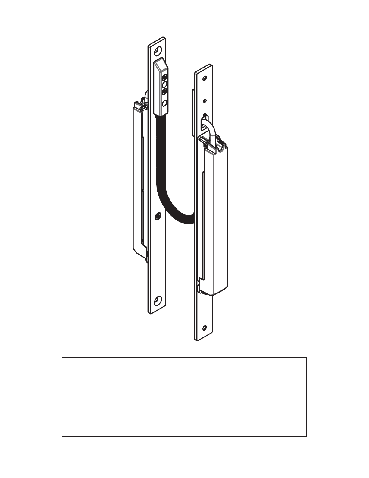
„SmartLINK“
2.2 Terms and conditions and use
The SmartLINK is intended for installation in all standard timber, PVC
and aluminium profile doors. It is used to secure the transmission of
signals and voltages of the connected components.
The SmartLINK enables domestic and commercial doors to be simply
and economically connected to power sources and signal sources,
such as fingerprint, engine locks, etc. Due to the ease of installati-
on and its construction, the domestic and commercial doors can be
completely manufactured in the workshop, tested as an assembly and
accepted in the object immediately after installation.
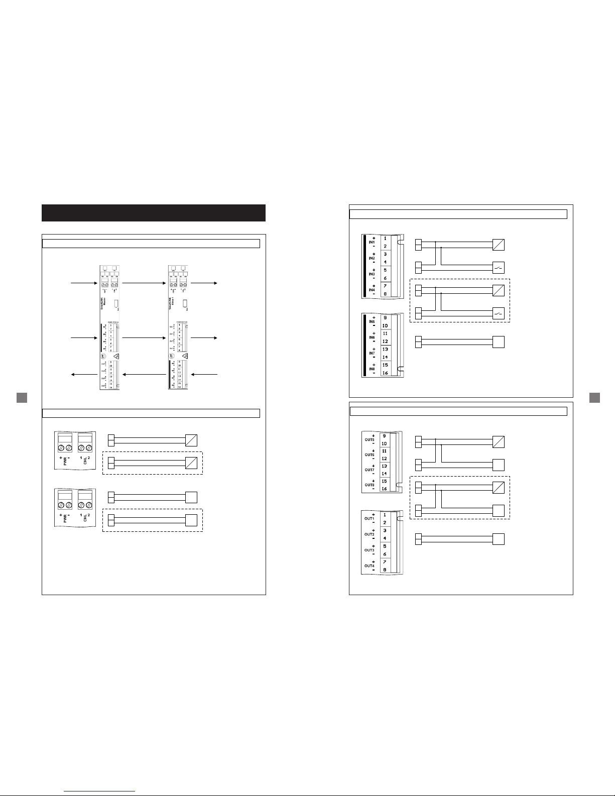
2.3 Technical data
• Power supply 1 (PWR): 12 – 24 V DC, 3 A DC,
2 pole screw plug-in terminal, black, RM 3.5 mm,
max. core cross-section: 1.0 mm²
• Power supply 2 (CHL): 0 – 48 V DC,
5 A DC (2 sec. ED, see Fig. 2.3), 2 pole screw plug-in terminal,
black, RM 3.5 mm, max. core cross-section: 1.0 mm²
• Inputs (IN 1 – IN 4): galvanically isolated,
max. 48 V DC / 5 mA DC, 2 pole screw plug-in terminal, black,
RM 3.5 mm, max. core cross-section: 1.0 mm²
• Outputs (OUT 1 – OUT 4): galvanically isolated, max. 48 V DC /
500 mA DC, 8 pole screw plug-in terminal, black,
RM 3.5 mm, max. core cross-section: 1.0 mm²
• Operating temperature range: -20°C to +70°C
• Line connection (KÜ): LiF9Y11Y 6 x 0.34 mm², halogen-free
• Housing: Plastic (ABS), protection type IP 42
• Weight: 600 g.
3 4
8,5
322
280
300
20
4,5
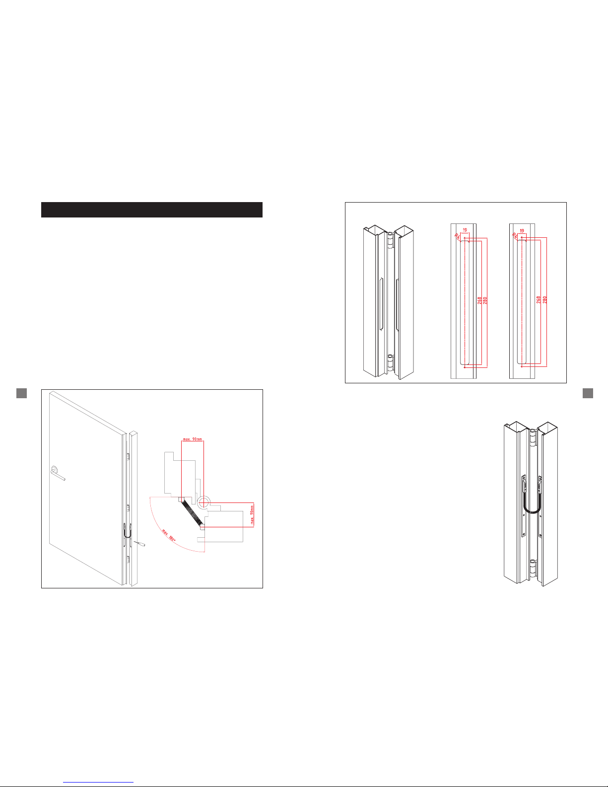
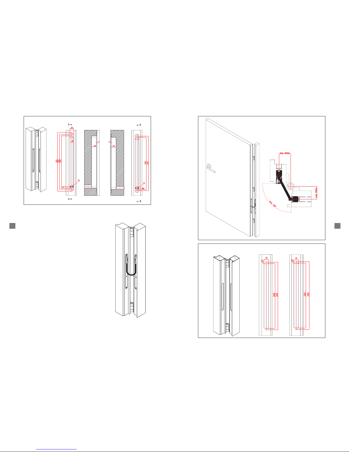
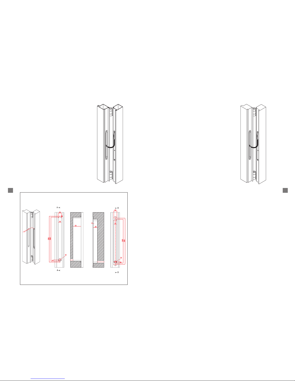
Dimensions
Figure 2.3
Current / Time
Current [A]
Duration [s]
CHL