IEM Umwelt 3 Quick guide

IEM
INDUSTRIAL EQUIPMENT AND MACHINERY GMBH
Tel. +49(0)6131/914694 • Fax +49(0)6131/963109
Reverse Osmosis Unit
UMWELT 3
Installation-and Instruction Manual
This Installation-and Instruction Manual shows you all the steps for the Installation of the Reverse
Osmosis Water Filtration Unit, which can be easily done by you. If you don´t want to install it
yourself, please contact am adequate plumber on location.
IEM
INDUSTRIAL EQUIPMENT AND MACHINERY GMBH
Tel. +49(0)6131/914694 • Fax +49(0)6131/963109
Preparations before the Installation
1. The Unit can operate horizontal as well as in vertical Position. We recommend the vertical Installation
because of the easier Way to change the Filters. Please be sure to have enough Space for the Replacement
of the Filters. At the same Time the Unit should be installed near the Water Supply to avoid Pressure Drops
through short Pipes.
2. The Tank should be positioned, where it doesn´t displace. It doesn´t need to be fixed and can be displaced
later, if necessary.
3. The Tap should be positioned, so that the Water can drain into a Sink. When Mounting, please be sure, that
there is enough Space for the Faucet.
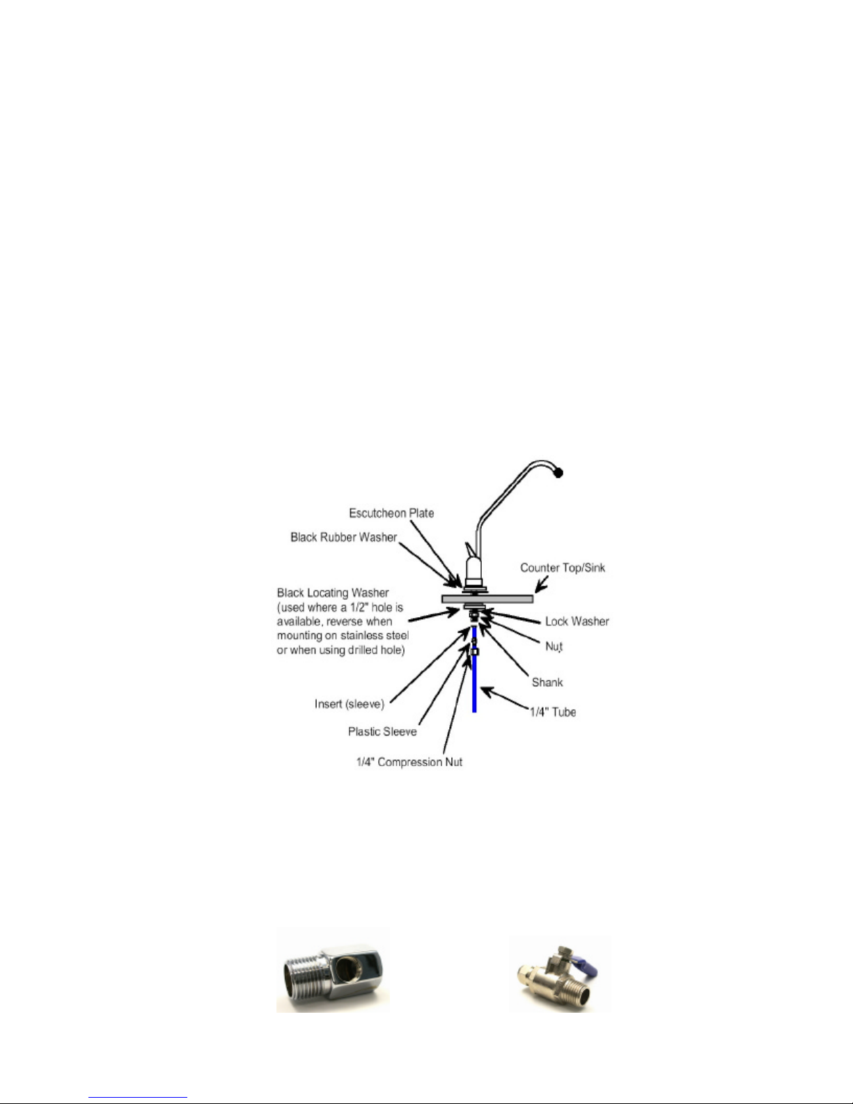
Mounting of the Faucet
1. For the Faucet you need a Boring of Ø12mm. For Stainless Steel Sinks we recommend a Tapered Drill (No.
11802/3-14mm).
2. For wooden Counter Tops up to 25mm Thickness, you can use a Wood-or Metal Drill.
3. For wooden Counter Tops up to 40 mm Thickness, you need to countersink min. 15mm from the Bottom,
using a Fortner-Drill (Ø40mm-No. 79510/40mm). Drill with a small Borer from the Bottom to the Top and
afterwards rebore the Hole from the Top, using a 12mm Drill.
4. To tighten the Armature you need a 14mm Für das Festziehen der Armatur (Einbauhahn) benötigen Sie
einen 14mm Socket Wrench (Nr. 62010/14x15). Please position the Plates and Seals as shown below and
tighten the Nut.
Installation of the des Water Connection
*** Please be sure, that the Water is shut off, before working on the Water Pipe Net. ***
For the Water Connection, we enclosed two Parts:
§Feed Water Connector (A130) with ½” Inner-and ½” Outer Thread, with ¼” Inner Thread for the
Connection of the Ball Valve (A200)
§Ball Valve (A200) with 1/4“ Inner–and Outer Thread
Feed Water Connector (A130) Ball Valve (A200)

IEM
INDUSTRIAL EQUIPMENT AND MACHINERY GMBH
Tel. +49(0)6131/914694 • Fax +49(0)6131/963109
Mounting of the both Parts to the Water Pipe Net:
Mounting of the Ball Valve to the Feed Water: wrap 3 to 4 Layers of Teflon Band around the Outer Thread of
the Ball Valve and screw it inside the Feed Water Connector.
Remove the Cold Water Connector below the Sink from the ½”-Connection (mostly Angle Valve).
Mount the Thread Nipple and reconnect the ½”-Connector (Don´t forget to seal the Threads with Teflon
Band!).
Drain Clamp
Connection to the Drain Pipe:
1. The Drain Clamp has to be mounted to the upright Drain Pipe of the Sink, in front of the Sifon.
2. Drill a 6mm Hole into the Drain Pipe.
3. Bond the Sealing on the Adapter.
4. Fit the Adapter to the Drain Pipe (Holes to be centered by Drill).
5. Do not tighten the screws too hard.
Connecting of the Tubes
1. Connect the white Tube to the Feed Water Connector (max. Salinity of Feed Water: 600 ppm).
2. Connect the blue Tube with the Product Water Faucet.
3. Connect the black Tube to the Drain Clamp.
Initation of the RO Unit
1. Connect the Unit to the Power Socket and switch on the Master Switch at the back of the Unit.
2. Open the Feed Water, in order to check the Unit for leaking Connections.
3. After a few Minutes the Water will flow out of the Product Water Faucet.
(can last up to 5 Minutes, according to Water Pressure).
4. Let the Water flow for approx. 30 Minutes, to rinse the Filters sufficiently.
5. After that close the Product Water Faucet. Now the Storage Tank gets filled.
6. When the Tank is full, please drain it completely.
*** Please do not use the Water of the first Flushing of the Storage Tank!***
*** Now the Unit is completely flushed and ready for Use.***
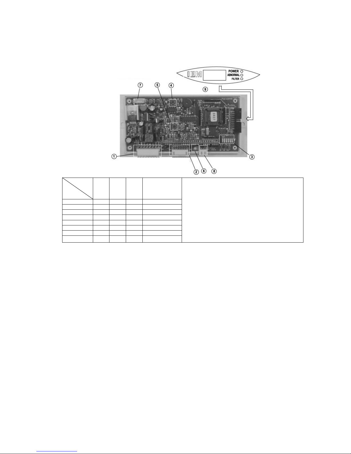
Controller
The Controller is mounted on the Front Side of the Housing below the Covering.
Possible Errors Causes
Leaking The Unit is leaky.
Low Pressure The Feed Pressure is below 1 bar, increase the
Pressure.
Conductivity too high The Unit is defect or the Membrane is deficient.
LED „Abnormal“ blinks The Unit is defect.
LED „Filter“ blinks The Filters need to be changed.
Installation
of the Feed Water Connector
IEM
INDUSTRIAL EQUIPMENT AND MACHINERY GMBH
Tel. +49(0)6131/914694 • Fax +49(0)6131/963109
1P 2P 3P Time of change filter
10001000 Min.
21002000 Min.
30103000 Min.
41105000 Min.
500110000 Min.
610115000 Min.
7 (Umwelt 3) 01120000 Min.
8 (EisCafe) 11112000 Min.
[1] 1P /2P /3P :Set changing filter (refer to left table)
[2] 4P: timing filter/count(flow meter)switch (OFF=>timing, ON)
=>counting (flow meter)
[3] 5P: ON=>Reach time of changing filter, it will display and
stop output.
OFF=>Reach time of changing filter, it will not display and
continue output.
[4] 6P: Setting by supplier OFF (Don’t touch!)
0=>OFF
1=>ON
(1) Power / PUMP/ plug of auto flushing
(2) Low pressure/ High pressure/ Leaking detector/ plug of water detector
(3) Mode setting switch (total 6 option):
(4)The switch of re-timing for changing filter: Set counting numeral “zero” for changing filter. (When operate, please press the switch
continuously, and it will complete when the alarm stop.
(5)Reset switch: Restart the circuit board system.
(6)Adjust water detector sensitivity: Rotate anticlockwise (increase sensitivity), rotate clockwise (decrease sensitivity).
(7) Buzzer: It will alarm when running abnormal.
(8) Plug of flow meter: It can calculate and display the life of filter by way of flow meter.
(9) Plug of LCD display board.
Security Advices
The RO Unit is constructed for a Water Pipe Pressure of 3 –5 bar. In case of a lower Pressure, the Quantity
and Quality of the Product Water will degrade. In Order to counter this, you should plump for an RO Unit with an
included Booster Pump.
At a higher Pressure, the Membrane can be damaged. In this case you should install an additional Pressure
Reducer.
Do not keep the Unit out of Action for a longer Time, since otherwise there is the risk of Bacterial Contamination.
Concerniong the Choice of the Location, please keep the following in mind:
Position the Unit, where it doesn´t displace and can be maintained.
The Unit should be positioned near the WaterSupply, to avoid Pressure Drops through short Pipes.
The Location of the Unit should necessarily have a Bottom Outlet, since possible Leakages can cause Water
Damages. Because of this please obviate an Installation in Conjunction with Furniture.
Please check the Unit regularly for bacteriological and microbiological Contaminations.
If you don´t use the Unit for any Length of Time, please shut down the Current Entry and close the Feed Water
Supply. In this case you should disinfect the Unit before Reconnection.
Besides Rodents (Mice,...) can erode the Tubes.
Table of contents
Popular Water Filtration System manuals by other brands


BWT
BWT Vida 2.6 L instruction manual

Giebel
Giebel DV 300-PA manual

Luminor
Luminor LB4-031/2 owner's manual

WaterLogic
WaterLogic F-FWEG1-M-A-NT Series user manual

Dupla MARIN
Dupla MARIN Ocean Sump OS 200 Operating instruction

Water Right
Water Right Impression Series Installation instructions & owner's manual